I planned to build more 144MHz & 432MHz DK7ZB yagis for contesting to use in arrays so I wanted to ensure I could make them accurately and repeatedly and also without taking forever doing it! Thus I needed to come up with an efficient cutting jig to make accurately cutting yagi elements to size fast and reliable.
I would use some threaded bar to adjust and set the length and steel angle for the supporting the aluminium tube and cutting the length. First I calculated the range of length between the longest reflector and the shortest director then a quick knock up in Solidworks gave me the length of stud required and ideal places to weld the angle to do the cutting. The studding is M12 because a nut for M12 will take a 10mm ali tube with a little clearance. The long M12 barrel nut (Screwfix, few pence) is locktighted in place. From the left the angle brackets have the following holes: 12.5, M12 tapped, 10.5, 10.5, 10.5:
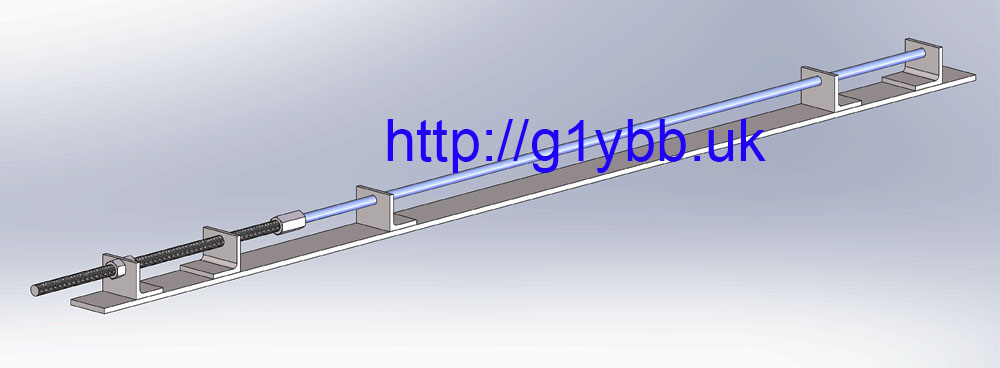
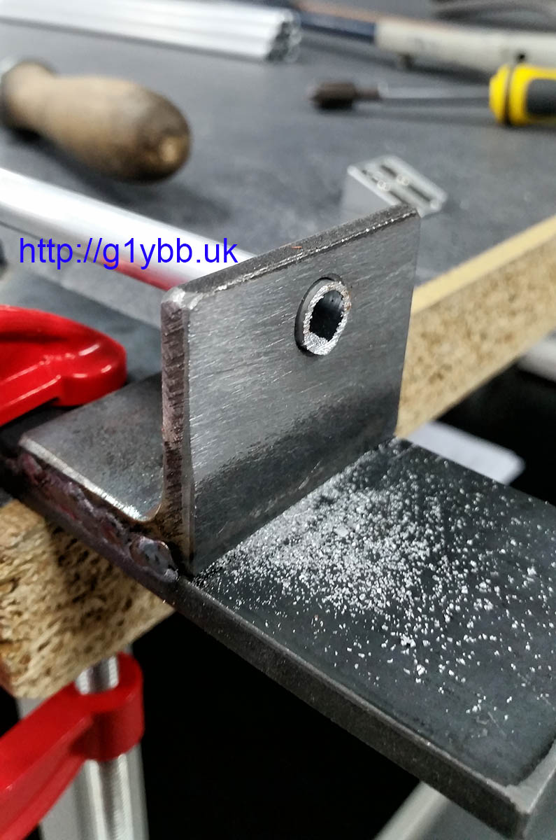
Some cutting, drilling and tapping later and I have this (the observant will note it’s not exactly the same as the intended design-more on that accidental stroke of luck later!):
![]()
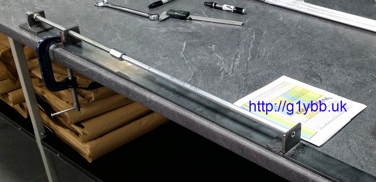
Usage is very straightforward. First I G-clamp it to the bench then I used one piece of spare element tube as the setting piece, doing all elements in sequence, longest to shortest. So I set the jig and adjust, cutting and filing the setting piece until spot on then do all elements that length then onto the next element size using the same setting piece. Simple, but more importantly, very accurate and repeatable. I did try calculating the distance a fraction of a turn would give based on the thread pitch but with a simple tapped hole the thread backlash made it too unpredictable so found it easier to measure the amount the cutting piece protruded when setting for the next size down with the small vernier in the photos above and start from that point and fine tune on the thread and lock nuts.
To actually cut the elements (after using the jig to prepare one end of all elements to ensure it was nice and square and deburred) I just slide it through the 10.5 clearance holes into the long nut and hold it pressed against the long nut with one hand. With the hacksaw tilted slightly to start a cut just away from the steel angle to prevent sawing the face of the steel angle I start cutting then as soon as the cut is started square up the hacksaw. Cutting takes a few seconds:
Then it takes a few seconds more to file the element down flush to the steel angle. Over MANY elements the steel angle will gradually file down in thickness but such a large area and so much harder than the aluminium it will not affect the length between a batch (I checked):
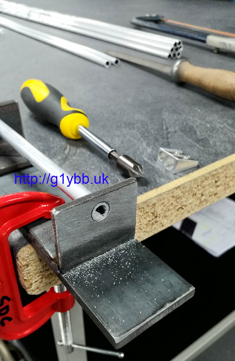
Next to just finish off the end. In the picture above you will notice the countersink bit in the screwdriver handle and a pencil sharpener. Both employed very quickly to deburr inside and outside edges:

The only thing left to do is check the length! I am lucky that my place of work happens to have a very large digital vernier. These will do, close enough for G1YBB…
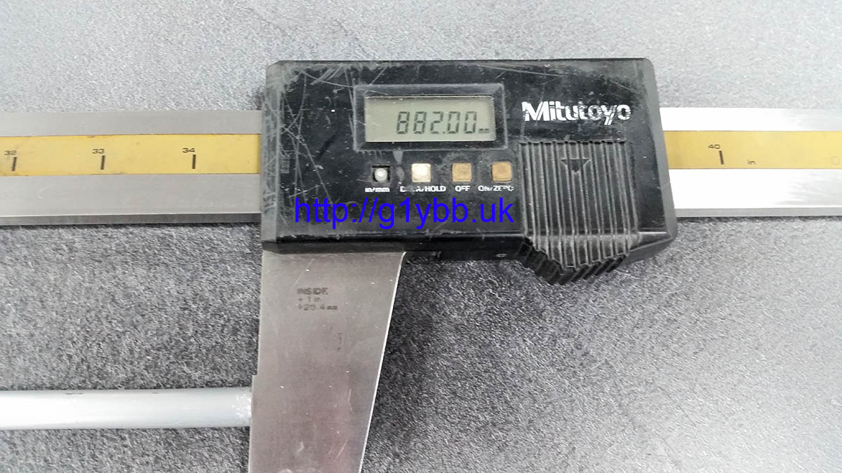
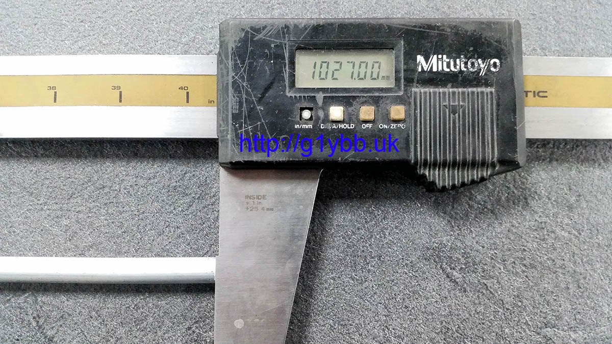
Obviously most people won’t have such a measuring tool but it shows the jig can enable accurate results, more accurate than we can normally measure. I belive working as accurately as possible to follow the simulated design will enable the best possible results to be achieved. I have had fantastic results with my first 9 element DK7ZB working to that ethos.
About that lucky error in placement of the angles with the holes…
One thing I forgot to allow for when designing the jig was the driven dipole halves! But by a stroke of good luck (MOST unusual for me) fitting the middle guide hole angle in the reversed place turned out it was perfectly positioned for the dipole half:
I’ll be able make the 432MHz element cutting jig to cater for dipole halves and full elements easily because the threaded bar covers enough length with the 70cms elements being so small.