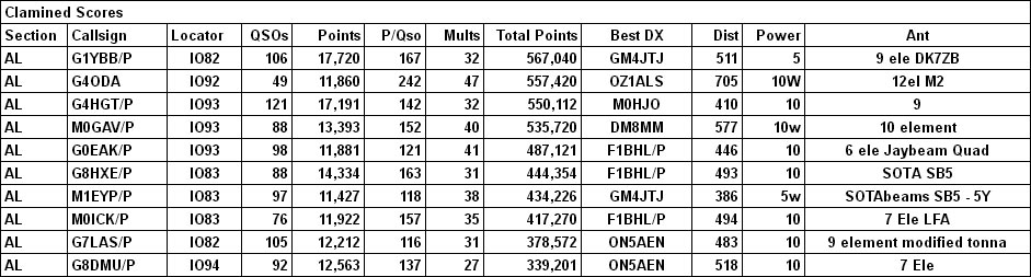
I was scrolling down my Facebook feed and spotted a post in I think one of the SOTA Facebook groups mentioning a BX-184 CQ Parrot. It looked interesting at first, then awesome! Within 20 minutes I had it ordered.
This is a modification to the standard MH-31 microphone that comes with the FT-817, FT-857D and FT-879D etc. It will record and playback a message, perfect for calling CQ Contest or CQ SOTA etc, but without the requirement to carry and connect up another gadget as it fits completely inside the microphone body. It was designed by Oliver DH8BQA and he describes it on his website here http://www.dh8bqa.de/bx-184/.
It is available for sale on the German Funk Amateur site here Funk Amateur BX-184. However they also do another kit that includes an MH-31 microphone body if you don’t want to disturb your original mic and that is the option that I took Funk Amateur BX-184M. The website is all in German so if like me you don’t speak German Google Translate will help a lot! There is also now a USA vendor here http://www.box73.com/product/2
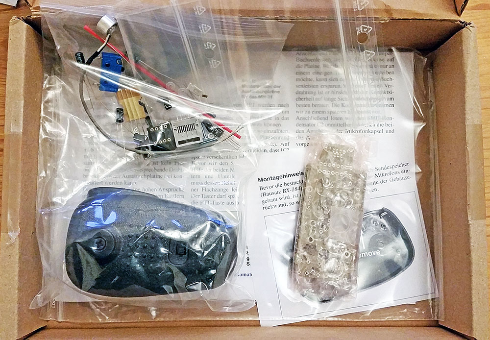
It came pretty quickly and this is what you get in the box:

A complete kit with all you need. The PCB is part SMT (surface mount technology) and part through hole components. You just need to fit the through hole components.
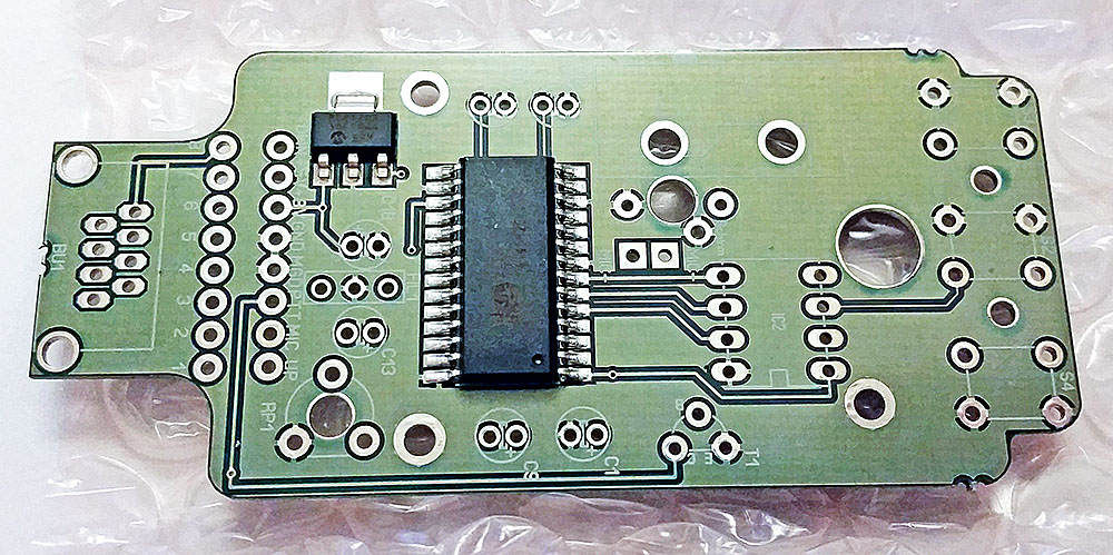
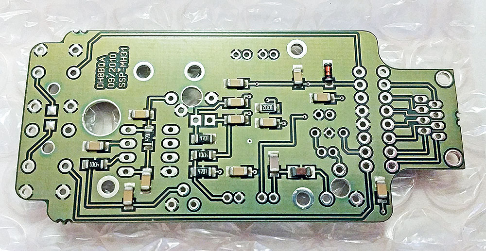
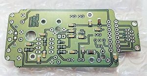
The double sided PTH PCB is very nicely built.
Top:
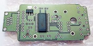
Bottom:
Before it arrived I did some research and found some mods made by DG2IAQ on eHam which sounded worthwhile:
Mod 1:
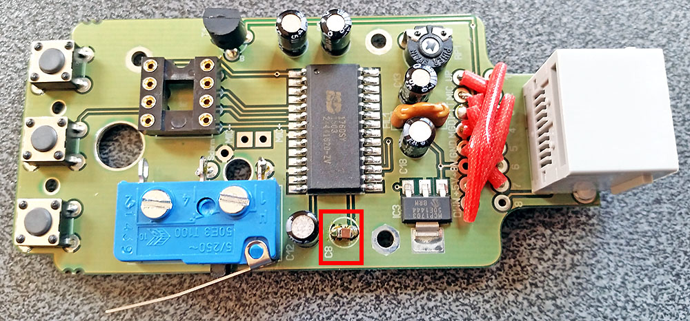
“I do always replace C8 (4,7µF) by a nonpolarised SMD 1,0µF to fasten up the AGC. With this Change the internal AGC works more as a mic compressor than as a (slightly delayed) mic Level limiter.”
Mod 2:
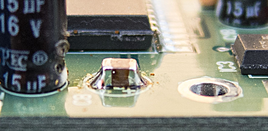
“And for the first time I changed R4 (82k) into 56k to bring the sample rate from 8kHz up to 12kHz (by a shortened play time of 40s instead of 60s, but that’s still more than enough for my needs). This change gives even more punch for the replayed calls as the sound is a little more high-pitched afterwards. You simply can solder a 100k SMD in parallel to R4 instead of completely replacing it.”
I emailed Oliver DH8BQA for his thoughts on these mods and he confirmed they should be worthwhile.
So I decided an 0805 ceramic chip 1µF capacitor would fit best across the pads for the 4.7µF electrolytic it was replacing:
I should have fitted this first as the 15µF cap next to it made it awkward to get a good solder joint on the GND side of the capacitor due to the ground plane wicking the heat away. Got there in the end though:

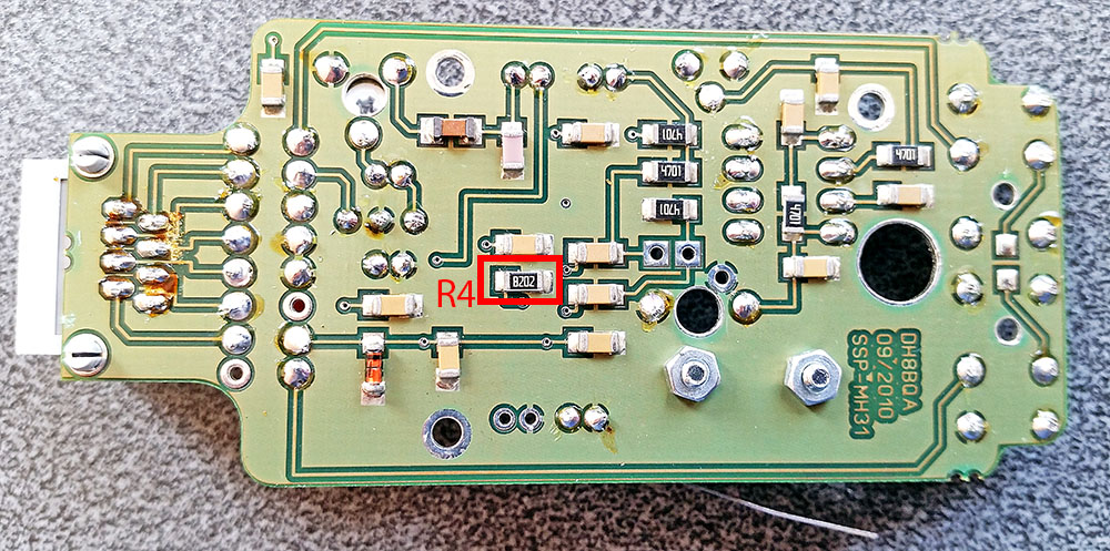
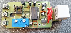
R4 is an 82K 1206 sized resistor located on the rear of the PCB (this is easy to locate as the kit comes with build instructions in German with a good circuit and layout supplied. English instructions can be downloaded here, page 5 onwards
English Build Guide):
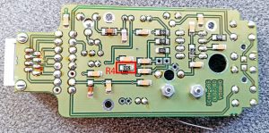
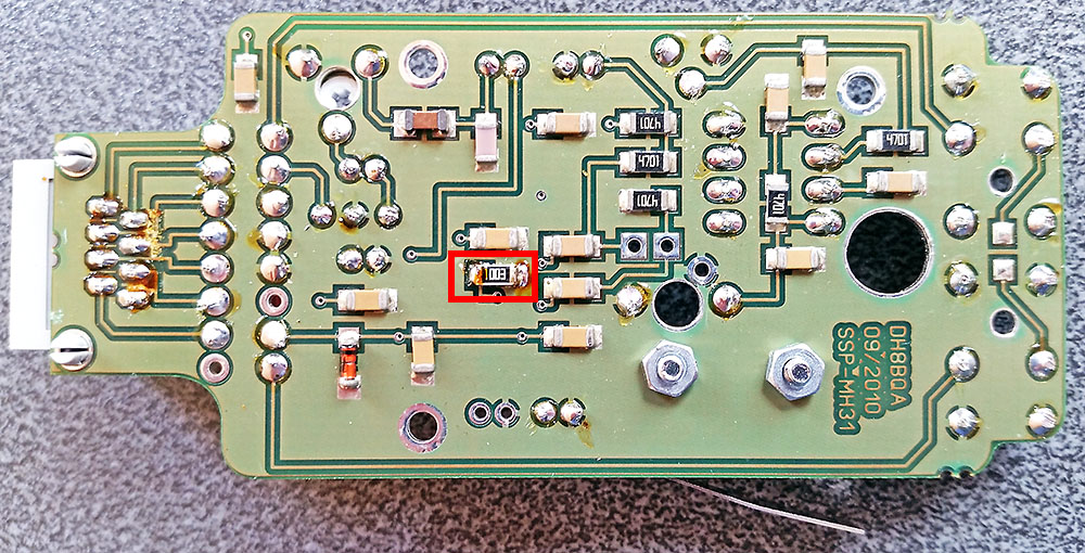
And with a 100K 1206 fitted in parallel (on top of the fitted resistor) as suggested above:
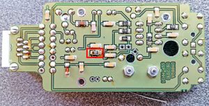
With all parts now fitted (including a 1206 capacitor fitted across the supplied electret insert terminals) all that is left to do is mount the electret insert into the microphone body and solder that to the PCB.
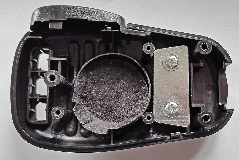
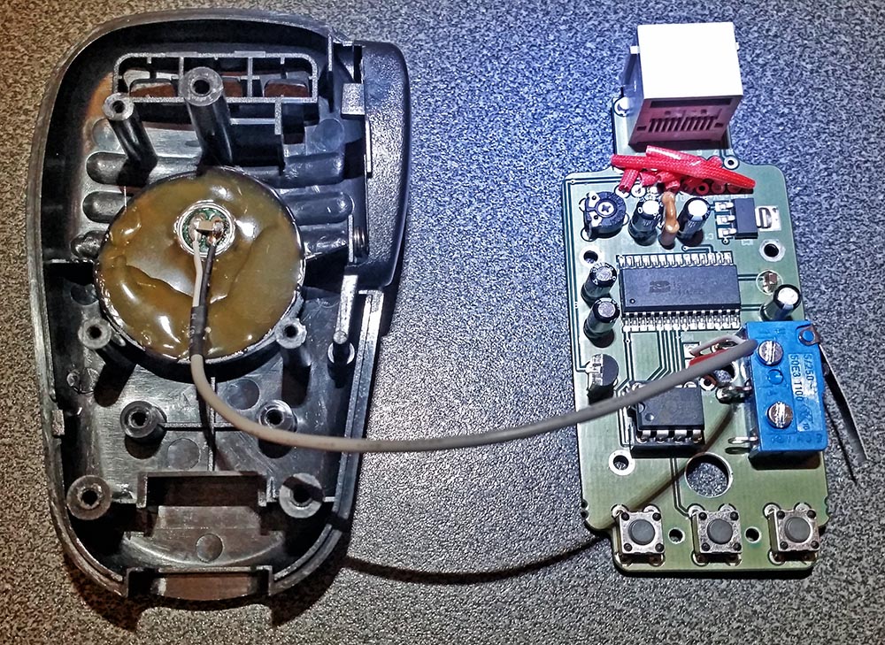
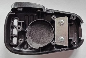
Opening up the supplied microphone and removing the PCB revealed these 2 slabs of steel in the body. The only function of these I could see was to add weight to make it feel more substantial. So I got rid of those. No point in carrying dead weight:
Next I hot melt glued the electret insert into the mic and filled up the void as the instructions said. Actually I filled more than the picture in the build instructions showed by mistake. Then solder the screened cable to the PCB and fit the IC and it’s ready to be assembled:

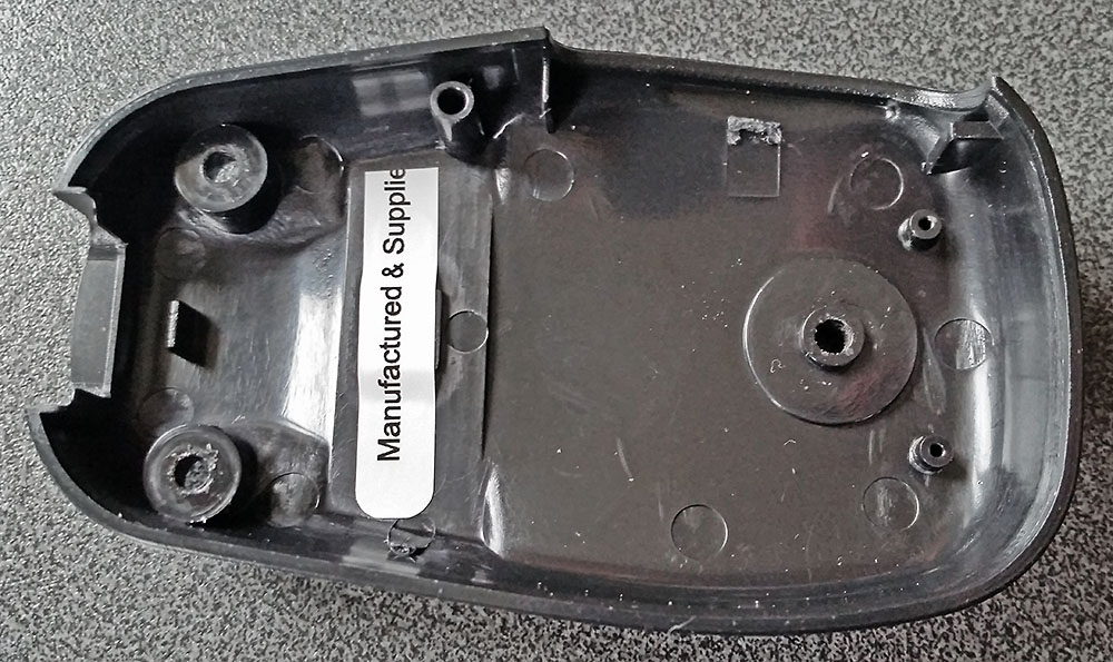
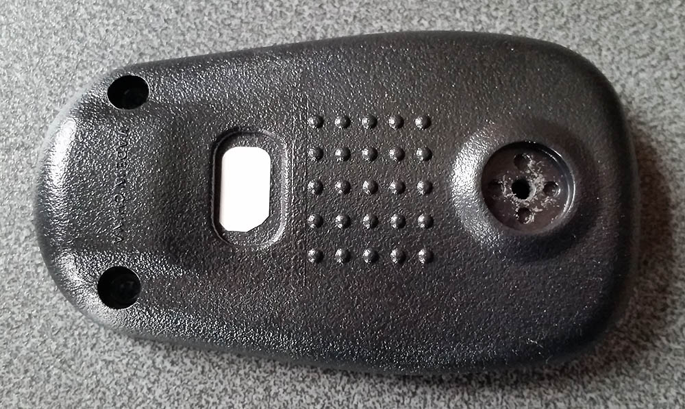
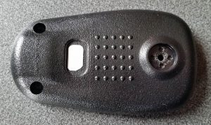
As the replacement PCB does not have the two position slide switch, there is the unused hole in the back of the mic. For this I just used some good quality sticky label material I have to hand.
One piece inside:
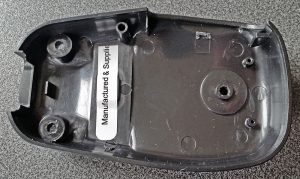
And one on the outside.(not pretty but functional):
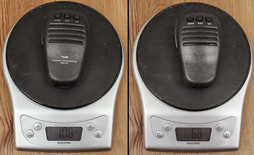
Once assembled I compared the standard supplied Yaesu MH-31 mic for weight against the BX-184 CQ parrot. A 40% saving in weight, I’ll take that:

I soon connected it up to the radio ready to go but there was no outgoing audio! What!? With several projects on the go I could do without time spent fault finding. What if I have cooked the electret soldering the capacitor on now it’s well and truly hot glued into place. Hmmm. Hold on, what was that pot trimmer for? I remembered when building it I couldn’t see any mention of it. A check of the circuit confirmed the obvious answer. It’s on the mic output to the radio. A quick check with the meter confirmed it was currently set to ground the mic line going to the radio. A quick tweak and we are back in business.
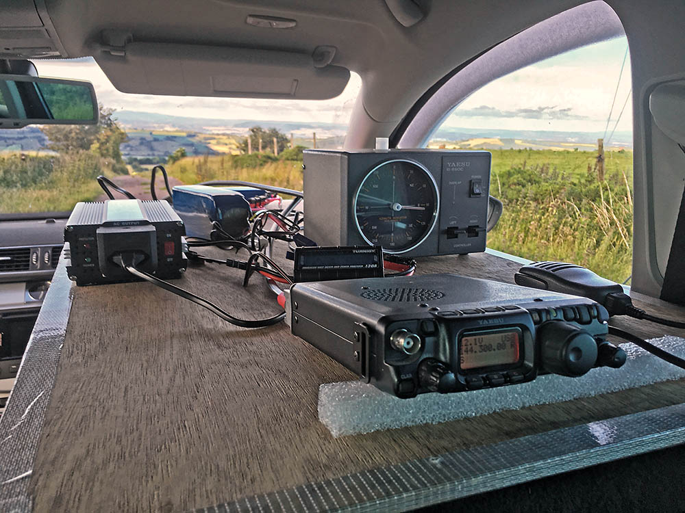
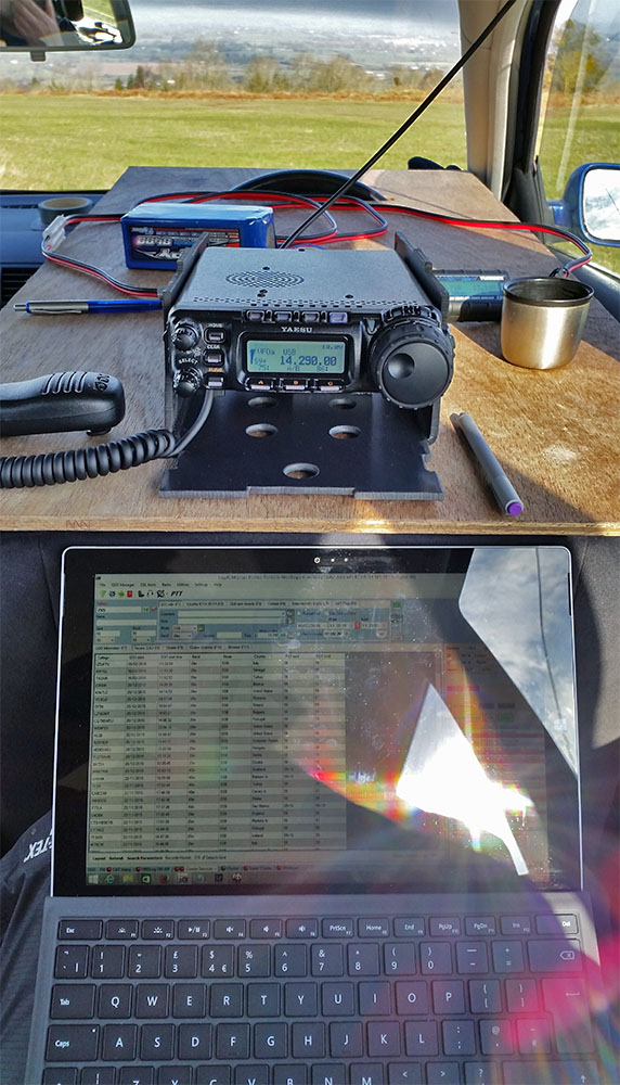
In fact the worst part was setting up to monitor myself. Eventually I had a reasonable system, FT-857D on 5Watts into a dummy load near the FT-897D with a 4mm banana plus as an antenna feeding into the sound card on the PC, with Audacity dealing with the recording. The recordings are not broadcast quality but are good enough for a comparison.
Can’t wait to try this out in a contest or SOTA activation. All in a great little kit well thought out and went together very well. The only small point is no actual mention of the trimmer function or setting which would be good as a reminder if nothing else. I know this kit is aimed at radio amateurs who should be able to look at the circuit and deduce why the pot is there so this is a very minor point in a great kit.
Edit:
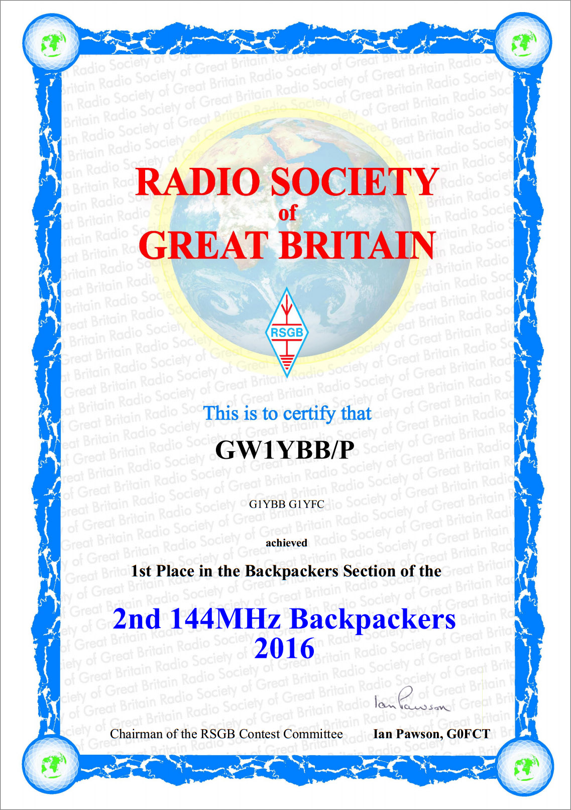
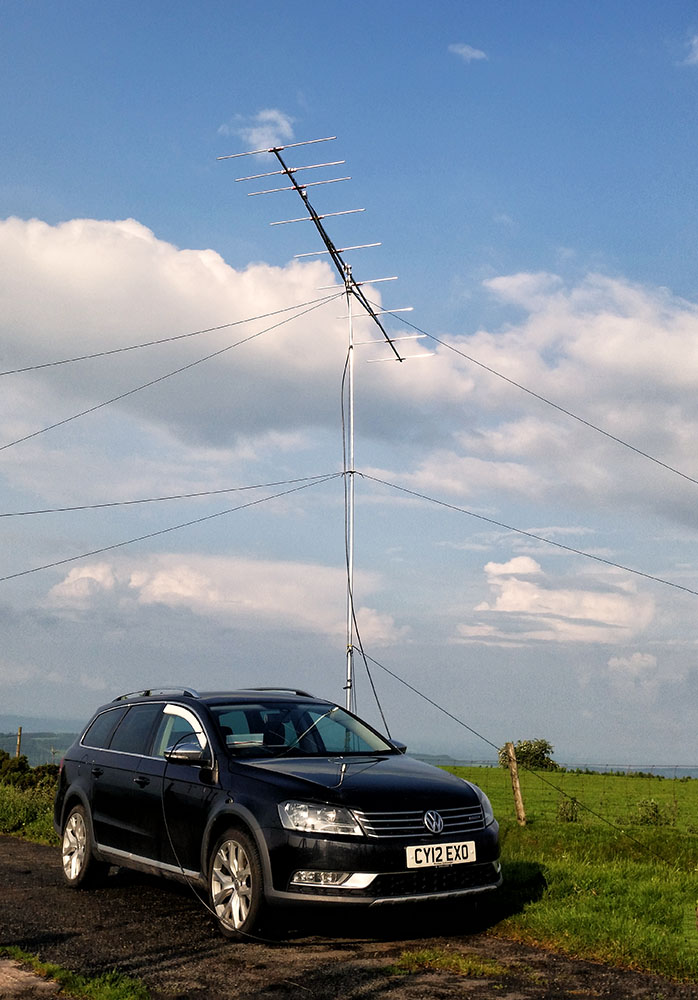
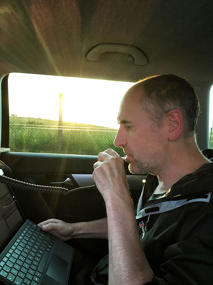
I have since used this ‘in anger’ in 144MHz contests. The first contest I got some complaints about over driving and being wide (complainant was also wide to me for that matter!!). But I turned SSB mic gain down in the FT-817 and back at home I did turn down the audio output level on the microphone itself and did some tests between it and the standard MH-31. Subsequent contests have resulted in zero complaints but some good audio reports.
Last updated 3rd July, 2023