As an avid antenna constructor myself this is a bit of an unusual post for me. It comes around as I was planning to build myself a dual 10m and 6m beam based on the DK7ZB design on this page (link). I was already running late as the Es season was well underway and in chatting with the Hereford club members Clive G8LNR said there was a tri band version of the same thing doing nothing I could borrow. It was made by VPA Systems and sold by TelTad on this page (link). This was ideal for me as it would save quite a lot of time, so I leapt at the chance and fetched it to my house to build.
This is a lightweight budget end of the market antenna with a claimed weight of 3kg and costing 193€ but that is ideal for my purposes. I retract my mast to gutter height when not in use and I don’t want heavy antennas on the aluminium mast (I’d love the Optibeam OB6-3M but it’s just too heavy).
Unravelling the bundle gave me this set of parts:
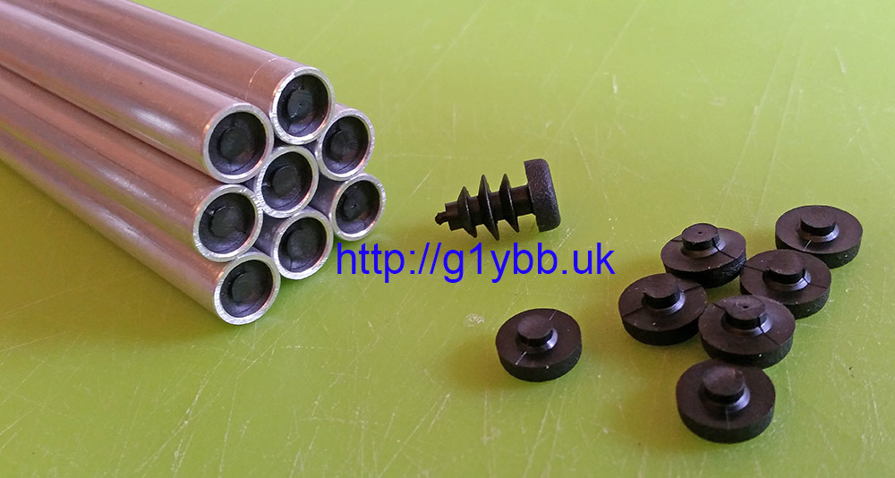
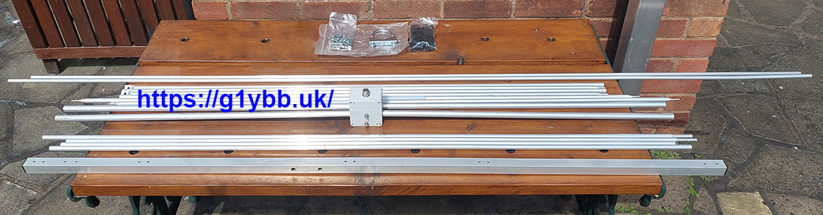 which includes a set of Stauff style element mounts, stainless fittings and a single U bolt for fixing boom to mast. continue reading