I decided for home I wanted a box just outside where my radio sits that I could plug different antennas into easily, so I looked for a tidy way to run antenna feed lines through the exterior walls. Most were running to a large waterproof box that the antenna feeders plugged into but were a lot larger than I wanted. The box would offer a socket and be cabled through the wall and into the back of the radio. I also wanted it to be basically waterproof and compact.
There are many waterproof boxes on the market of course, but none I felt would be ideal. Then a good friend then got his hands on a 3D printer so we decided to print me a box to my design.
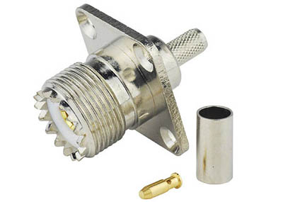
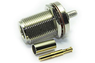
First step is to draw it up. I planned for 2 connector positions (one for each output from the FT-897D) and made it suitable for both single hole bulkhead type connectors and 5 hole panel mount connectors. It will take SO-239 and N-type (my preference) connectors. Both will be cable mount and crimped, which I use in my day job at L Band and above and much prefer to pretty much all other cable fitments for flexible coax.
The coaxes will be fed through a hole straight through both skins of the house through a vertical mortar joint at an upwards angle and the wall plate part of the box fixed to the wall with two fixings into the horizontal mortar line. (My bricks require an SDS drill to drill holes in, plus this is easier to repair if removed later).
A simple slide on cover open only at the bottom extending down past the connectors will shield it from even the most horizontal rain.

Now to send the files over to my very generous friend Paul for 3D printing. He did an initial print of my design exactly as drawn, which took some time for the cover as we didn’t print it the most efficient way up. We got it done, but before I had chance to fit it discovered it was printed in PLA rather than the ABS we thought it was. So Paul decided to redesign it with printing in mind in smaller parts that would be cemented together, having already proven on my Cobweb antenna that this approach was a better plan.
Paul’s design was four pieces rather than my two:
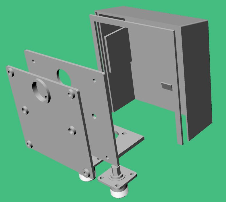
Here is some of the 3D printing and assembly:
The two parts of the weather cover:

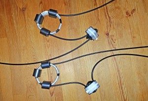
For the feeder from the coax box outside to the radio I wanted to add a hi band and mid band ferrite choke as described by GM3SEK here. I wound one with RG223 which was a springy slippery nightmare and one on RG58 which was much easier. There was no way to get the coils of either sitting tidily with just cable ties so I used masking tape to keep things tidy. As where they will come through the wall is very hard to get to I need to wind them on first and will have to pass the shorter tails out through the wall and fit the connectors outside.
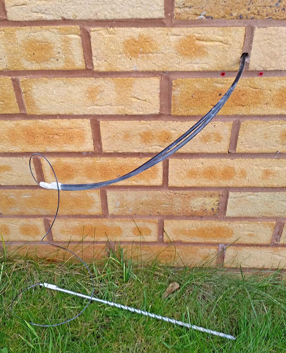
Holes all drilled from outside, and short tails pulled through from inside using the smaller drill and some wire:
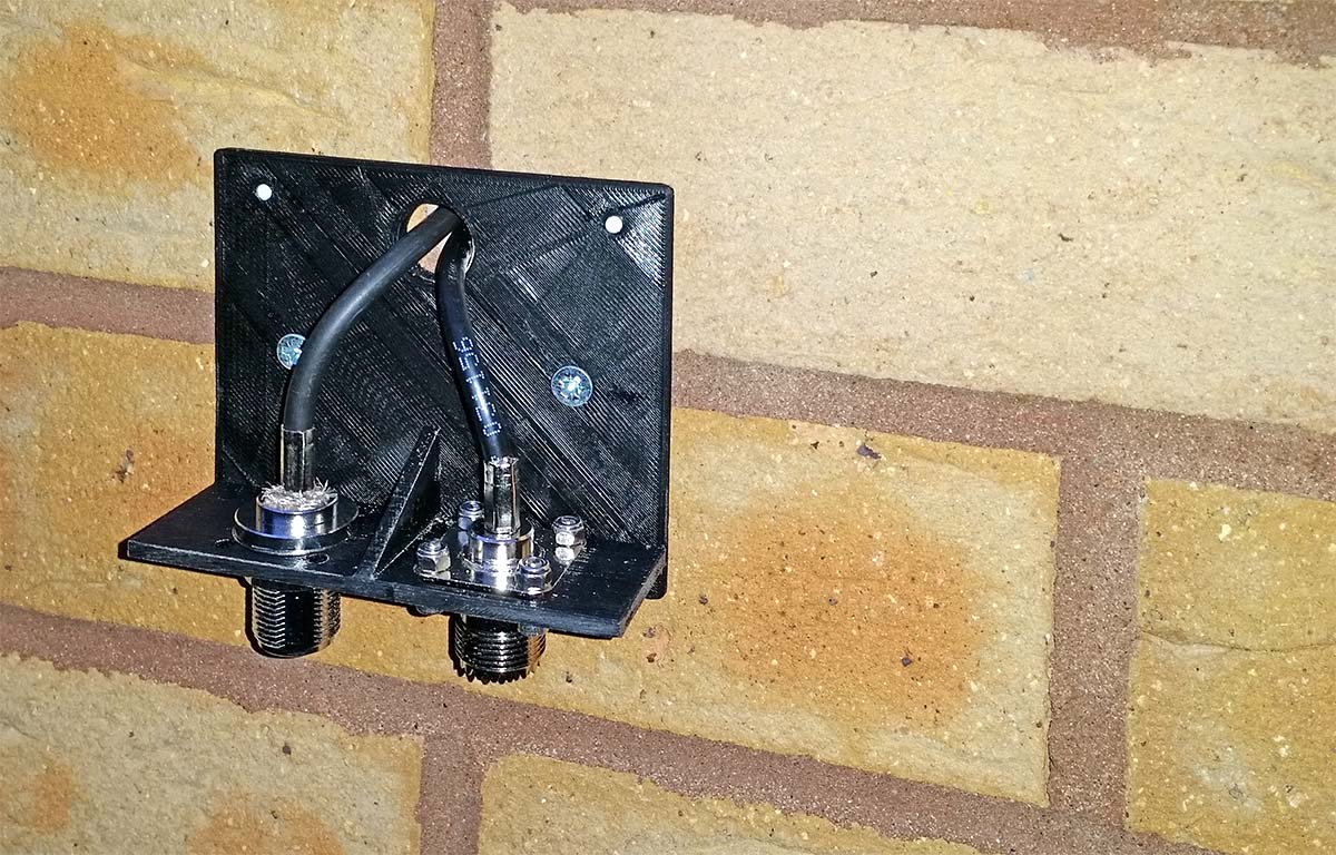
Connectors fitted. As well as remembering to fit the crimp ferrules make sure you feed the coaxes through the hole in the coax box BEFORE fitting the first N-type type connector beautifully. Otherwise it needs to be cut off and wasted. Grrrrr. The final SO239 and N-type socket fitments are not as tidy but electrically good:
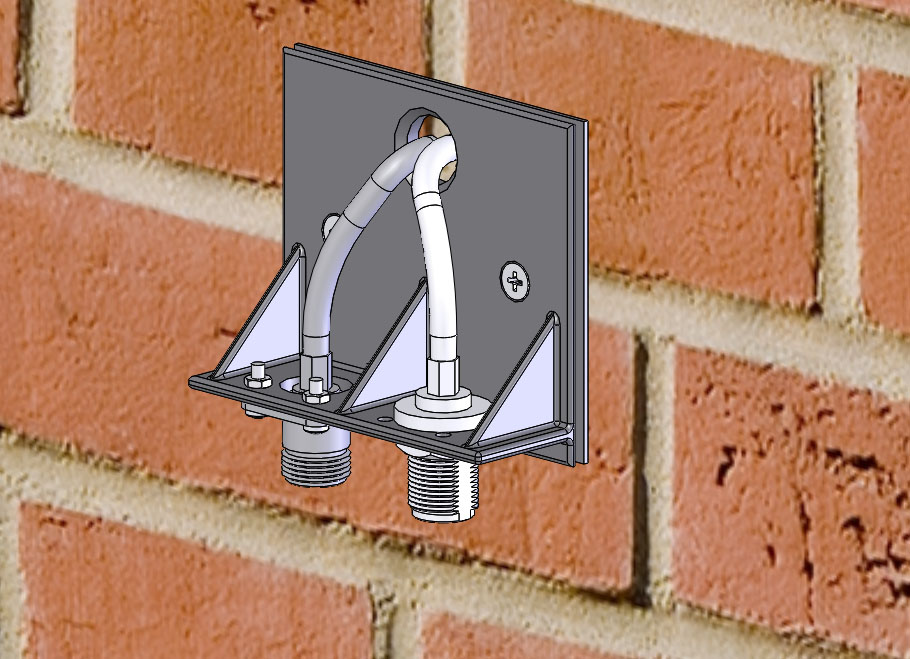
Antenna cable and rain cover fitted. I have also smeared the cables and backs of the connectors with a good layer of vaseline in case any water does manage to run down the wall and down the cables:

From concept to reality. Cool.
If anyone with their own 3D printer is interested is making use of this design my friend Paul has made it available on Thingiverse and Youmagine.