Towards the end of 2016 the rules and days for the UKAC series of RSGB contests were changed. The 50MHz and 70MHz UKAC events were moved to the 2nd and 3rd Thursday of the month respectively. This opened up more opportunities for me as working a Tuesday night contest means rescheduling my Tuesday to a Wednesday and means my Wednesday is busy as heck and it’s at least Thursday before I can even look at the tablet to get the log updated. But a Thursday I am usually free so I can get on another band. As I have no 70MHz Tx capabilities I decided 50MHz was the way forward for me. I have an old home made 5 element yagi we used to use but I wanted a newer better performing yagi. I am getting awesome results with my 144MHz 9 element yagi I decided another DK7ZB sounded ideal.
I chose the 6 element 7.2m boom version as I plan to only use it car portable and it’s only 1m each end longer than the 144MHz yagi I’m using. Also it has a great SWR curve. All dimensions are available on Martin DK7ZB’s site:
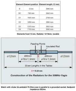
This design only had figures for 12mm elements. That was OK as I can get 12mm pipe clips like I used in the 144MHz yagi. But it turns out buying 12.0mm tube in lengths greater than 2000mm in the UK is exceedingly difficult. It had been suggested to me to use 12.7mm tube as that would be easy to buy in the UK but would require recalculating the element lengths. Not only that it would prevent me from being able to use the fast fit pipe clip I wanted to use. After much searching and asking in various places I had to admit defeat and arrange with Attila at nuxcom.de to ship (at some considerable expense) some 3000mm lengths of 12mm tube, along with several other antenna parts and also some 3000mm lengths of 10mm element tube.
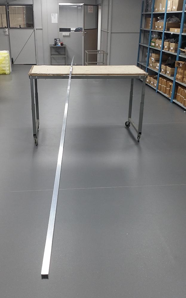
For this yagi, unlike the 9 element for 144MHz, I had no plans to take it backpacking portable so I decided it only needed a 2 part boom. I was easily able to get 5000mm lengths of 20mm boom for this. 20mm is quite small sized boom for a yagi of this size but my element mounting plates are designed for 20mm boom only. I’ll be using truss supports and side supports if required to stop it flexing too much. The 5.1m long 2m yagi was nice and sturdy with its trusses in high winds on the top of the Black Mountains. Although it’s only 1 metre longer each end, it makes for a big boom!
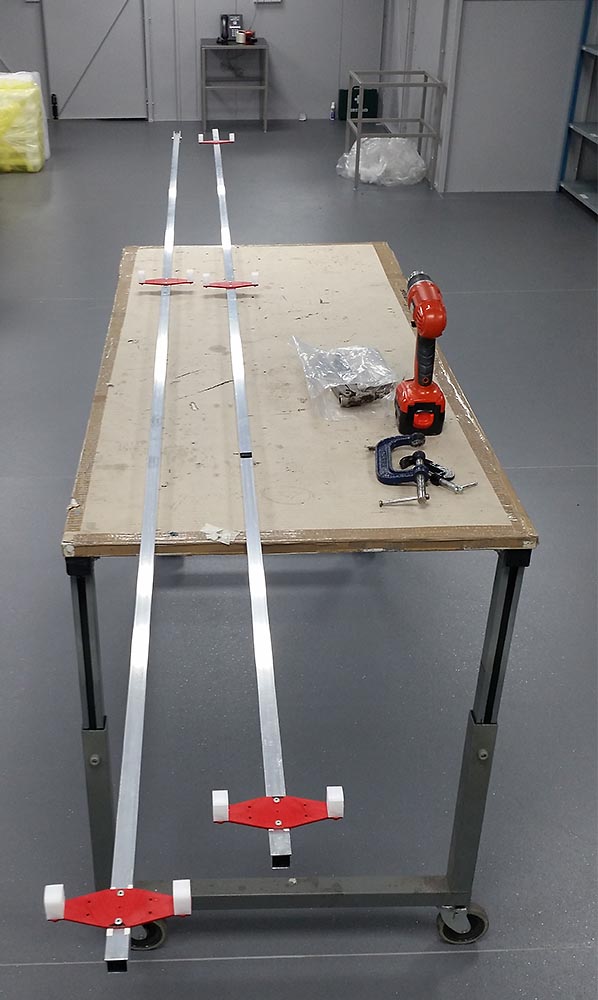
Once the element positions were marked up the 5 parasitic element clips were fitted in the same manner as the 144MHz 9 element. On this yagi the driven is too big for the element clips so that will need a more conventional box:
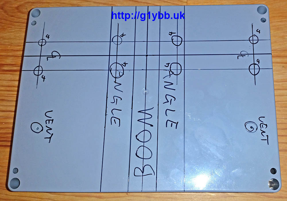
For the feed box I decided to go for a beefed up version of that I did with the 144MHz 9 element. I chose an ABS box from Farnell as it is quite thick walled and with a decent lid should be pretty stiff and is also IP65 rated (before I start drilling it). In order to get a suitable height so the driven element 16mm sections could be on the same plane as the parasitic elements it came in quite large at 200 x 150 x 55mm but that is OK as the driven on this 50MHz is quite big:

Here it is marked up for drilling. Marking needs to be spot on as this is what makes the driven element parallel with the parasitic elements in both planes so is crucial!
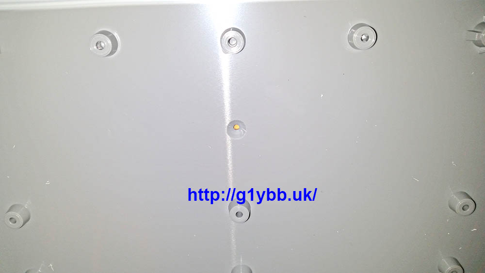
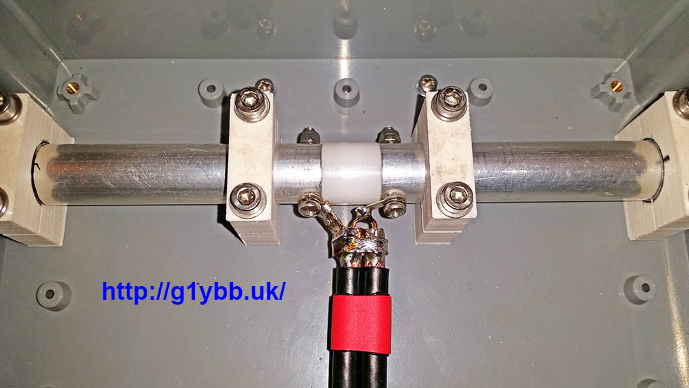
This is the centre point of the dipole box used for locating it on the boom in exact position:
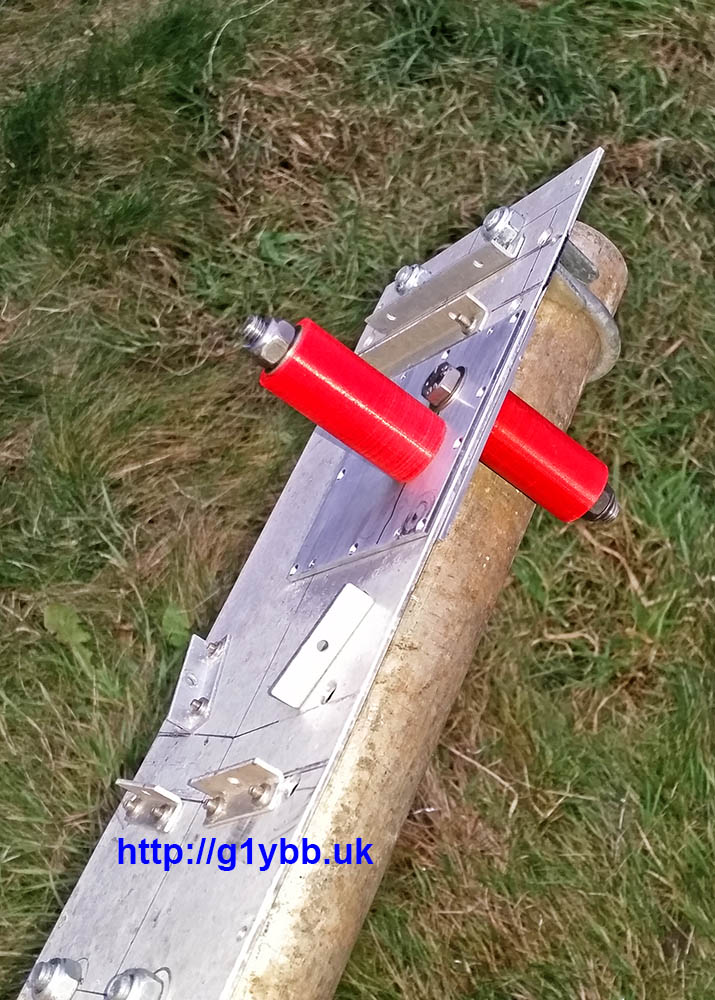
To enable stability and strength for the 3 metre driven element I am using some 19mm angle. The sighting hole above lines up with the centre of the scribed line:

To mount the two halves of the dipole I got my good friend Paul to 3D print some two part clamps in ABS to my design so the centreline height of the driven element above the boom matches the parasitic elements so all elements are in the same plane. Here are the clamps after drilling and fitting to the box with some 16mm tube to check alignment:
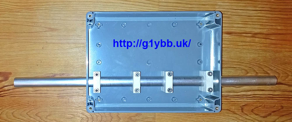
To fit the dipole box I drilled and tapped an M2 hole in the centre point of the boom on the scribed line as seen above and screwed the dipole box in place using the 2mm sighting hole. I then fitted the reflector and first director and ensured they were all parallel and drilled the box to fit the two angle pieces:
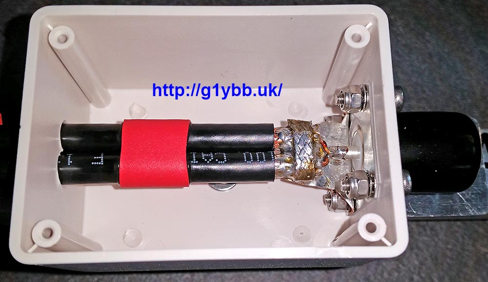
When I bought the element materials from nuxcom.de I also bought their dipole centre for 16mm tubing:
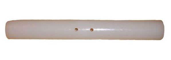
Which is very chunky and strong. But the 16mm tubes fit inside the joiner and I couldn’t see how one would get a good secure contact to the elements. So I got another good friend Ed to turn up a piece that would fit inside the elements like the nuxcom one for 10mm elements does. Here is the mechanically finished dipole centre:

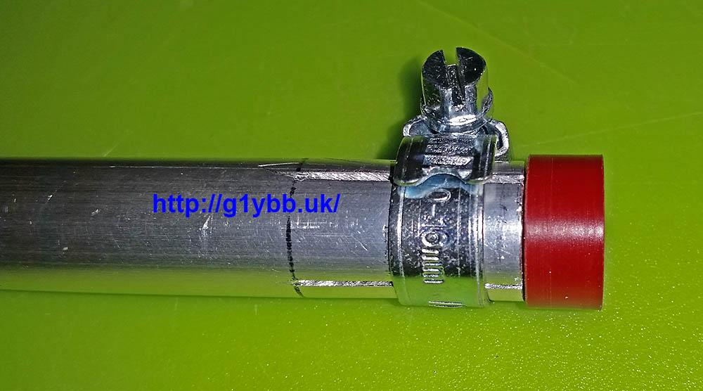
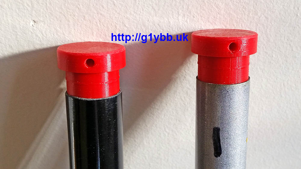
The eagle eyed may be wondering what the red things are in each end. Well as I am using jubilee clips to clamp the 16mm tubes down onto the 12mm main driven element parts, once they are removed for transport (this yagi is for portable use remember) the jubilee clips are free to fall off unless clamped down. So my I got some plugs 3D printed to clamp onto to retain the jubilee clips and also prevent any dirt ingress during transport and storage:
Now the dipole needs the DK7ZB match. I’m using the same WF100 75ohm coax I used on my 144MHz DK7ZB, which is fairly low loss for its size, and is not too big or heavy. Its claimed velocity factor is 0.85 so I worked out the length as so:
300/50.150 = 5.982m full wavelength
5982/4 = 1495.5mm for quarter wave
1495.5 x 0.85 = 1271mm
As before I used a section of boom to tame the curling of the coax to allow accurate measurement and cutting of the lengths:

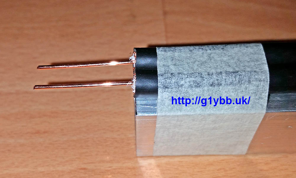
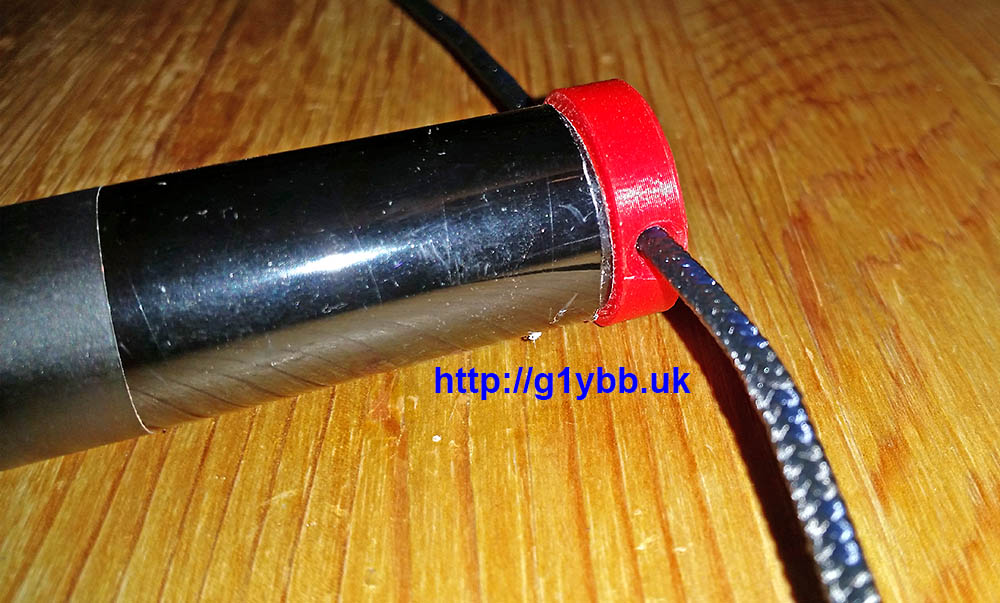
One end of the match fitted:
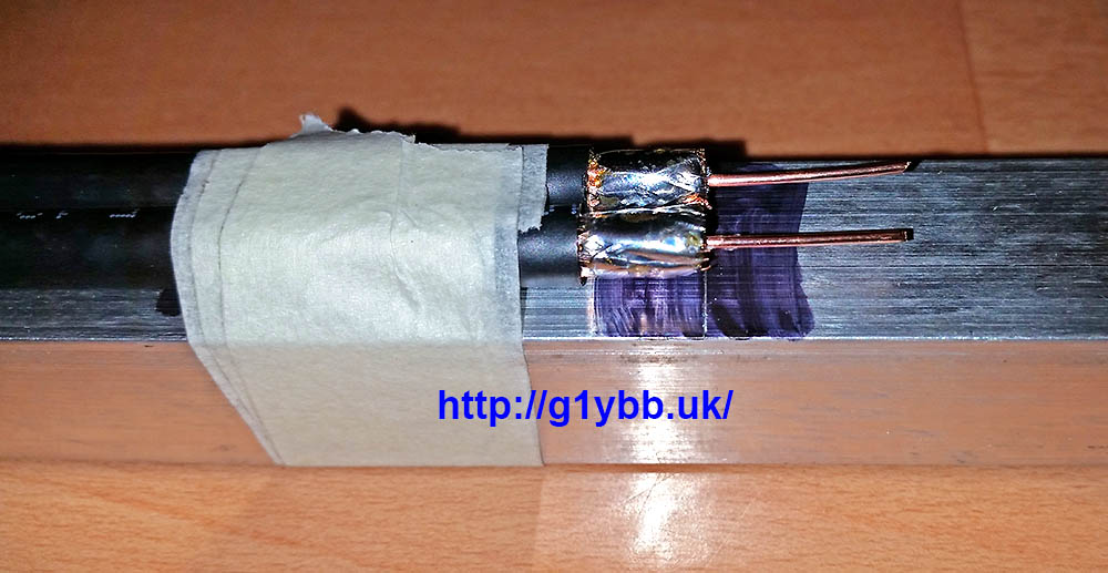
A picture of the process in operation in the ‘workshop’:
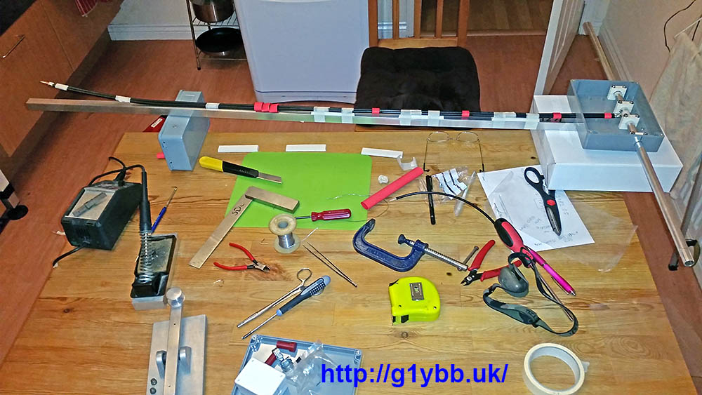
Other end of the DK7ZB match completed:
Apart from the bracing the antenna is pretty much complete except for the fact that the element mounting plates are not really man enough for 3 metre long 12mm elements. They were designed for the 144MHz yagi and only 1m long 10mm elements, which they are perfect for. With the larger elements this is how they were flexing with gentle persuasion:
A quick chat with Paul and he drew up a two part brace that he could 3D print me and soon they were in the post!They utilise the same holes already in the element plates and wrap underneath adding strength without interfering with the element clips at all. I used M4 nylon screws to add extra fixings without adding extra metal, the only metal nut and bolts holding the element clips on:
After fitting the new bracing parts this is the flex with quite boisterous provocation:
Much better!
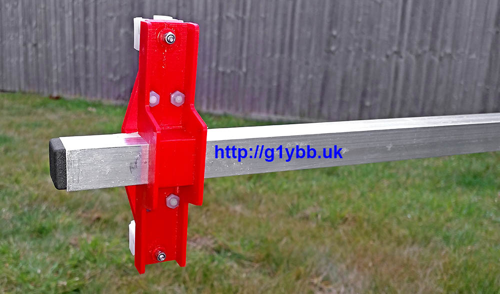
My next consideration is bracing. Long supports were made and fitted utilising the same fittings as on the 144MHz yagi. In fact as I write this I have started work on a 70MHz yagi. All three will fit on the same fittings on the portable mast, and the 70MHz yagi will re-use one of the 144MHz yagi braces and one of the braces for this yagi. The angle of the supports is quite narrow but they do support the boom and keep it straight. This yagi also will need side guys to protect it from the wind. I have several bottom sections of 4m fishing poles left over from HF antenna projects so I utilised two of those. Again Paul quickly produced some parts for me. Some ‘plugs’ to fit to the mast plate to mount the poles onto:
And some stoppers to go in the end of the poles for the 3mm dacron cord, which is very strong and has very little stretch. The stoppers are a good interference fit:
Side guy poles fitted to the mast. These are a friction fit to the ‘stoppers’ and quickly assembled on site:
The sides guys clip onto a plastic bushed (thanks Paul!) bolt on the boom supports with a single karabiner each end. Very quick to deploy:
Next step was to test it! This was done after work on the Wednesday before the first 50MHz UKAC in Jan 2017 the following day! It was reading 1:15 throughout the SSB portion of the band, which was slightly disappointing. There was no time to look into this as I needed to get back home (testing was done in a mountain’s car park) and pack for the next night’s contest!
On the night of the contest the in radio SWR reading was quite low so I was happy the radio was feeling OK about the match and used the new antenna for the first 50MHz contest I have done in 20 years. The yagi seemed to work pretty good and I even managed to beat G4CLA in the AR section of the RSGB 50MHz UKAC January 2017, which I was delighted with!
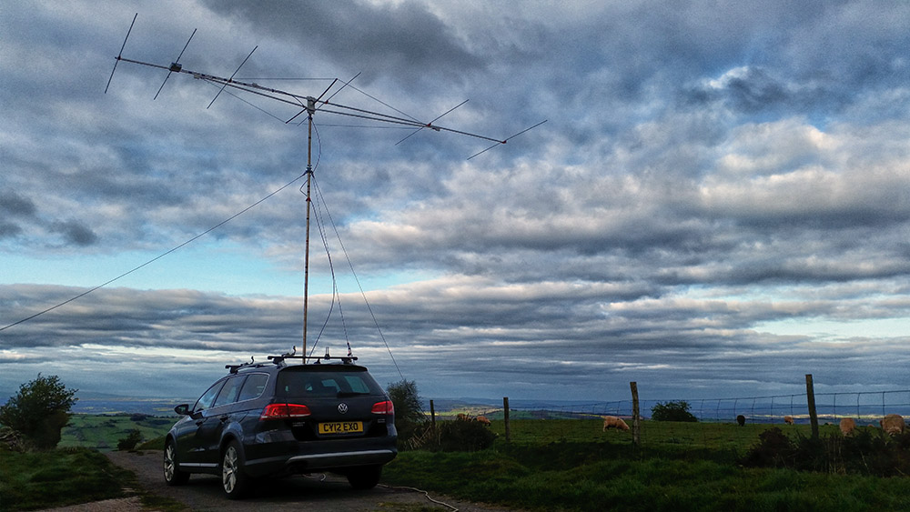
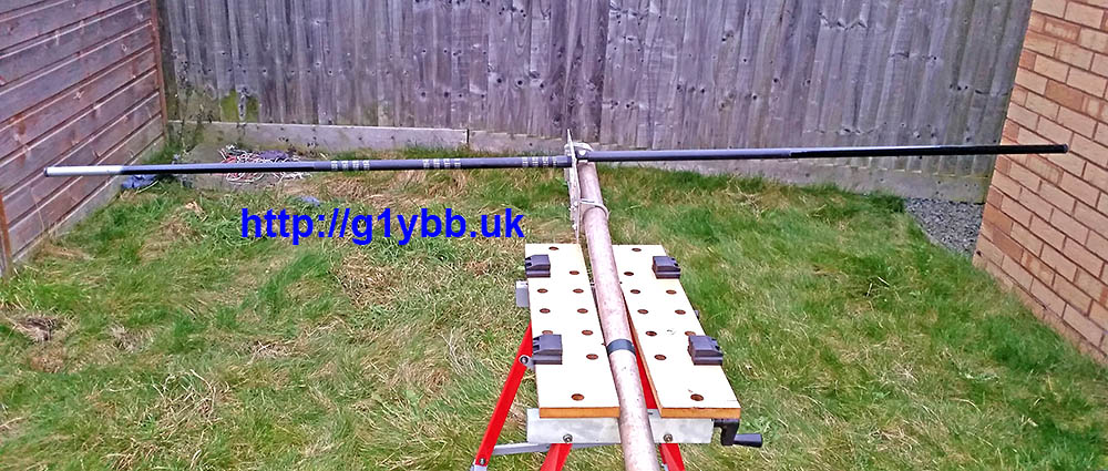
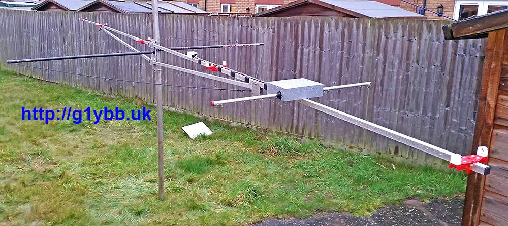
Here is the beam on my portable setup. Longer than the mast is…