As I was planning to resume 144MHz contesting but this time full backpacking style I wanted a decent beam that was suited for repeatedly assembling and disassembling. I have a Cushcraft Boomer and also a pair of homebrew DJ9BV yagis but neither are really ideal for the job. After nearly two decades away from radio yagis have moved on and researched showed the DK7ZB yagis were very popular. His designs seemed ideal for my purpose.
I settled on the 9 element long yagi as it is not too long but with decent gain and also has a good flat SWR curve. The RSGB Backpackers section we wanted to participate in only allows one antenna so stacking shorter yagis was out.
The dimensions are available on Martin DK7ZB’s site:
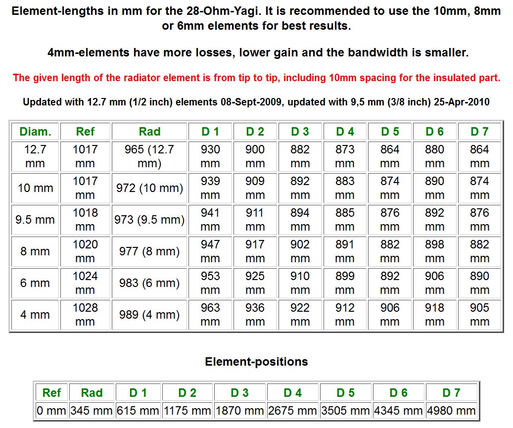
I went for the 10mm elements as a compromise between size and weight and best performance. I was also able to find 10mm clips to suit my intended design.
You can buy some of the DK7ZB yagis ready made and also in kit form, but I didn’t really think the parasitic element mounting methods were ideal for repeated building especially in cold weather. Also the driven element was a problem as it’s not ideal at all for disassembly. There was one example of a driven element designed for taking apart on DK7ZB’s site but I couldn’t find any parts like they were using. I was already building my own lightweight portable mast so I decided I may as well design the yagi from scratch too. So I modelled the full antenna down to every nut and bolt in 3D CAD software. This enables me to know exactly what materials I need and also predict pretty accurately the weight, bearing in mind I plan to backpack this up hills:
To source the main raw materials I found that it was cheaper to buy from https://shop.nuxcom.de/ in Germany than anywhere I could find in the UK! I went for the 20mm square boom and 10mm elements. My 3D CAD model told me I wanted two sections of boom 1.72m long and one section 1.62m long. (After ordering I noticed that is the same lengths Attila uses in his 9 element kits!) I didn’t go for a kit as there were several parts in the kit I didn’t need and I wanted to order a few spares of the elements just in case I cocked up some of the cutting. Nuxcom sell the boom in 1.5m and 2.0m lengths but the 2.0m lengths cost more than double the shipping, so I asked Attila if it was possible to buy 2.0m lengths but have them shipped in two pieces, 1.72m and 28 cm lengths. He did this for me at no extra cost which is good service. The offcuts would be useful for doing tests later.
First building task was to cut the parasitic elements to size. Although I’m pretty good with a wood saw I’m a bit rubbish with a hacksaw and I didn’t want to use a pipe cutter as certainly for the driven element I needed no deformed ends to the tube, so I managed to borrow a mini circular disk cutter like so:
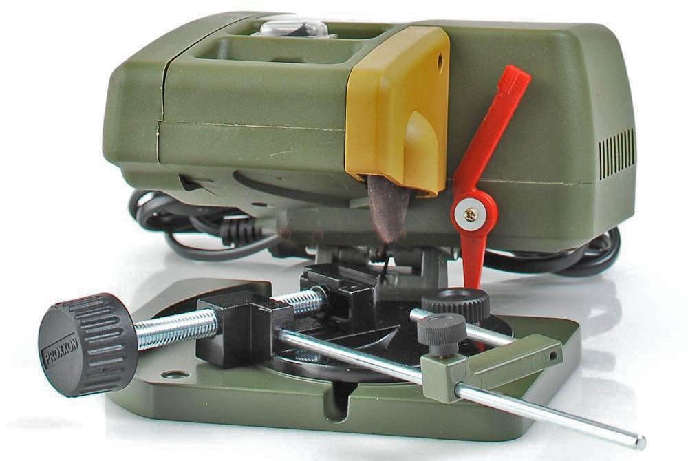
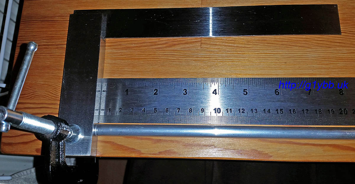
With this I was able to make nice square cuts. To measure them I used a metre ruler (tape measure for the reflector-checked against the metre rule first) butting both up against a stop to get an accurate measurement. I checked that the first mm was a true mm before starting as some rulers have a dubious first mm:
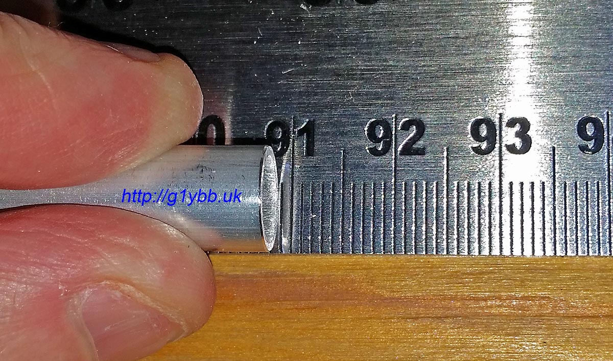
And checking D2 (ever so slightly short if anything by a fraction of a mm):
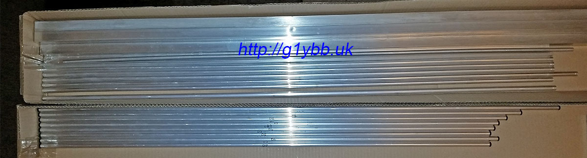
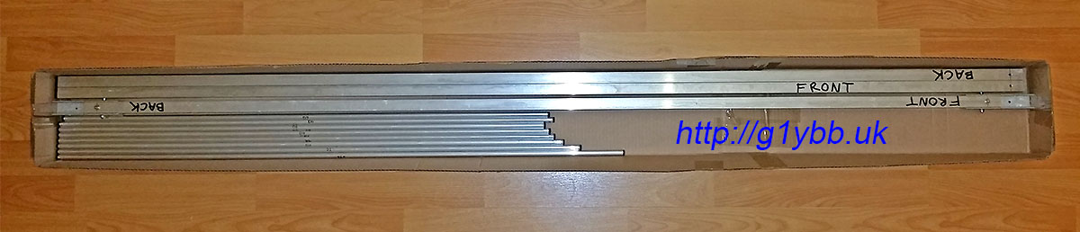
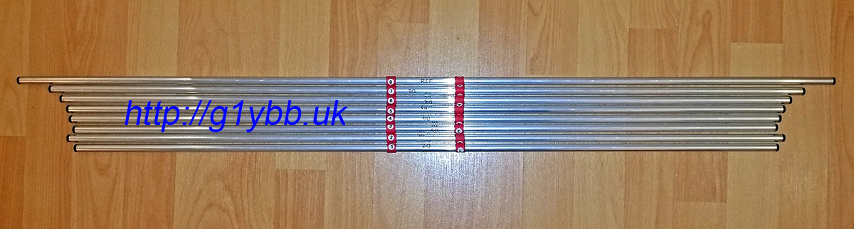
After cutting the parasitic set I fitted end plugs from Nuxcom for a nice finish. (Elements in bottom box, spare elements and boom sections in top):
Next to assemble the boom. I bought the Nuxcom boom joiners and I must say they are very well recommended. The fit onto the 20mm boom sections is a snug push fit and the extrusion is thick enough to be strong yet still light. I got them with the M4 bolt and wing nuts. The one thing I didn’t like so much was the massive hole for M4 which was 6.5mm diameter. However, once I modelled up the joiners and dropped them into the antenna assembly I could see that a 4mm hole at the top of the 6.5mm hole would be pretty much bang on centre of the boom, and mean the boom could not move up in the joiner. I also added a vertical bolt on each side of the joiner too as shown below. That meant the boom section was forced into the joiner tightly ready to drill the holes. I drilled from each side, using the 6.5mm hole as a stop for the 4.0mm drill bit:
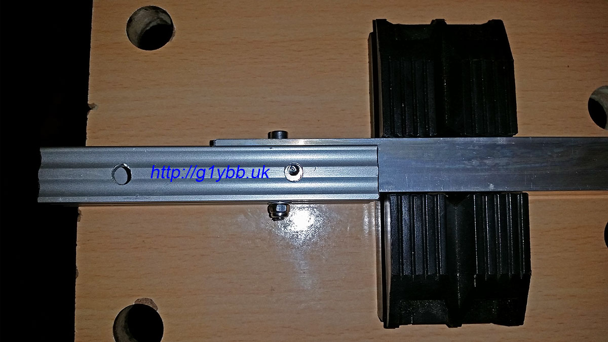
The above picture is showing the boom joiner fitted to the centre section. Both joiners are fitted to the centre section and will stay there permanently so I have used socket cap heads and nylocs, all stainless steel, bolts cut to minimum length. (The four supplied wing nut bolts will be used to attach the end sections on the hill top). With both joiners fitted, the centre section then is pretty much the same length as the outer sections (by design). I also bought the square boom end caps from Nuxcom to finish them off nicely:
The boom was then assembled in my hallway and the centrelines of the element positions scribed on. I used a tape measure masking taped to the boom to ensure it never moved and starting at the 100mm mark on the tape measure to eradicate any errors from the tape measure hook end.
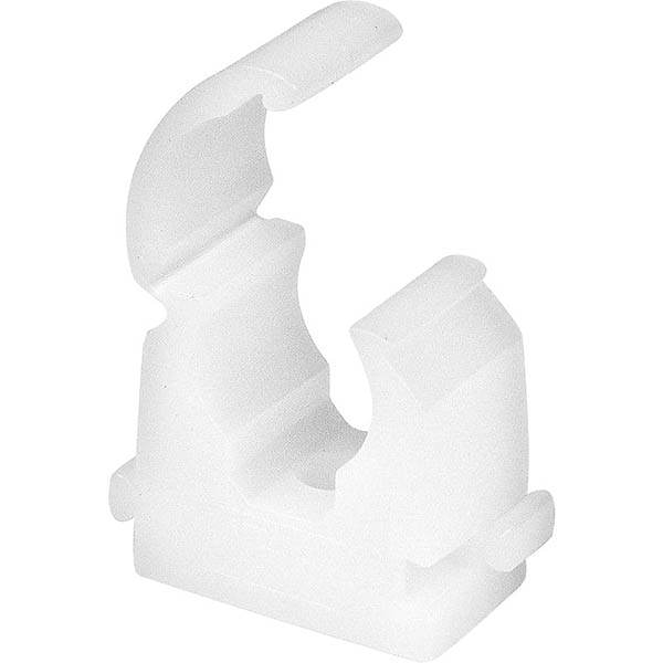
The element clips I needed to find something that was quick to mount the elements and remove them again. The typical single bolt through the centre of the elements I didn’t fancy as it was a bit fiddly especially with cold hands on a windy hill top. My friend found these 10mm pipe clips that were ideal. Snap in and lock, and easy to open again to remove the elements. They will have a finite life but my test piece has had dozens of cycles and they come in a bag of 100 for under £6:
 Another plus point of this is the element centre is a reasonable distance off the mounting surface which means I had good scope for getting the driven element to be on the same plane as the parasitic elements. I just need some suitable plates to mount these on nice and squarely on the boom. My friend offered to injection mould me some rather than my trying to accurately drill out several plates exactly. So I modelled up a mounting plate to be made from glass fibre reinforced nylon which is extremely strong and stiff for its weight. The image shows the underside. The two ridges are to locate on the square boom:
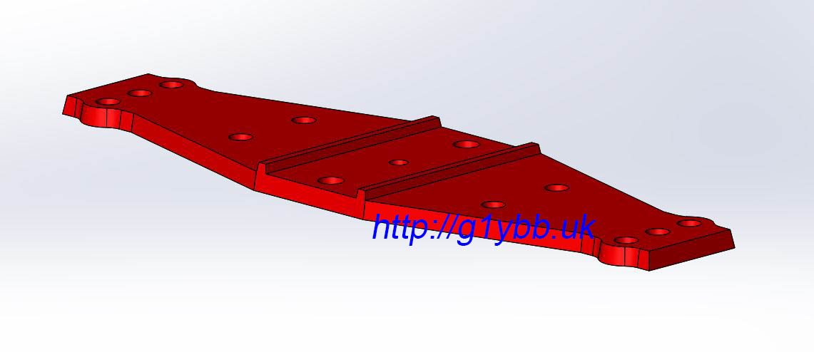
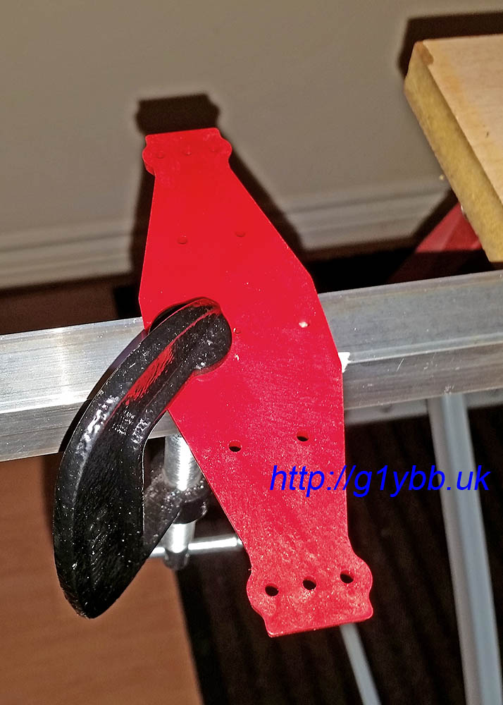
Soon in the post came a parcel of element mounting plates. We decided riveting them on was a secure and lightweight fixing method. The two location ridges on the bottom had a slight amount of play when offered to the 20mm boom which of course would be amplified by the approx 100cm elements so I fitted two tiny strips of masking tape which made the plates a perfect fit. Once the rivets were in it doesn’t matter if the masking tape decomposes away:
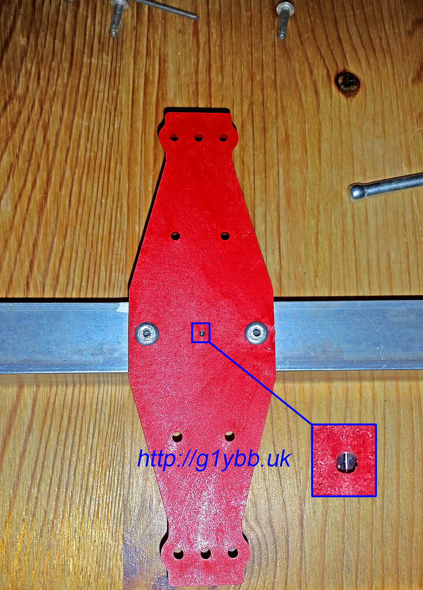
The small hole in the very centre of the element plate is a sighting hole to align the element in it’s correct position on the boom. This was used to line up to clamp the plate on for the drill of the first rivet hole:
Once the first rivet was fixed, the clamp was no longer needed and the 2nd hole drilled and riveted:
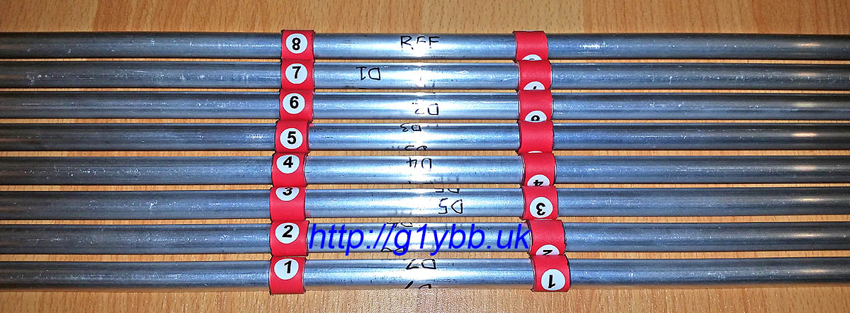
Then a simple case of fitting the 10mm pipe clips and snapping in the elements in the right place centred on the boom. In order to easily locate the element centrally on the boom with out any time consuming I fitted to each element a piece of adhesive lined heatshrink to be positioned between the clamps. I also added some marking numbers for the 8 parasitic elements, numbered 1 to 8 from from to reflector:
Now the easy bits are done, time for the driven element. This was the biggest head scratcher on how to make it suitable for repeatedly taking apart and assembling. I needed to come up with a method that both left the electrical connections to the driven element halves but also enabled me to remove them for transportation. This meant a split in each half of the driven, but how to attach it?
I decided to come up with a system of employing a ferrule in the driven to join the two halves. With some custom made parts it would also be mounted on the same element mounting plate as the parasitic elements and is the reason the element plate is larger than a typical one, although that was also good for rigidity and build accuracy.
When I ordered my 10mm element tubing from Nuxcom I also ordered 1 metre of 8mm tubing to do this. But there were two issues with this. The first was this was the only piece of tubing that arrived with a bend in it. If I had planned to use it as an element I would have had to reject it. As it was I could cut out straight parts to use but the 10mm diameter 1mm wall thickness elements have a bore of about 7.92mm and the 8mm tube an outer diameter of about 8.10mm. No chance of a fit. Out with the calculator and it soon transpired 5/16″ should be a perfect size. I bought some T6 grade aluminium from eBay and it was a perfect fit. Sliding with no slop at all.
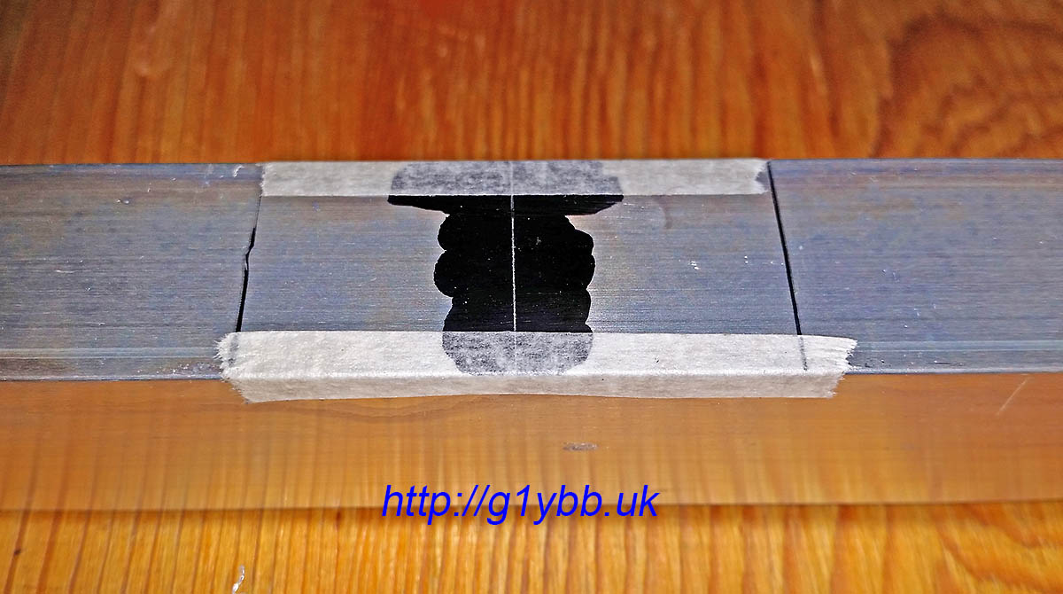
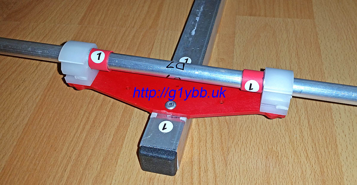
To cut slits in the 10mm tube to compress it with clamps to grip the ferrules I used two 10mm element clamps to mark a dot each end and each side of the clamp and joined them up to make cut lines to follow:
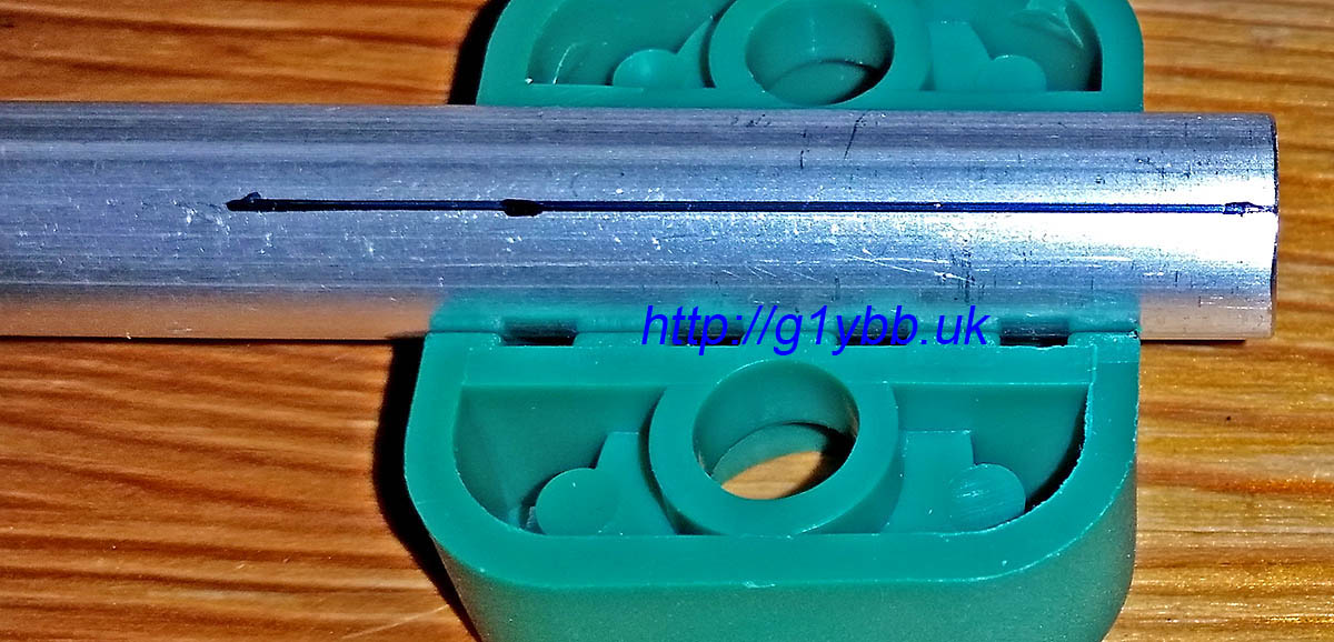
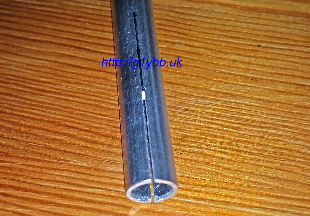
I’m not fantastic with a hacksaw to be honest but using the element clamps above to hold the tube in the vice I was able to cut (from both sides) fairly neat slits with a junior hacksaw (I wanted thin slits):
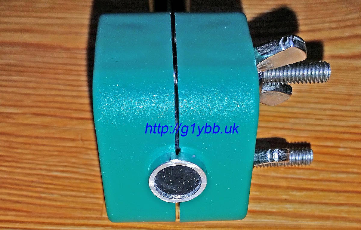
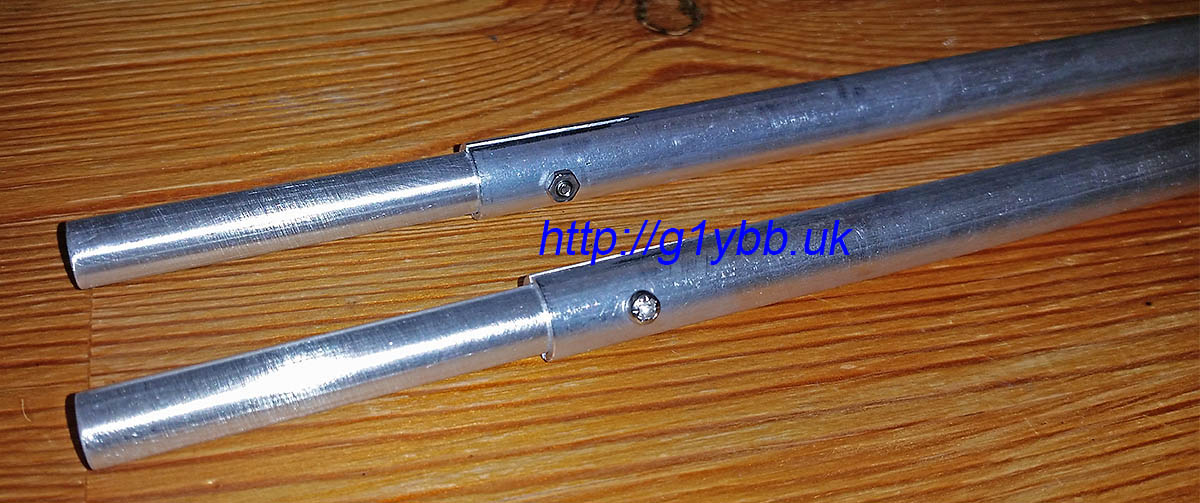
Then it was a case of fitting the ferrules into the outer halves of the driven elements and adding a screw to maintain a good mechanical and electrical grip:
Next to feed that driven element. I decided to straighten out the feed match to take the feed point a little closer to the centre of the yagi. I’m using WF100 75ohm coax which is fairly low loss for its size, and is not too big or heavy. Its claimed velocity factor is 0.85 so I worked out the length as so:
300/144.300 = 2.079m full wavelength
2079/4 = 519.75mm for quarter wave
519.75 x 0.85 = 442mm
DK7ZB gives a length of 440mm for this velocity factor, but I notice all his lengths are in multiples of 5mm so I wondered if he did some rounding down? I hope so!
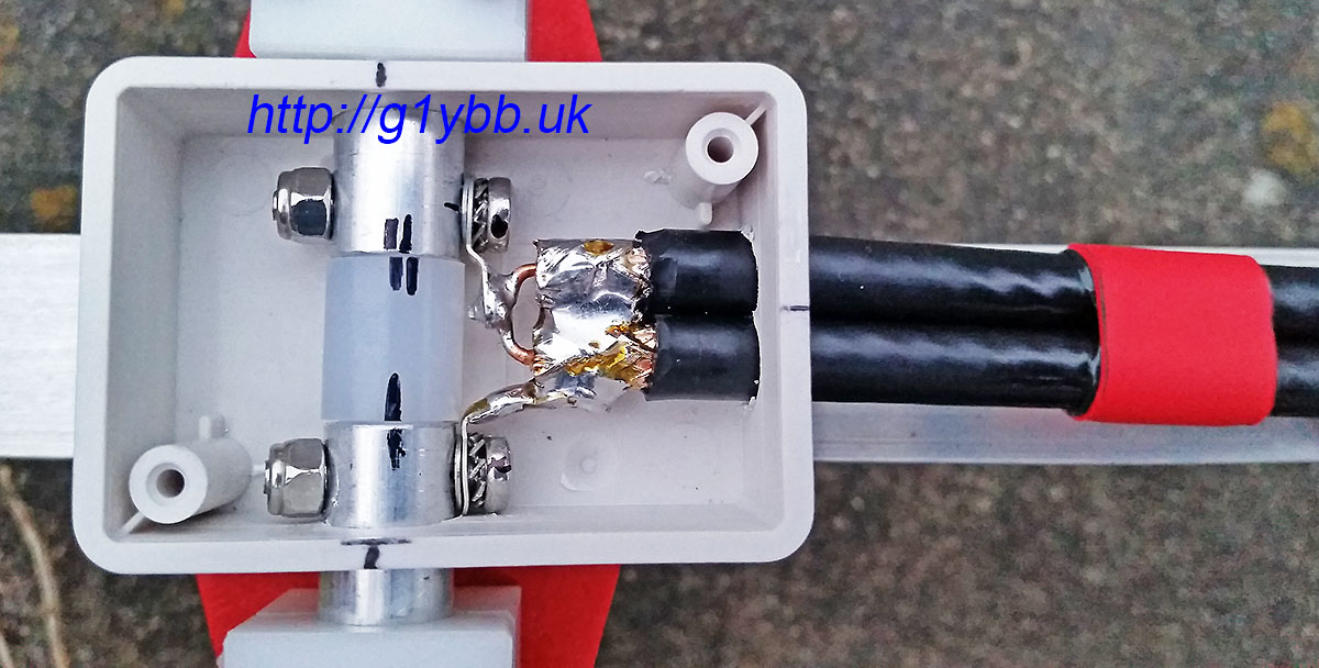
This is the length of the braid. I hate stripping and cabling up coax so did all I could to avoid twisting bits of braid about. I cut the braid and dielectric off square and about 5mm or so of the outer jacket to reveal the braid. With a very large tipped iron of unknown wattage I was able to tin the braid nicely with no apparent melting of the foam dielectric. I then made a small tinned copper plate to bolt to the N-type socket and solder to the braids making a good earth. For good measure I added a loop of braid from some RG223 soldered all round. Then made the inners as short as I could and soldered to the N-type:
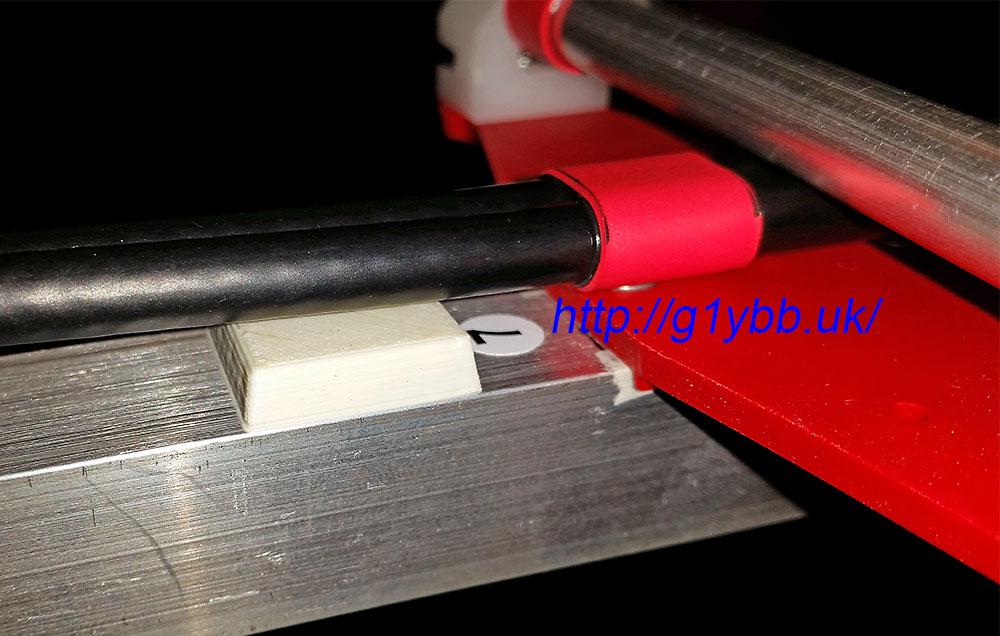
To tame the annoying curling coax I found yet another good use for the short boom offcuts I asked Attila to include. I taped the coax out straight to measure the 442mm finished length:
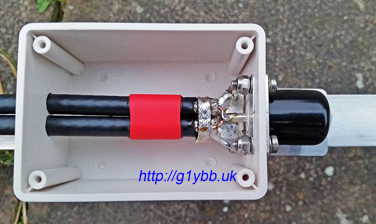
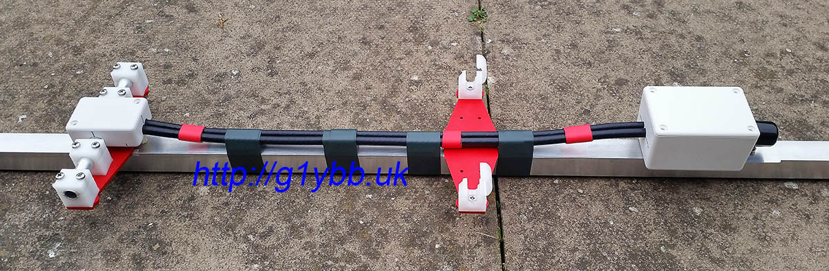
You can see I am using red adhesive lined heatshrink to keep the coaxes tidy and together. In the picture above the tiny box for the driven element connections is threaded on ready for the stripping and fitting of connections. I used a similar method as on the feed end with some copper sheet to join the braids and solder tags to connect to the element halves. This was a very fiddly job but hopefully worth it keeping the connections as short as I could manage:
To support and space the feed off the boom as recommended by DK7ZB (although this is going to be used for QRP almost exclusively) I got some ABS spacers 3D printed which I placed in position and then wrapped tightly with insulation tape. The idea is to keep the coax off the boom (which it is miles away from) but also as far away as possible from the element plate rivets but also as far from the element the coax passes under:
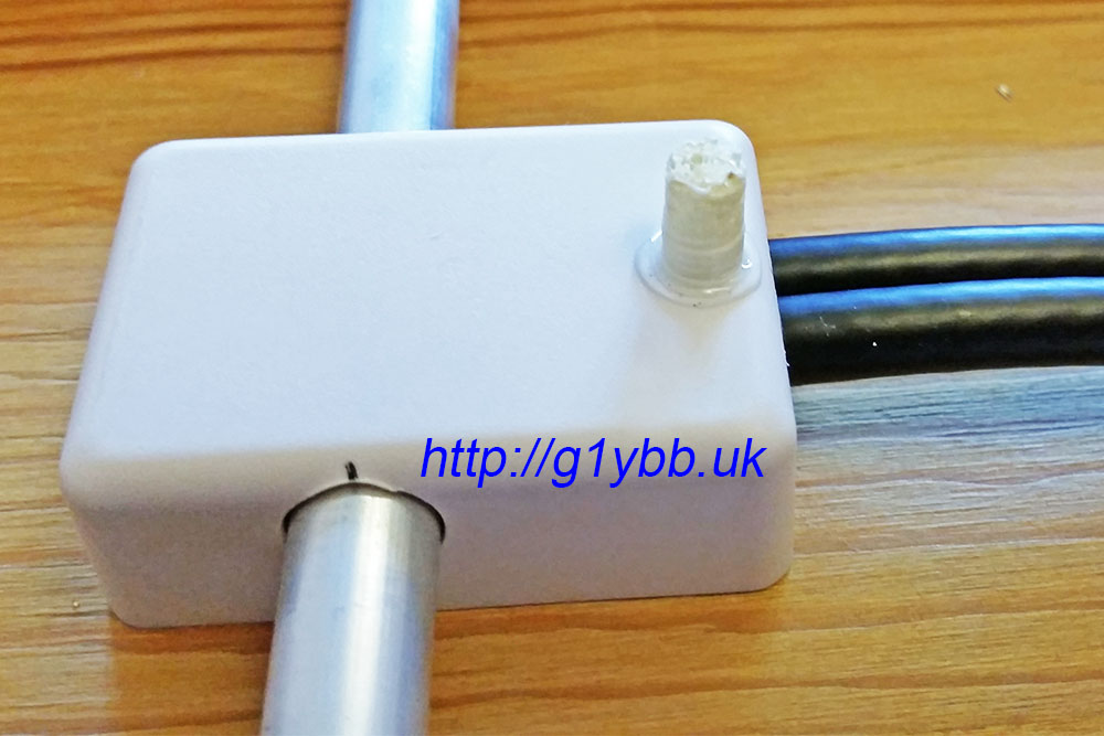
The driven element box is supported solely by the driven element inner pieces themselves, but I added a very small 3D printed pillar to make everything secure:
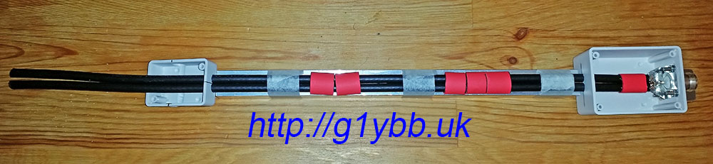
Here is the feed match finished:
As I plan to use this on a lightweight mast section only 20mm in diameter I didn’t think the usual U-bolt clamps would be able to create enough friction to stop the beam spinning on the mast without being so tight to possibly crush or weaken the 20mm ali mast. I bought some plastic 20mm clamps for large yagi elements from Nuxcom to try but they do not have enough friction. So I drew up some half round clamps to be made out of aluminium:
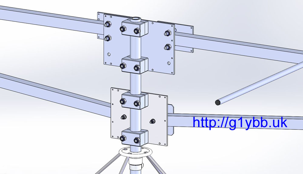
I used a small 3mm aluminium plate in usual manner and bought some 20mm square U-bolts for the 20mm boom itself. As the 20mm boom again is quite small for a long yagi I was again concerned about over tightening the U bolts and creating a weak and potential failure point so I added some small 3mm aluminium plates to allow it to be tightened up nice and tight without any fear of crushing the boom. Here is the finished boom to mast mount. (The two unused holes visible are there to use with the lower 20mm boom mounting holes for a 25mm boom yagi I have):
I used a similar arrangement for the boom support to mast fixings, the aluminium clamps and a slightly smaller aluminium plate. Just a simple M4 bolt per half of the boom support and another plate to help strengthen it all up. The intention is that the boom supports will also help offer a little sideways strength against the wind as well.
To bend up the boom supports I first tried to bend some 20mm square section (same as the boom) in my workbench jaws (seen above in the first picture after cutting the elements). They were not strong enough to bend it! Note this is not a proper vice as such, more of a drilling and cutting bench with jaws. I then thought I might use a bottle jack to apply the force but couldn’t think of anything solid I could jack onto. Then I remembered we have a small 3000lb lever press at work used for punching small holes in sheet metal. I soon made up a jig using a 10 inch square of ¼” steel with some small aluminium blocks and I used the spare offcuts (yet again) to work out the right amount of packers below the centre to give me the bend angle I needed:
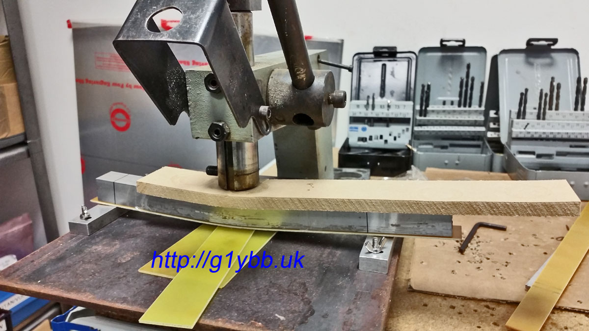
I used 10mm MDF to spread the load from the press and protect the 20mm square tube and a strip of bare FR4 as a bearing and protection to the underside. Once tests were done I quickly and easily put the bends in the actual supports:
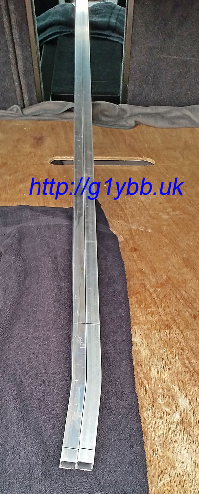
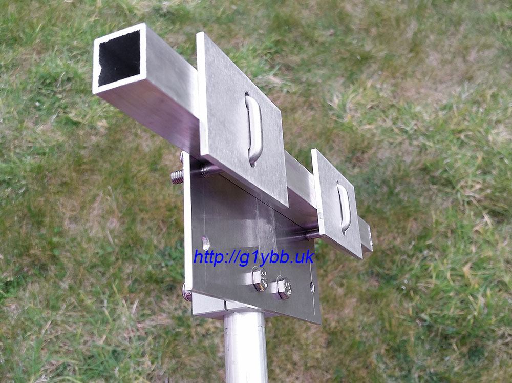
Checking the bends are matched:
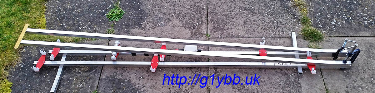
Then just a case of offering them up, drilling holes in the right places and fitting. Finished!
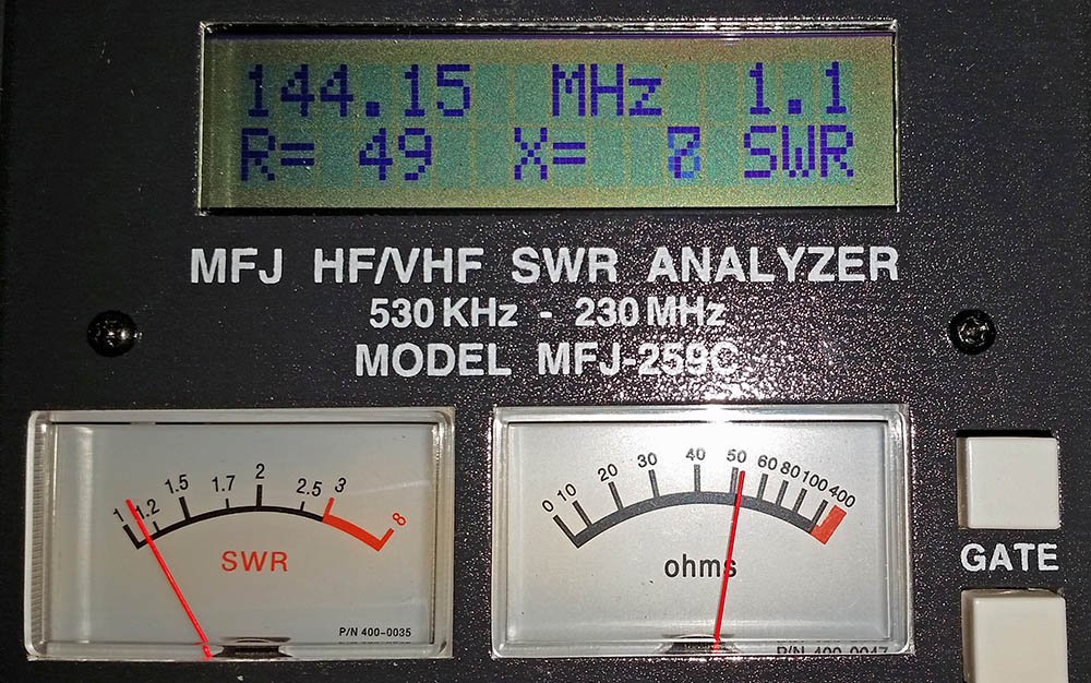
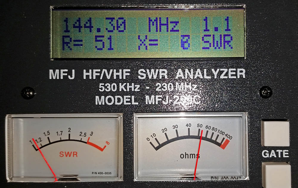
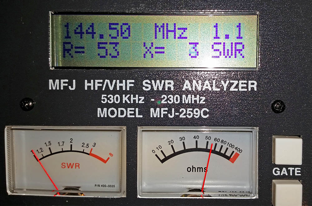
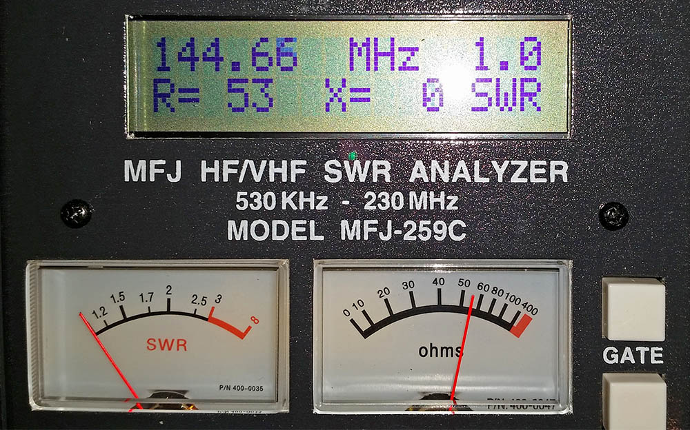
Now for the moment of truth, how does it measure on the antenna analyser? Well to me it looks to be best match at 144.660MHz but is showing SWR of 1.1:1 and 51Ω at 144.300MHz so I’ll take that thanks:
Here is a real time video showing how long it takes to assemble the elements (I have not shown the boom assembly as nothing unusual or new about the boom assembly):
Finally, here is an assembly drawing:
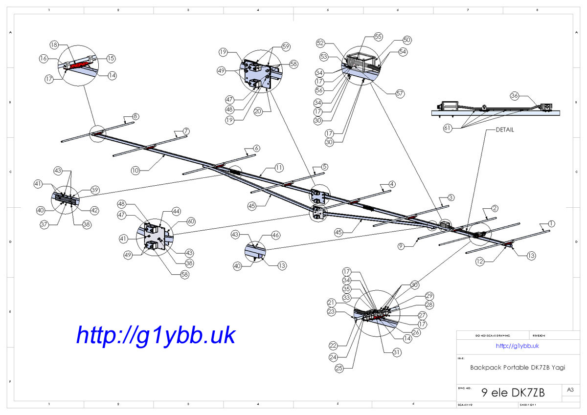 High quality PDF version of assembly drawing
Full Bill of Materials PDF
Only job left now is to take this up a mountain top and do some contesting!
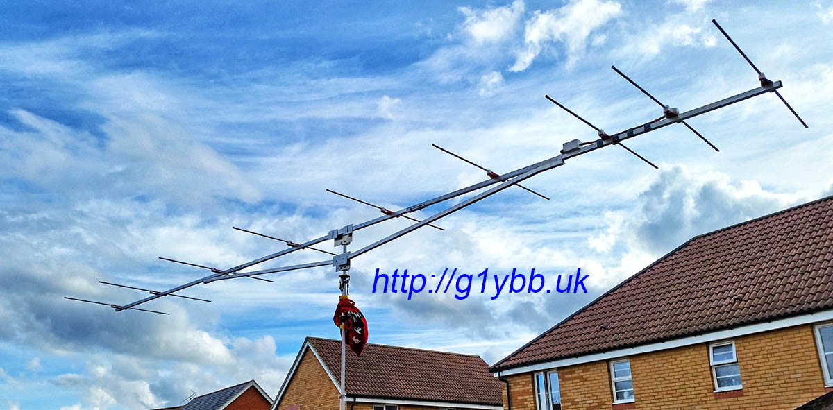
Edit: I have done my first contests with this now and it seems to work really well and I got good reports all round. Even with a low loss feeder the radio was not indicating any SWR reading at all on transit. I have come 2nd and 1st in the low power section of the first two UKAC contests I have entered so I am really pleased with the way this yagi performs. It ‘feels’ even as good or better than our 2x 19 element MET yagi array.