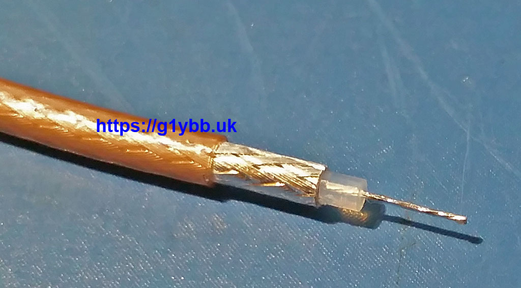
This DK7ZB match cutting jig will enable you to cut RG179 75ohm PTFE coax accurately and repeatably to the length required to make DK7ZB 28ohm matches. RG179 is chosen as it is easy to work with and is best used for antennas that will only be used as part of an array, or lower power use only. It should be good for about 300W PEP on 432MHz. This jig arrangement gives you enough braid to solder to with a very short length of exposed PTFE dielectric. At 432MHz you want to be keeping your ‘tails’ short and tidy for best results.
Design goal:
Reality:
Building the jig.
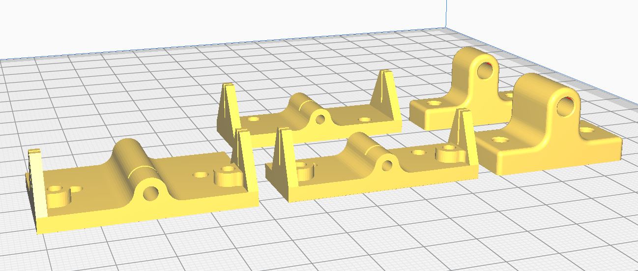
You need to print the following from the files supplied:
1x Part1
1x Part2
1x Part3
2x Part4
2x Part5
I used PLA at 0.1mm layer height and printed them in the orientation that they are used:
Download the RG179 STL 3D print files
I fitted them to a metal plate so I could clamp them to my bench. Holes for M3 bolts are included in all pieces. Small wood screws could be used to screw to a board.
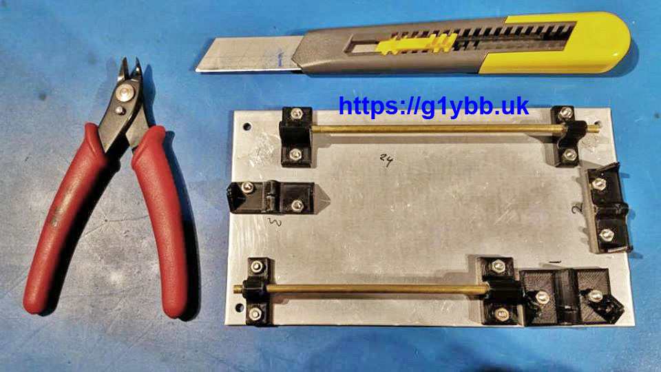
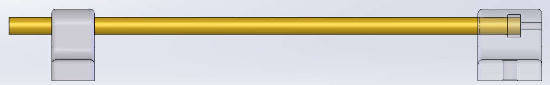
To set the overall length (finished braid and cut for 2nd end) I used 2 pieces of tube the closest size to fit RG179 inside I could find which I found in a model shop and is brass tube 4mm diameter x 0.45mm wall thickness. Code BT4 M by Albion Alloys.
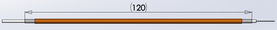
One needs to be cut to 120mm (¼wave for RG179) and one to 132mm. The 120mm is a critical dimension. The 132mm wants to be pretty close. Varying by a small amount is not game over but it means the stripping lengths may not be 100% symmetrical so worth looking out for this.
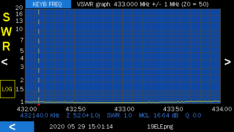
Edit: I have since re-calculated the length for RG179 and other 75ohm PTFE cables and found that it comes up with 121.4mm. I used this to make a 19 element yagi and the match was spot on (bottom of this page).
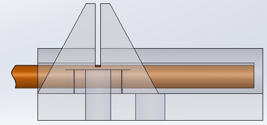
These tubes need fitting into Part4 & Part5. I ran a 4mm drill through both parts to clear the prints for the tube, and a 1.6mm drill through Part4 only for the coax. This hole needs to take the PFTE dielectric with a nice close fit but not too tight. Dielectric should be 1.55mm so 1.6mm drill should be about right.
NOTE: when running a 4mm drill through Part4 (if required) only drill 7mm deep to clear the blue highlight below. The bore opens up inside after 7mm to ensure there is a flat surface for the brass tube to sit against internally:
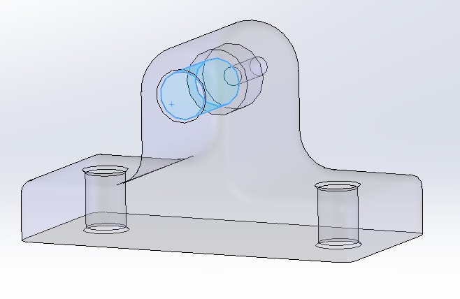
Part4, Part5 and the brass tubes then make assemblies like below. I used Loctite 243 sparingly on the tube before ensuring it was pushed completely home into Part4 then on Part5 when that was fitted. Part 5 is just a support and needs to be about 10mm from the tube end.
Using the jig.
Part1, Part2 & Part3 are designed to be used with a craft knife with the type of blade where you can break sections off, like this one:
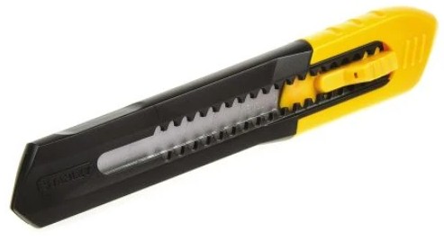
Extend the blade far enough to easily span the two guide slots. Only light pressure with a sharp blade is required. Do not ‘saw’ with the knife, instead rotate the coax. Start with a length of coax about 150mm long.

Step 1 – strip the outer jacket.
Insert one end of the coax into Part1 until it hits the blind end, insert the knife and rotate the coax. I found the jig worked perfectly as printed, but in case near each guide slot for the blade is a hole that will take an M3 grub screw to fine tune the blade height. This cut is the tightest tolerance one.
The outer jacket should be scored not fully cut through. This is to ensure no braid strands are cut. Gently flexing the coax should snap the jacket easily without damage to the coax.
DO NOT FULLY REMOVE THIS PIECE YET.
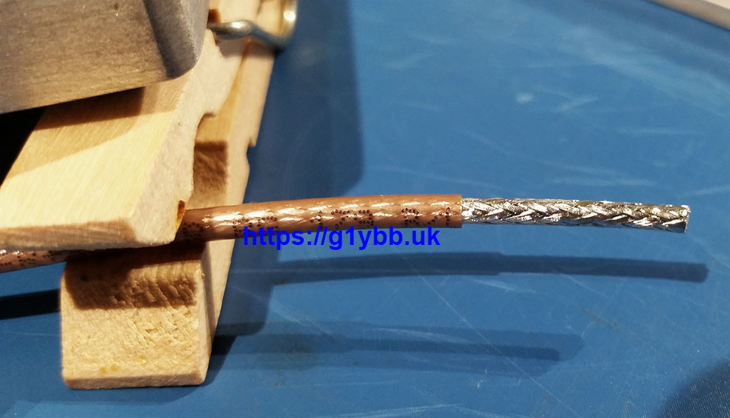
Carefully slide the jacket towards the end to reveal about 10-12mm of braid:
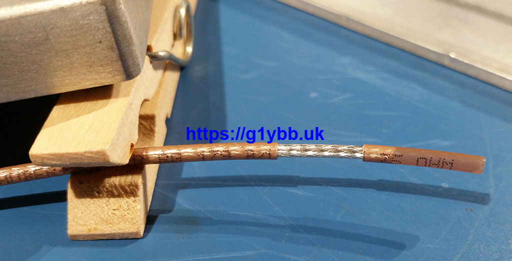 Now lightly tin the braid with solder. Enough to wet all the strands all the way round but not too much to increase diameter. I find ‘real’ solder with a lead/tin mixture better than the lead free stuff. Once done the jacket piece can be removed fully. Lightly tin the rest of the braid:
Step 2 – cut the braid to length
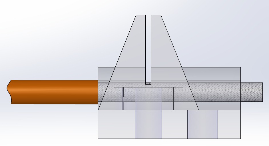
Insert the braid into Part2 until jacket stops and again fit knife and rotate the coax at least once full turn.
Again this will only score the braid, in order to ensure the PTFE is not damaged.
Also again, gently flexing the braid at the score mark should fracture the soldered braid cleanly at the score mark. Braid can now be removed easily.
Step 3 – cut the dielectric to length
Insert the coax into part 3 until the braid stops on the inner stop:
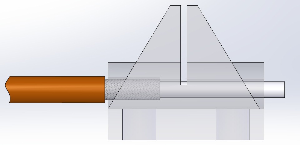
As before, fit knife, rotate coax at least one full turn. The PTFE inner will be scored but should easily twist off, shearing at the score line neatly. Lightly tin the stranded inner conductor.
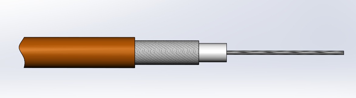
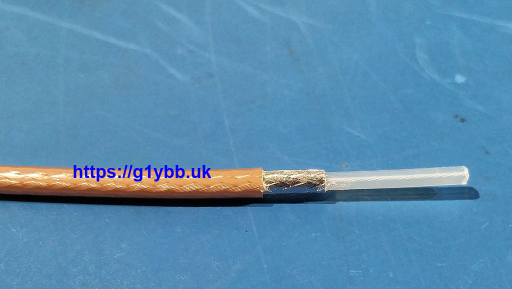
Your coax should now look like this:
Step 5 – trim overall length
Insert the stripped end of the coax carefully into the 132mm tube assembly, rotating it as you go to ensure the PTFE dielectric enters its hole and the braid sits up against the inner stop:
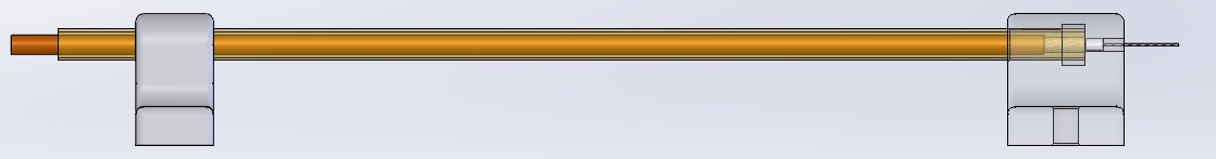
Using flush cut wire cutters cut the coax nicely flush with the brass tube. The neater the better, this will determine the position of the 2nd jacket strip. You may want to grip the coax with the cutters using the brass tube as a guide then carefully pull out the coax from the tube as you cut it so there is some to grab hold of.
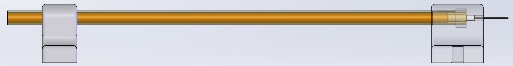
Step 6 – strip 2nd end jacket
Repeat Step 1 above so you have this:

Step 7 – cut 2nd end braid
Slide fully stripped end into the 120mm brass tube rotating it as you go to ensure the PTFE dielectric enters its hole and the braid sits up against the inner stop:
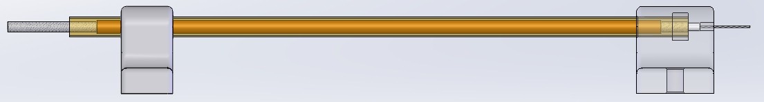
Hold your sharp knife blade on an angle to match the blade’s cutting edge ground angle so the cutting edge is flush with the end of the brass tube and using gentle pressure rotate the coax by twisting the bare braid on the left letting the blade edge roll along the circumference of the braid. You are aiming to score it as in Step 2. Remove from the tube and gently snap the braid at the score line and remove as in Step 2. You should now have a braid length of exactly 120mm:
Step 8 – cut the dielectric to length
Repeat step 3.
You should now have a finished cable:

You can now repeat this process as many times as required and should get extremely similar pieces.
I always ensure I cut my matching segments for all antennas I might use together from the same reel of coax in case of any manufacturing differences.
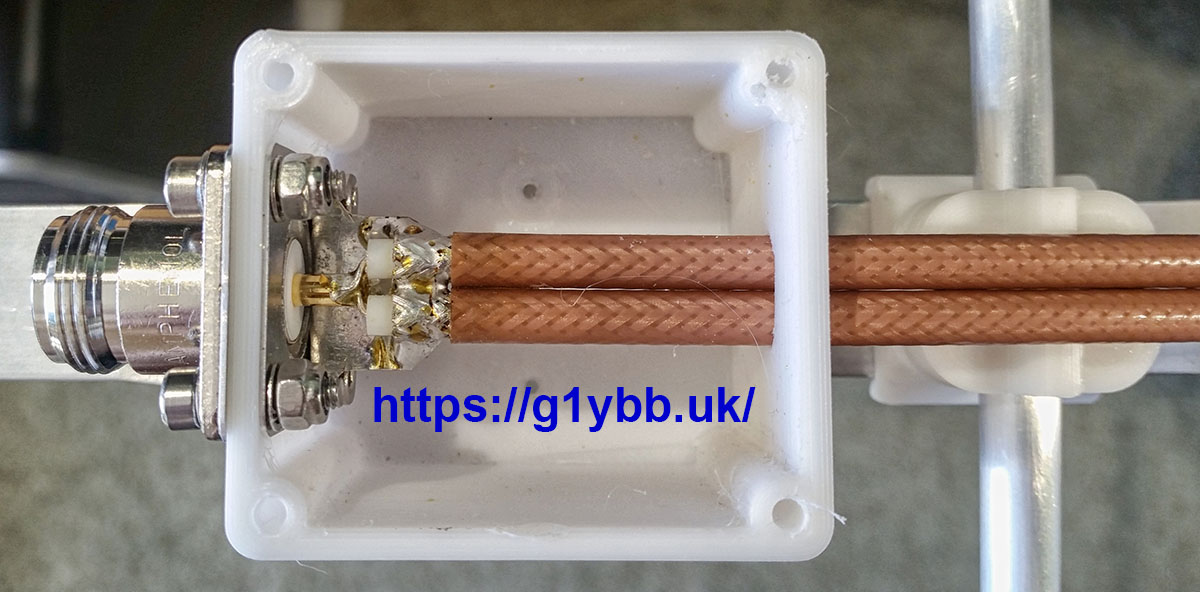
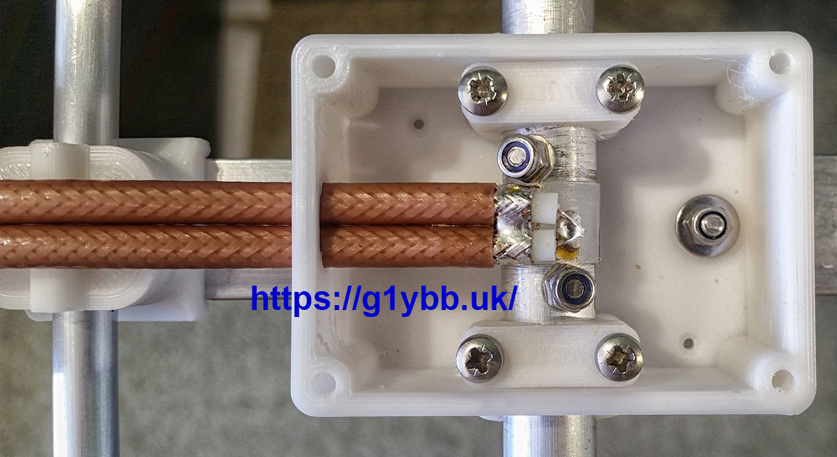
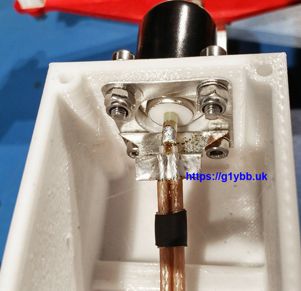
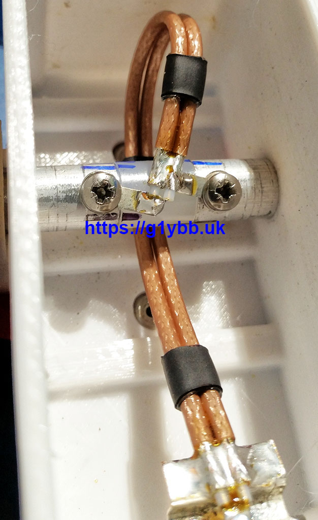
To make the actual DK7ZB match I like to pair the cables with short lengths of adhesive lined heatshrink. One of the few things that tames that slippery FEP jacket. The pics below show how I connected up the short tails.
RG302 Version.
Since making the RG179 matches I have built a version using RG302 for better power handling.
Principal is exactly the same as above except I used 8mm aluminium tube (spare element tube) with 1mm wall thickness.
This is the result I got: