At first glance my arbor press bending brake press modification might not seem amateur radio related but in fact the first job for it will be element mounting plate support brackets for a 10m moxon.
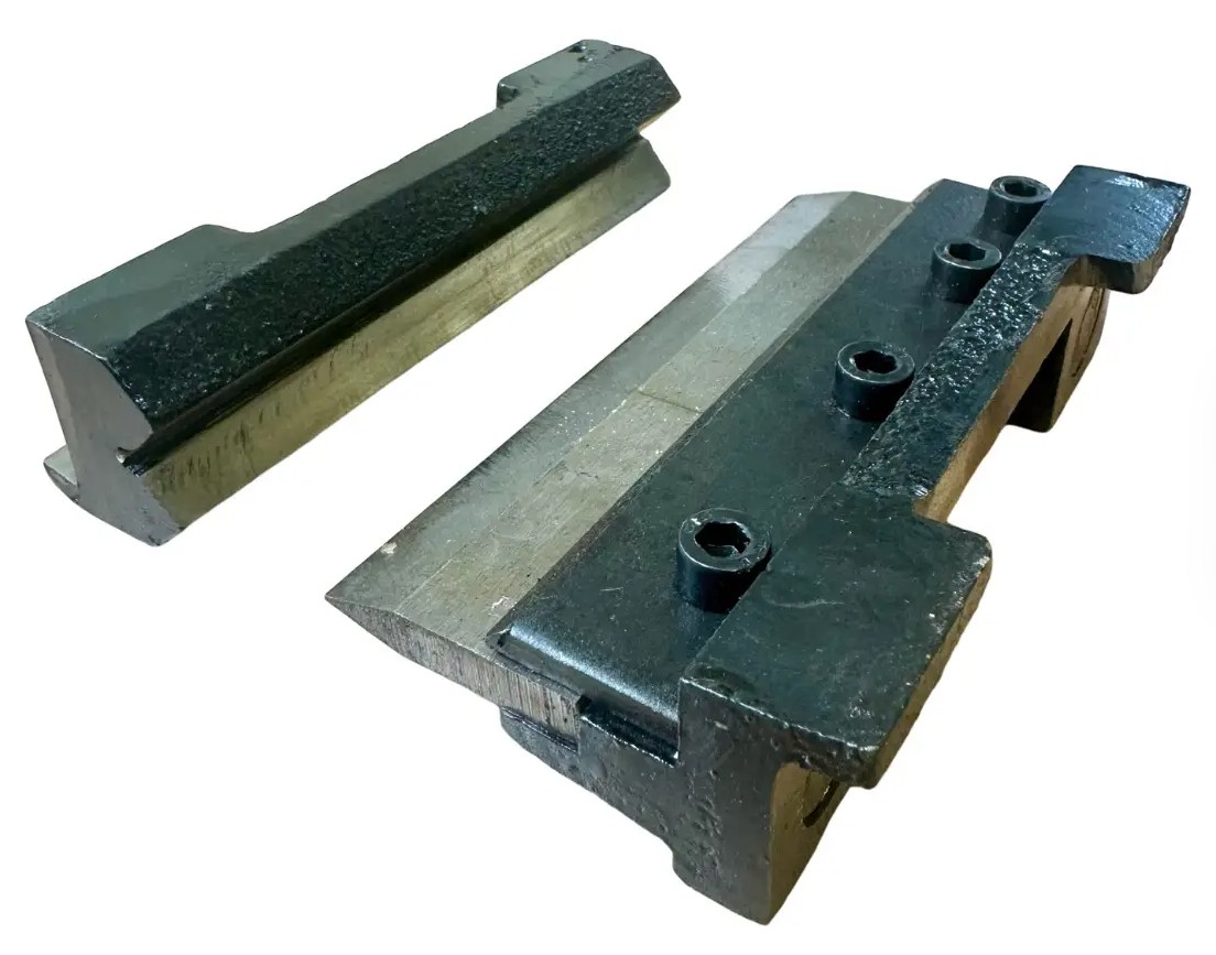
As a hobbyist we have probably all bent sheet metal in a vice tapping with bits of wood etc but it’s always a bit of a poor job at the end, certainly when I do it anyway! But some time ago I got hold of a small vice based bending set like this:
 At the time I didn’t actually have a vice only having a drill press vice but the jaws on that don’t open wide enough to take these so it sat around doing nothing for a while.
I did then decide I needed a vice for this and other jobs so got myself one and did some small brackets for my TMF-3 based DXcommander style vertical portable antenna.
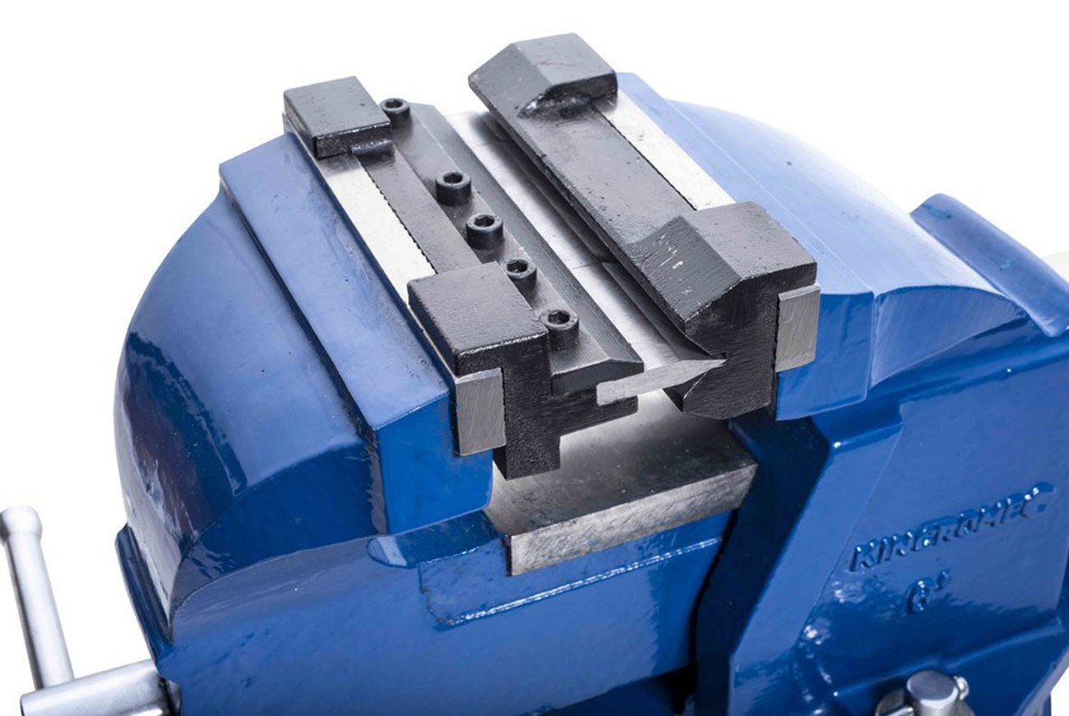 But in making these simple L shaped brackets I noticed a couple of things. It’s really hard to make a fold the exact angle you want at all and even harder to make more than one the same! Also, as my ‘workshop’ is usually the bench in the garden so my vice is packed away when not in use and not bolted down to a bench like most I have to clamp it down to stop all the weight at the front tipping it over. Additionally there is very little ‘throat’ so the longest flange you can make is about 3 inches, the distance above from the bending V to the top of the sliding body part. So I decided I would utilise my arbor press.
The first hurdle was the shape of the bending vee parts which are designed for the vice jaws with no consideration whatsoever given for someone wanting to use an arbor press! How very dare they!
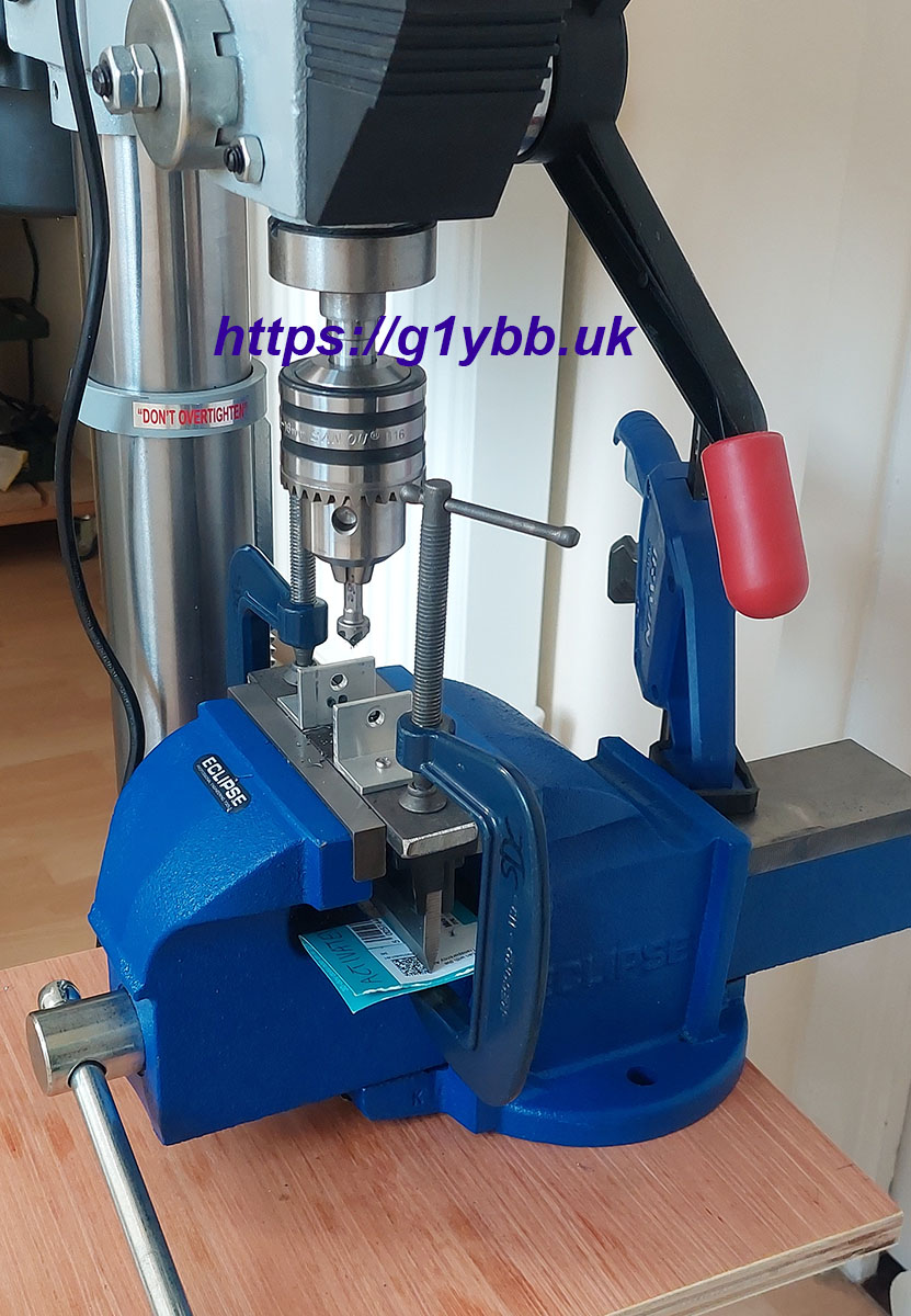
Once I drew up the arbor press ram and the punch of the bending set I came up with the idea of bolting a thick steel bar to the the ram then the bending punch would stick to that. Initially I thought I would drill up into the end of the ram as I see several people do to mod their arbor press for tooling but I didn’t feel a single hole would be good enough and there wasn’t much space there for a pair of holes. Also I decided I wanted to keep the press face flat as I use it for things like pressing in The YBB Washer so I went for a bolt through with brackets:
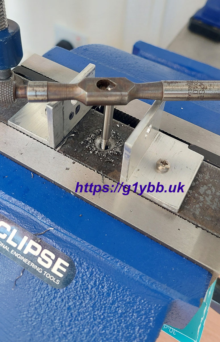
 I then decided I wasn’t happy relying only on the magnets to hold it in place so I decided to drill through, tap the body of the vee punch and screw it to the steel bar. To do this and ensure everything was well lined up I decided I needed to clamp it all up and drill them together. The vice came out and also the speed clamp to stop it falling over! I used the vice to press the locating ‘ears’ to the side of the steel bar and G clamps to press the magnetised face to the bottom of the steel bar, drilled pilot into both, tap drill into both, clearance hole into bar, tapped then countersunk the screw hole all in the vice.
Next was the vee side of things to sort out. Initially I planned to use the metal half from the kit but it meant making something to support the odd shape and screw those together. Much easier was just to 3D print a new vee part.
I happened to have a piece of 8mm thick steel pretty much the perfect size for the bed of the arbor press, one of those “one day this will be useful” keepsakes. This would make a strong base for the bending vee. I wanted a guide fence as well to make the bends perpendicular to the side of the metal. This is a different arrangement from the CNC brake presses at work (yes-I actually work for a sheet metal company with a full manufacturing facility but I rarely ever go in as I work from home) where you have a variable backstop that sets the bend width and you push the metal against that and make your bend. Here I will be relying on marked bend lines and the fence to keep it square. I wanted the fence movable so that for narrower metal than the width of the punch and vee I could move the fence so the metal centre was below the ram centre.
Additionally I wanted the fence to also act as a guide to ensure the punch and ram came down centrally in the vee as the arbor press is not a precision machine.
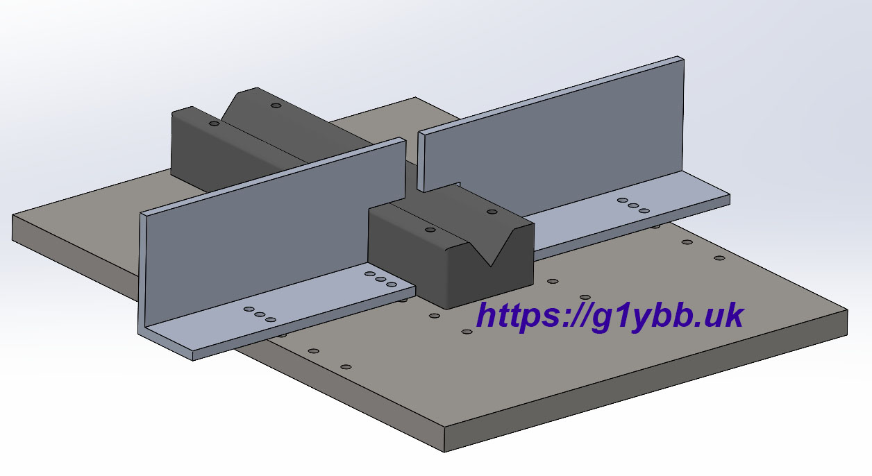
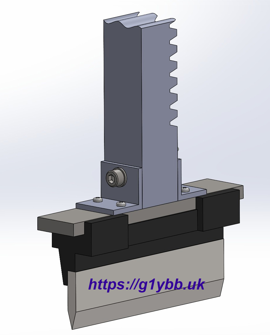
Above is the 3D design of the arrangement. As few sets of holes in the steel plate as possible (as it is there is a total 176mm depth of 3mm holes in steel!) and sets of holes on smaller pitch on the aluminium angle fence. And the gap between the two halves a little wider than the punch.
It turned out that my handy plate was not square. It was clearly a length of 150mm wide steel bar chomped into the length as the sides were parallel but the ends were not. This meant accurate marking of sets of holes for the fence and vee was very hard with a square. Instead I printed a drawing 1:1 scale with cross points on all the holes and taped that to the steel plate and used that to punch to. I have successfully used the same method to make the hub plates on my lightweight 20m moxon which you can see would have been a nightmare to draw out!
So here is the real thing after drilling:
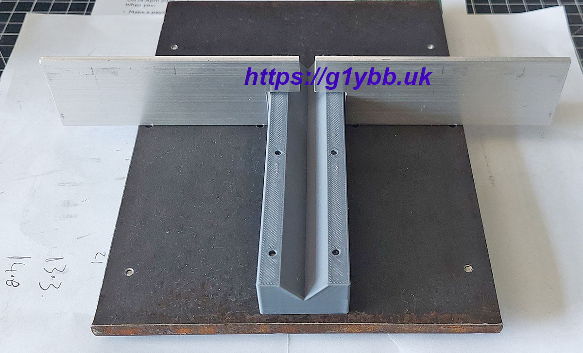 The bending vee is printed in PETG which should be more than strong enough, I have seen people bending thick steel with PLA bending sets and I have also mounted them with overly long M3 screws that are just a mm or so short of the top face.
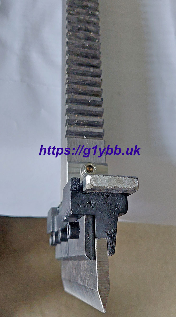
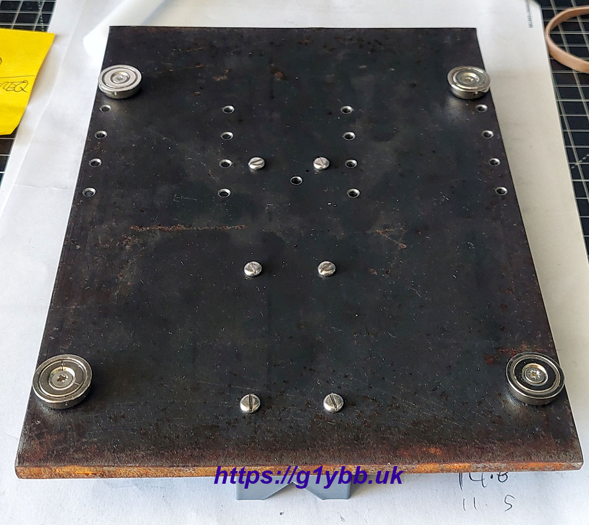
Initially my plan was to drill and tap some fixing holes into the bed of the arbor press to mount this plate but I realised the shape would not allow me to get a drill in except from below. So I changed my mind and have gone for a different approach. I recently bought some magnets to make a digital DRO for the mini lathe as seen here on my friend’s youtube. This style of magnet focuses the field and are quite strong I decided they would make good magnetic feet. A word of warning, don’t be too enthusiastic tightening them up, you can see I have cracked one! The actual down force from the ram will be taken by the steel outer shell of the magnet so I am not worried about further damage.
 When fitting the baseplate to the arbor press I will insert the vee into the point of the punch then lower the ram until the baseplate sticks to the arbor press base so that I know it is in the correct spot.
We’re almost there, just one more ‘issue’ to solve. The very first parts I want to make have four folds that need to be the same so the two ends are in the same plane and that plane is parallel to the centre part as so:
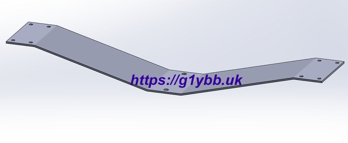
No way am I going to be able to guess this. Back to the 3D drawing board for the solution.
The bend I need for this part is only 15° which is nothing for the brake press. Putting the bracket into the brake press assembly shows the minimal amount of movement required. My solution was simple and removed the need for any complex depth stop arrangements. A simple slide in depth stop in the V will make a repeatable mechanical stop. I allowed a very small gap for spring back but these small aluminium parts are not springing back much:
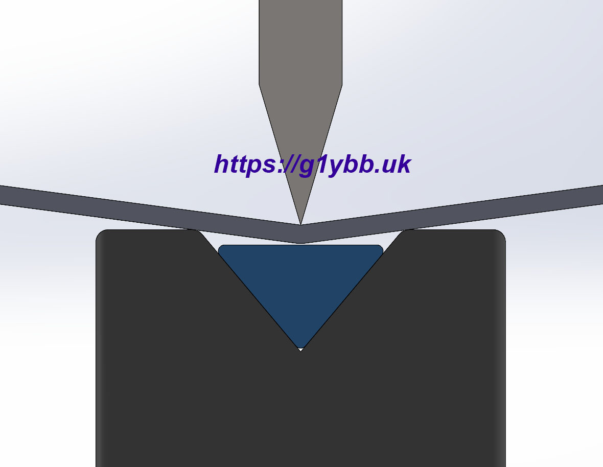
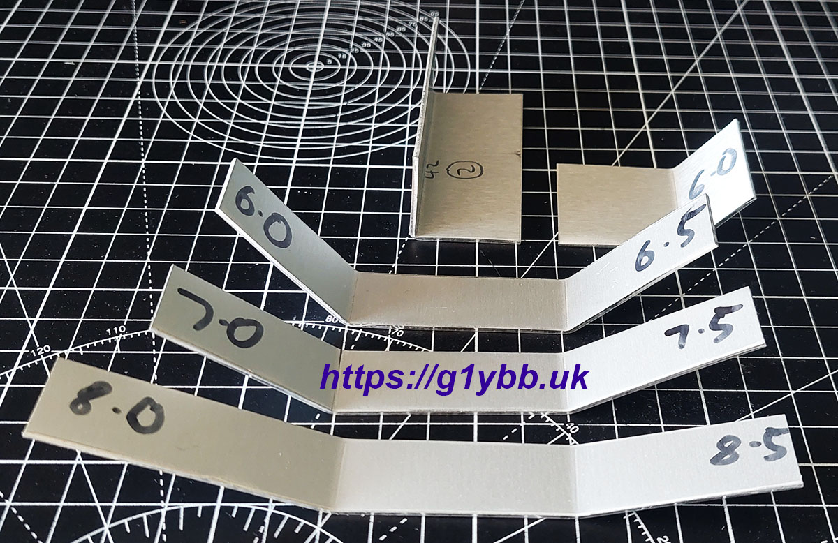
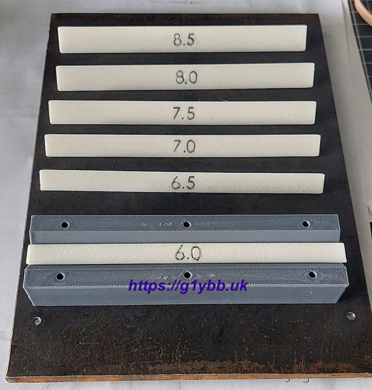
A set of these depth stops will give me various angles, and a tiny one will give me the 90° bend as I made the vee block angle 80° to allow for spring back. Here is my first set. I missed a trick here as I have a Bambu Lab P1S with AMS now and could have printed the numbers in another colour but marker pen works..
So now I am set and ready to bend up my brackets. (Almost- I need to come up with an improved clamping system on my hand guillotine to stop the sheet moving…)
Here is a quick first go. You can see from this that unlike the vice based version at the start we have almost unlimited length of material we can bend across:
And here are the first test bends. The 90° is over bent as I hadn’t made the stop for that yet. The 7.5 (the numbers are the height of the triangle in mm) turned out spot on for 30° bends I needed for one bracket and 8.5 almost for the 15° bends. I made an 8.6mm one which is shown in the earlier 3D image which gave me my 15° bends nicely.