As I had a terrible job managing DXlog RTTY setup on IC-7610 (NOT DXlog’s fault – it’s the RTTY side that is the issue!) and I know others have given up, I thought I would share what I did and my settings.
I AM NOT AN EXPERT – BUT – I have got it working very well in the end.
To start, this is on Windows 11 Version 24H2, however, I got it working on Windows 7 SP1 prior to this, noted all my settings down and got it working on Windows 11.
DXlog I am running V2.6.11 which as I write is not the current version but it is not broken, I shan’t fix it just yet!
I’m sure those running N1MM+ or WinTest etc can find similar settings. As said the biggest issue I had was knowing what settings to use.
Radio end.
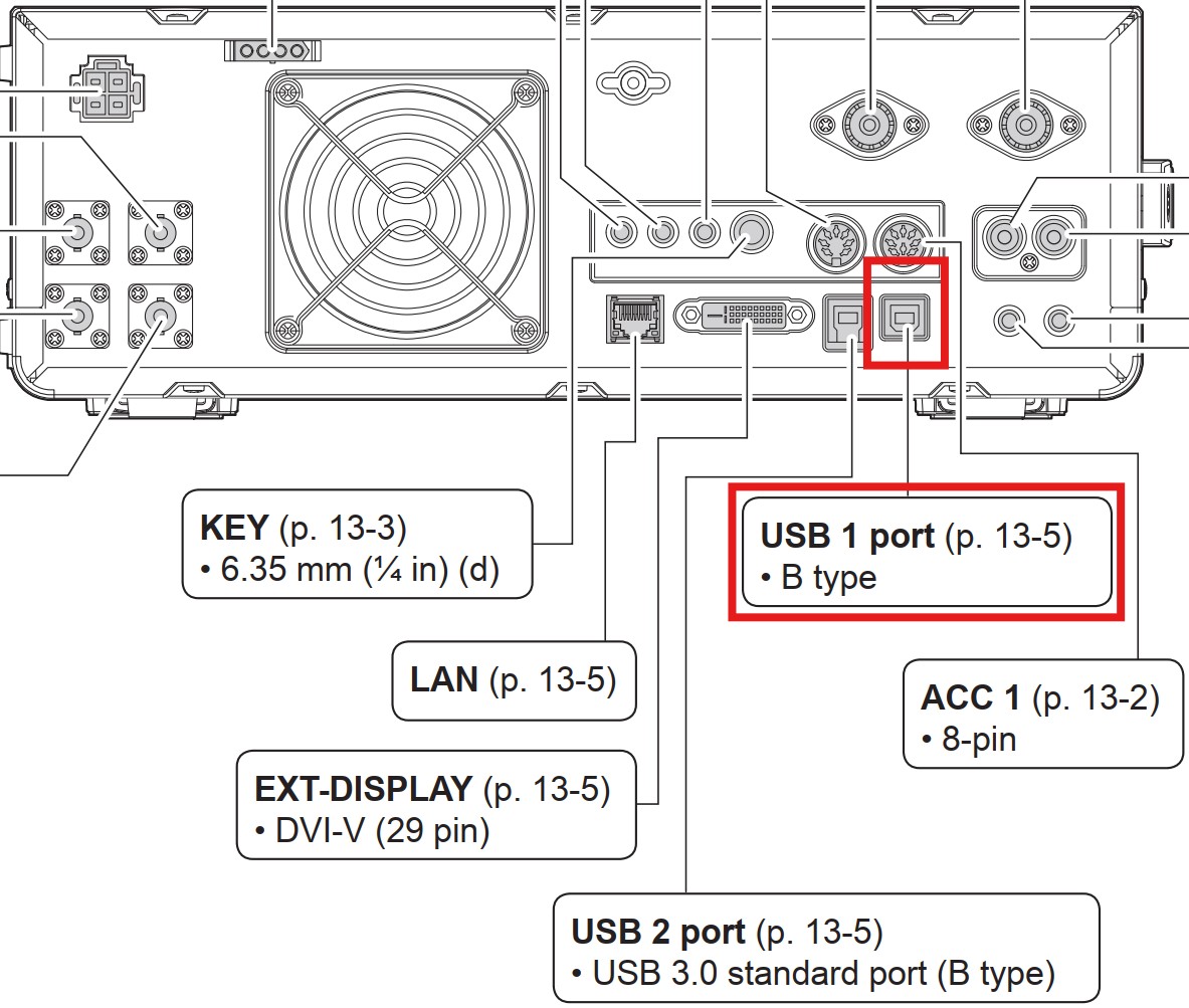
Starting at the Icom IC-7610 end I am using a single USB cable for everything. This is using USB port 1 on the IC-7610:

When active that gives me these two COM ports:
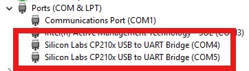
Yours will be different most likely but I think if yours were say COM2 and COM3 then wherever I use COM4 you would use COM2, and same for my COM5 v your COM3.
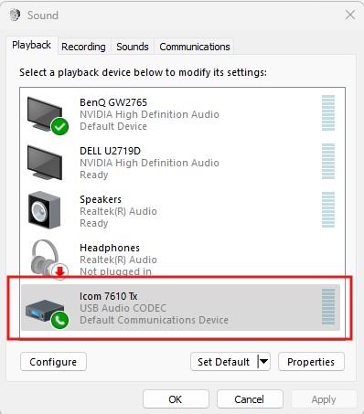
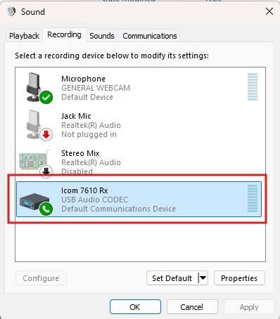
In Windows Control Panel/Sound, I have renamed the default device names for the IC-7610 to something sensible that I can recognise:
I had my first success (after walking away to calm down more than once!) using the radio’s RTTY mode which is FSK keying. I have since managed to get AFSK working but I don’t use that on the IC-7610.
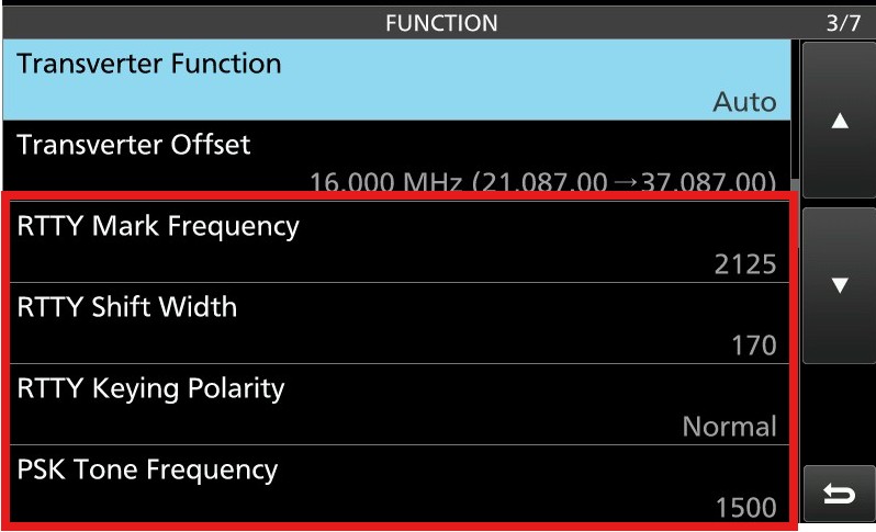
And these settings for RTTY are important (certainly the first 3, I haven’t touched the bottom one). Yours will probably already be set the same by default:
This setting I believe enables CAT to work on the first of the two COM ports the IC-7610 creates and RTTY to use the the 2nd COM port the IC-7610 works. It’s certainly how my radio is set and I have CAT control and RTTY working!

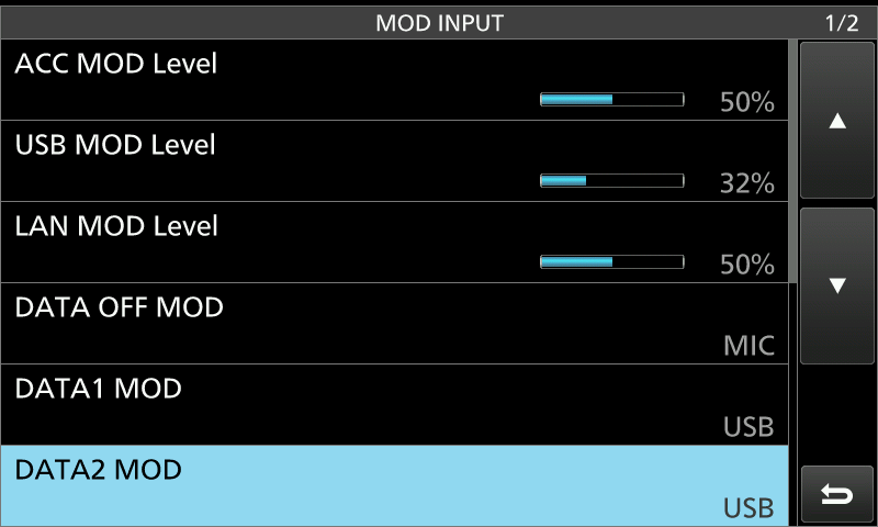
The following settings I didn’t cover in my own document to make RTTY work as I had already made some settings previous;y getting FT8 and CW etc working via the PC. So these may or may not have any effect:
PC end – DXLog & MMTTY.
Again, I am not claiming to be an expert on the IC-7610 or its settings, but these are taken from my working well setup.
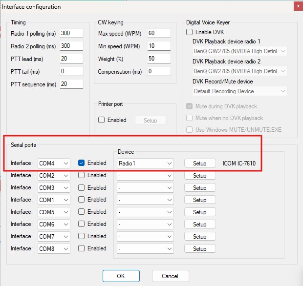
Firstly, this shows the single radio entry in DXlog configuration using the first COM port my IC-7610 creates, COM4:
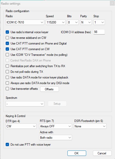
And the settings from clicking the Setup button on screen above:
The MMTTY version I use is the engine version downloaded from here:
https://hamsoft.ca/pages/mmtty.php
and the Engine only version because I am running inside DXlog:

This is UNZIPped into a folder on C: drive. No installer, just UNZIP. You can see that I have actually 4 folders. You can unzip the engine into multiple folders and when you choose that folder from DXlog and settings made are saved ONLY inside that folder. You can see I made 2 extra folders when I was getting AFSK working. That way my working MMTTY1 and MMTTY2 didn’t get broken!
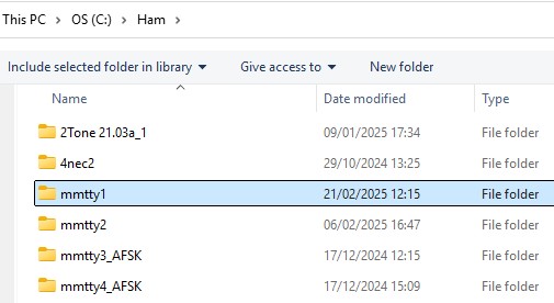 I have two FSK folders and two AFSK folder because I tried to get dual rx/tx going so I could run on TRX1 and S&P on TRX2 but I couldn’t tx on TRX2 so I just use the one RX now, but I have left the folders there in case. You will also notice I have a 2Tone folder there, which I use as my 2nd decoder on RX1. I won’t cover setting that up, but it went quite well and is highly recommended.
To use FSK you need to add a small program (actually a DLL) called ExtFSK into each of the MMTTY folders for FSK to work. You will find the ZIP file download right at the bottom of this page:
https://hamsoft.ca/pages/mmtty/ext-fsk.php
Just UNZIP the files into your MMTTY folder above.
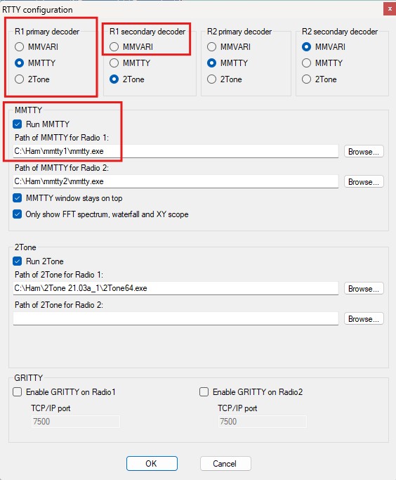
In DXLog RTTY settings I have these settings made. I have highlighted the settings for getting going with just one MMTTY instance for TRX on RTTY. For 2nd decoder if you leave as default MMVARI (I don’t have that that I know of) I see only the one decoder for MMTTY:
With the settings above made and opening an RTTY contest in DXlog you should see an MMTTY window like below appear. If not, in DXlog go to Windows/Digital Modes and tick next to MMTTY Radio 1:
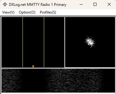 Mine looks like the above as I ticked in the settings window “Only show FFT spectrum, waterfall and XY scope”. I did this to save space. I never touch the settings that are visible other wise so decided I didn’t need them.
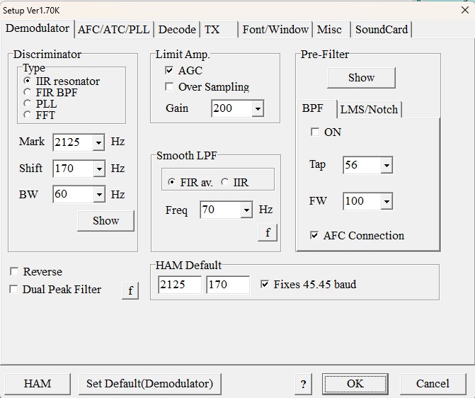
So on the window above click Option(O) then Setup. This takes you to all the settings on 7 tabs. These are my settings and may not be perfect but I am making QSOs!
Demodulator tab:
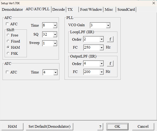
AFC/ATC/PLL Tab:
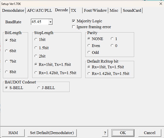
Decode Tab:
On this next tab TX, you need to select EXTFSK as shown from near the bottom of the list of possible COM ports:

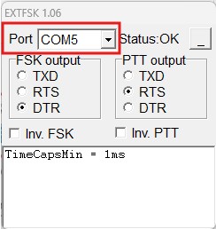
When you select EXTFSK as above, you should see a small window appear to make some settings. Here you can see I have selected the 2nd COM port COM5 that my IC-7610 creates. Also check the FSK output and PTT output as if you have set yours identical to mine they probably need to match up:
Font/Window tab:

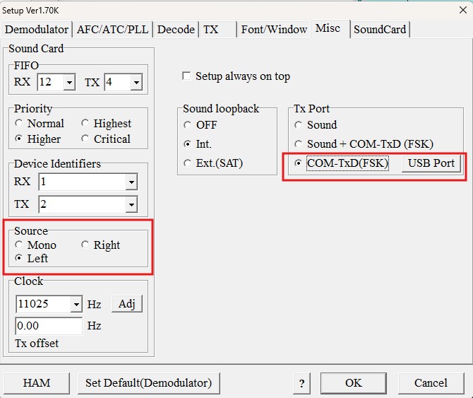
On the Misc tab need to set as highlights for COM-TxD(FSK). For source you can probably leave as Mono. I have told my windows to make the sound card for the radio to stereo for dual rx. For single rx default and mono should be fine:
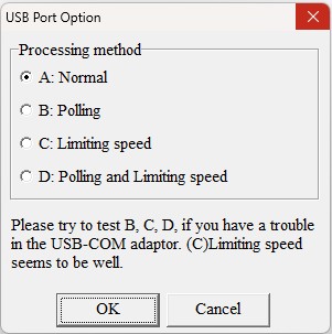
Clicking the USB Port button above looks like this:
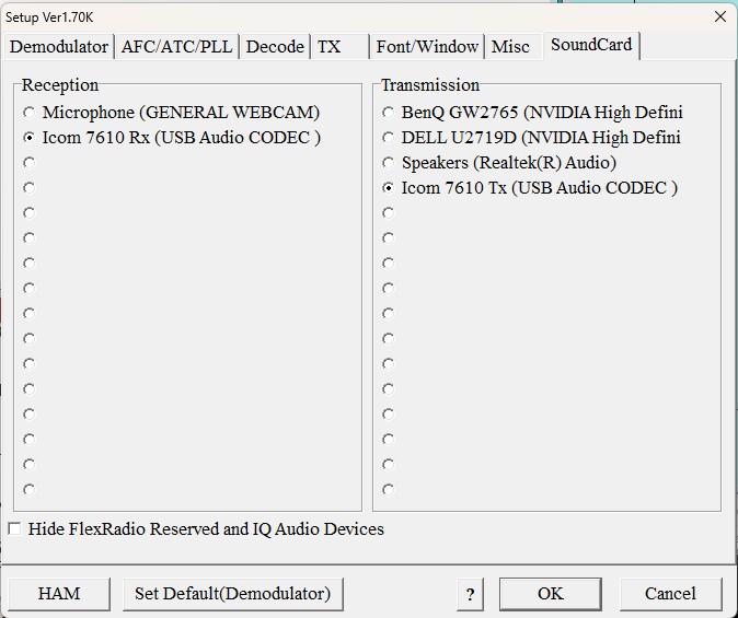
And the final settings tab, Soundcard:
One final setting that I was told to do when I was struggling to make it work is to right click in the decode window and tick the 2125 setting as shown. I’m not sure if that is essential now but I still have it set like that!

This is the end of the settings.
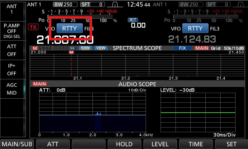
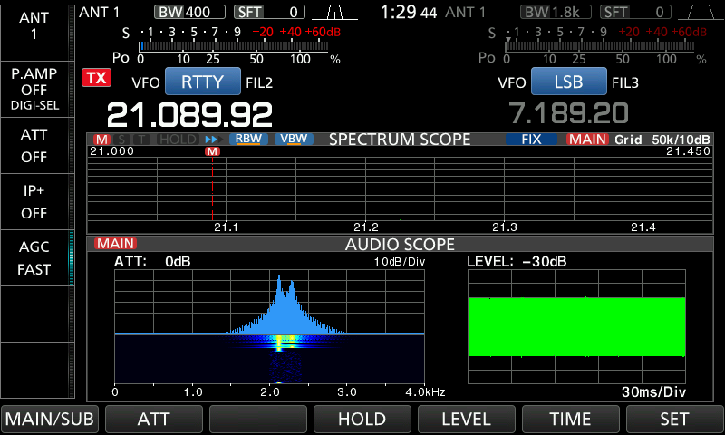
If you tx now from DXlog either via macro key or via ALT K and the free type window you should see something like this twin peak signal on your radio and hear the two tones going:
If you can find an RTTY signal on air you can use the inbuilt decoder in the IC-7610 to decode it and check MMTTY is decoding something the same!
You will see garbage like in my image above the last one. That is what MMTTY has decoded with no antenna connected to me IC-7610.
I hope this helps get more people going on RTTY as I for one found it VERY hard!
Last updated 21st February, 2025