I don’t actually collect QSL cards myself but I know people do so I do QSL via the bureau. The final courtesy etc so for many amateurs, QSL matters. NOT to Royal Mail it would appear.
Recently I had an email from my RSGB QSL sub manager telling me he was ending out my last two envelopes very soon. A couple of days later I received my ‘3 of 4’ envelope on its own. I assumed that ‘4 of 4’ hadn’t been sent but after waiting a couple more days I did check back with the sub manager and both were posted at the exact same time. Hmmm.
I’ve already previously had a completely empty torn bureau envelope delivered, thanks a bunch Royal Mail so I was expecting I’d never see that shipment of QSL cards and more amateurs around the world would think I was a git and not replying.

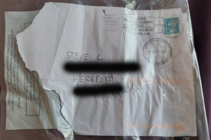
But a couple of weeks later through the door came saying “there is a fee to pay” of £1.50 for something giving the reason:
THE SENDER DID NOT PALL THE FULL POSTAGE
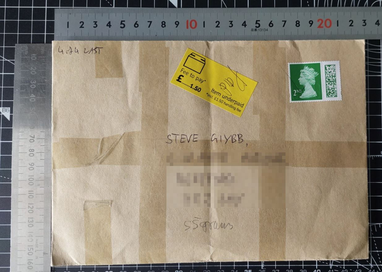
No clue to what it was but I had my suspicions. I paid the fee online then in a day or so sure enough through the door popped envelope ‘4 of 4’.
The very first thing I noticed was that the fee, supposedly for underpaid postage consisted of 100% handling fee.

So I got onto google to double check the sizes and weights for a normal letter which are:

And then double checked the letter even though I knew it would be fine. But I like to sure of my facts.

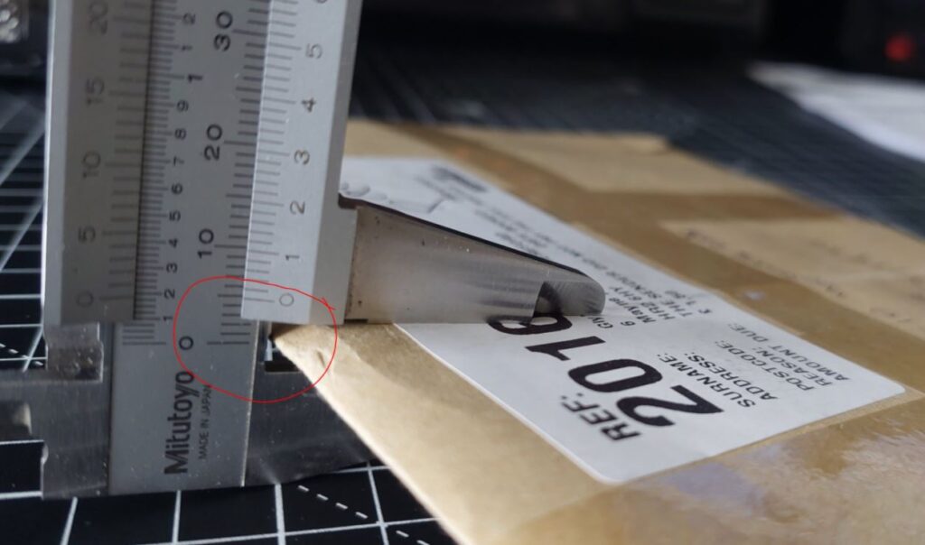

Clearly there is absolutely NOTHING wrong with this letter!
I decided I was going to take every step possible to recover what I consider extorted money. Might be only £1.50 but it might be £1.50 from 100s of 1000s of people, basically mass theft. I shared my annoyance on Facebook and was immediately directed to a group solely for people to advise each other on these matters so it is widespread.
Firstly I went down to my local sorting office wehre presumably my letter had lain for 2 weeks or so. They literally did not give a toss. Not the slightest. Just told me to pick up a card and ring that number.
Now we all know these customer service lines are deliberately undermanned in the hope that we will just give up. But I was on a mission now and sat at the computer working with the phone on speaker and let it work me down the enormous queue. Once through I did speak to a guy who said he would raise an issue but it didn’t sound very promising at all, I had the feeling I was being fobbed off.
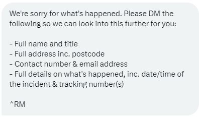
So I decided to speak up on Twitter. I find Twitter very good because all posts are public and you can tag them in a post which then appears on their feed and they can’t delete it and as a result most will direct message you to try to shut you up. Sure enough in a day or so I received the following DM:
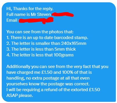
 To which I replied with the 3 photographs above (unpixellated of course) and this accompanying text:
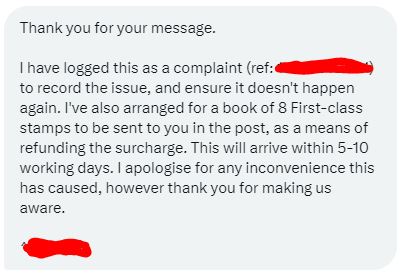
 Then 4 days later I got another reply:
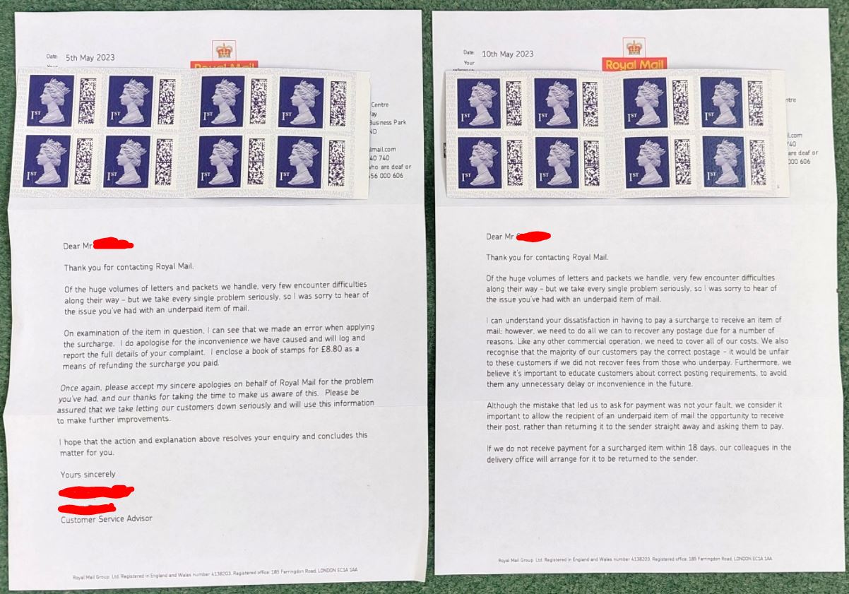
 By this time I was about to leave for a 10 day holiday so I had to wait until my return to see if I would actually receive the promised book of stamps. I noticed two matching envelopes in the mail pile and was surprised to see this:
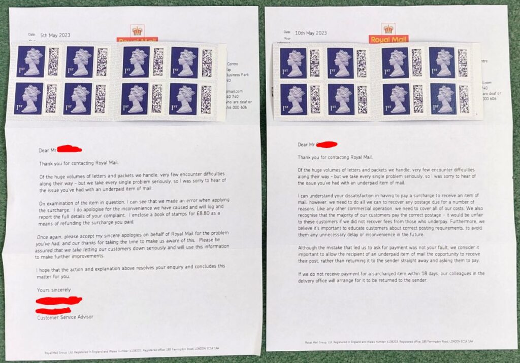
So I am guessing that both the phone call and the Twitter chat resulted in one of each letters. Clearly there is no coherency within the company as both were unaware of each other dealing with my complaints by the look of it.
So my moral of this long winded story is:
DON’T LET THEM GET AWAY WITH RIPPING YOU OFF.
Last updated 17th July, 2024