At my location it’s very difficult to have any sign of HF antennas (or any antennas for that matter) up in the garden. I’m already using a covertly erected dipole after dark using this quick erect fishing pole mount. But I was very interested in an ATU free multiband antenna. The hexbeam is nice but too big and needing a rotator. So I looked at the G3TPW Cobwebb antenna. For those unaware this is a 5 band dipole based antenna horizontally polarised and roughly omnidirectional working on 10, 12, 15, 17 and 20m. The folded dipole style with shorting points seemed more complicated than I fancied so I looked at the simpler G3TXQ cobweb design. This filled more boxes for me, single wires nice and easy to tune and a tidy looking feed box. However, it would still stand out in the garden due to it being some strange looking (to non hams) spoked wire thing. What I decided to try was up sweeping the spreaders to make my G1YBB Disguised ultralight Cobweb antenna look like a rotary washing line as there is already one in my garden. I was counting on the neighbours not noticing it had grown an extra arm and got a bit bigger. Except when actually in use I would keep it low down like a normal washing line such as this:
 continue reading
Author: Steve G1YBB
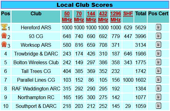
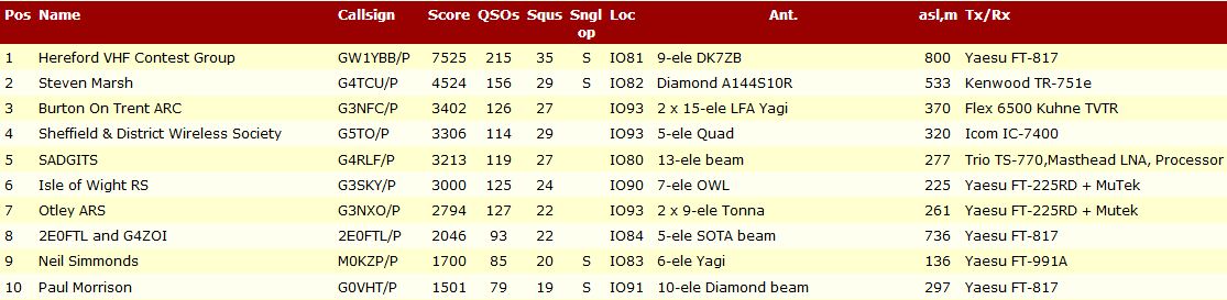
RSGB 50MHz Trophy contest June 2020
Earlier this week I built a simple wire moxon antenna for 50MHz for use at home, detailed on this page (link). The impetus for this build was to contribute towards the Hereford ARS campaign to retain the RSGB VHF Championship Trophy that we won over the year long 2019 contesting calendar.
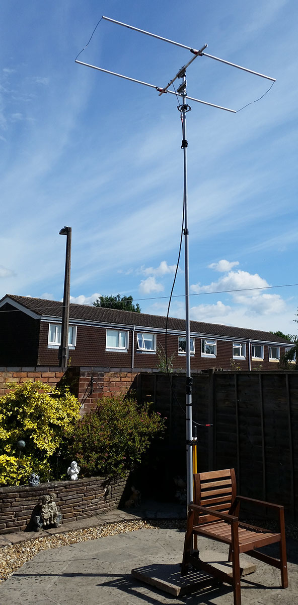
I already have a 50MHz yagi (link) for use portable when contesting but at 7.2m long it’s just too large to assemble in the garden and if I could get it to the height required for a clear view would put the fear of (deity) into the whole estate! So the plan is to add a few club points using the little moxon.
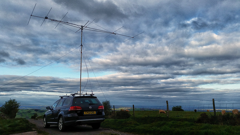
As you can see a vast difference in antennas! However I was not completely dismayed. I have been out contesting on the hills often with the big yagi and really struggled to break pileups to DX on sporadic E openings, usually with many other club members who I usually do better than just calling over the top of me. I’m always low power at 10W, but look at that beam man! So I have come to the conclusion that the vertical pattern of the long yagi is just not suited to the angle required to get good results on Es. I may be wrong as many others use reasonable beams but my post summer 50MHz contest catchphrase is:
“I bloody hate Es season!”
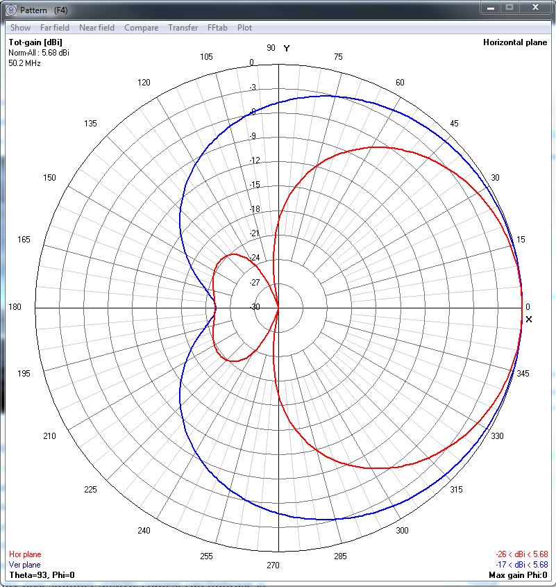
But the radiation plots of the moxon design I thought were very promising. Not only a great big fat front azimuth lobe (in red on graph below) with a 3dB beam width of 78° but a huge vertical shape )in blue on the graph) to it covering all take off angles you could imagine for Es. So despite having way under half the gain of ‘the beast’ that disparity in gain once we get off the main heading the moxon would ‘catch up’ a little and should also be launching skywards when required. My theory anyway!
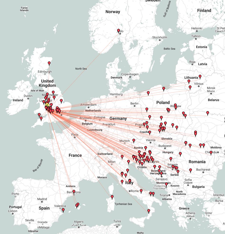
So, contest day. I planned to do just 6 hours and as it’s more family friendly to get that over with in one session for me so I opted for Sunday morning and the last 6 hours before the contest ended. Amazingly for me I seemed to have pretty much cherry picked the best slot of the 24 hours. I was 4 hours into the contest before I got any other G squares than my own and IO81 adjacent to my square (I sit on the join line at IO82PA). But I was busy with the Es! Great fun. I only have 100W max on 6m and whilst some of the pile-ups especially to EA were hard to break it was very enjoyable! One station ( I think Italian) even commented “wow such a huge signal” after our QSO. This is on two bits of wire and some plumbing tube!
I was completely unable to raise all the ‘local’ EU countries like F, ON, PA nor could I get any GD, GI, EI, GU, GJ. If I had their country and square mults would have upped my score nicely. However my new temporary summer 50MHz contest catchphrase is:
“I bloody love Es season!”
QSO map below:
Easy building of a moxon antenna with 4NEC2
As we are still on lockdown and my 50MHz yagi is literally too huge to fit in the garden let alone erect on my lockdown lash-up system I decided I needed to make something smaller to use at home. I didn’t have any aluminium tubing at home long enough to make a small yagi so I decided to make a moxon antenna on the recommendation of a friend. These are very compact and easy to make so it seemed like a plan. I decided on a wire based version as although I have some 12mm tube I could cobble together I didn’t have anything I could get today for the corners. Wire it is. I decided easy building of a moxon antenna with 4NEC2 simulations to find the correct starting point would be a cool project.
I’d already looked around the web and compared the various online moxon calculators and the AC6LA Moxgen program (link) and the Moxgen program seemed to be the best fit for the suggested spreader angles. (Even though I’m not using spreaders as such.) It’s dead easy, just put your desired frequency in and the wire size and click calculate:
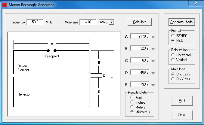
That’s it, job done. Almost… continue reading
Lockdown lash-up mast base
The coronavirus outbreak of 2020 put a stop to all portable radio activities so like many people I was forced to adapt and overcome and set up something at home. For non rotating mast systems I strapped a mast to the YL’s parasol base:
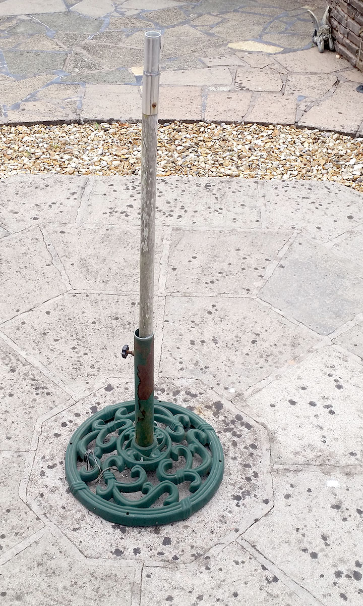
This worked for smaller dipoles but I wanted something a bit sturdier and the YL wanted her umbrella back! So I decided to make a new one. I thought about making something from scratch but after asking the local club members for ideas it was suggested to use a tamper that builders would bash sand down before laying slabs or bricks. A quick Google located one in stock in the local Toolstation: continue reading
70cms RG179 & RG302 DK7ZB match cutting jig
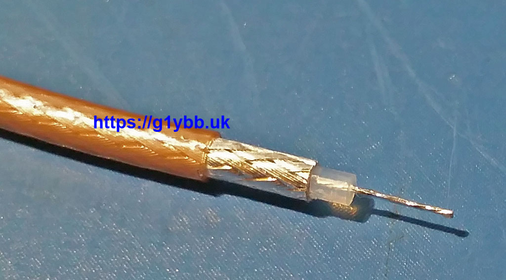
This DK7ZB match cutting jig will enable you to cut RG179 75ohm PTFE coax accurately and repeatably to the length required to make DK7ZB 28ohm matches. RG179 is chosen as it is easy to work with and is best used for antennas that will only be used as part of an array, or lower power use only. It should be good for about 300W PEP on 432MHz. This jig arrangement gives you enough braid to solder to with a very short length of exposed PTFE dielectric. At 432MHz you want to be keeping your ‘tails’ short and tidy for best results.
Design goal:
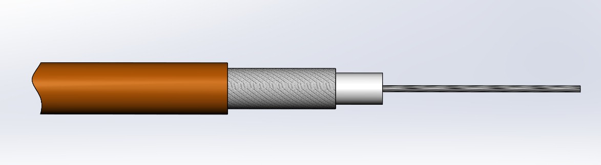
Reality:
Building the jig. continue reading
Icom IC-9700 Contesting review
This is my brief Icom IC-9700 Contesting review based on my experiences in many RSGB and other contests, nearly all portable on a hill top and all three bands the IC-9700 covers.
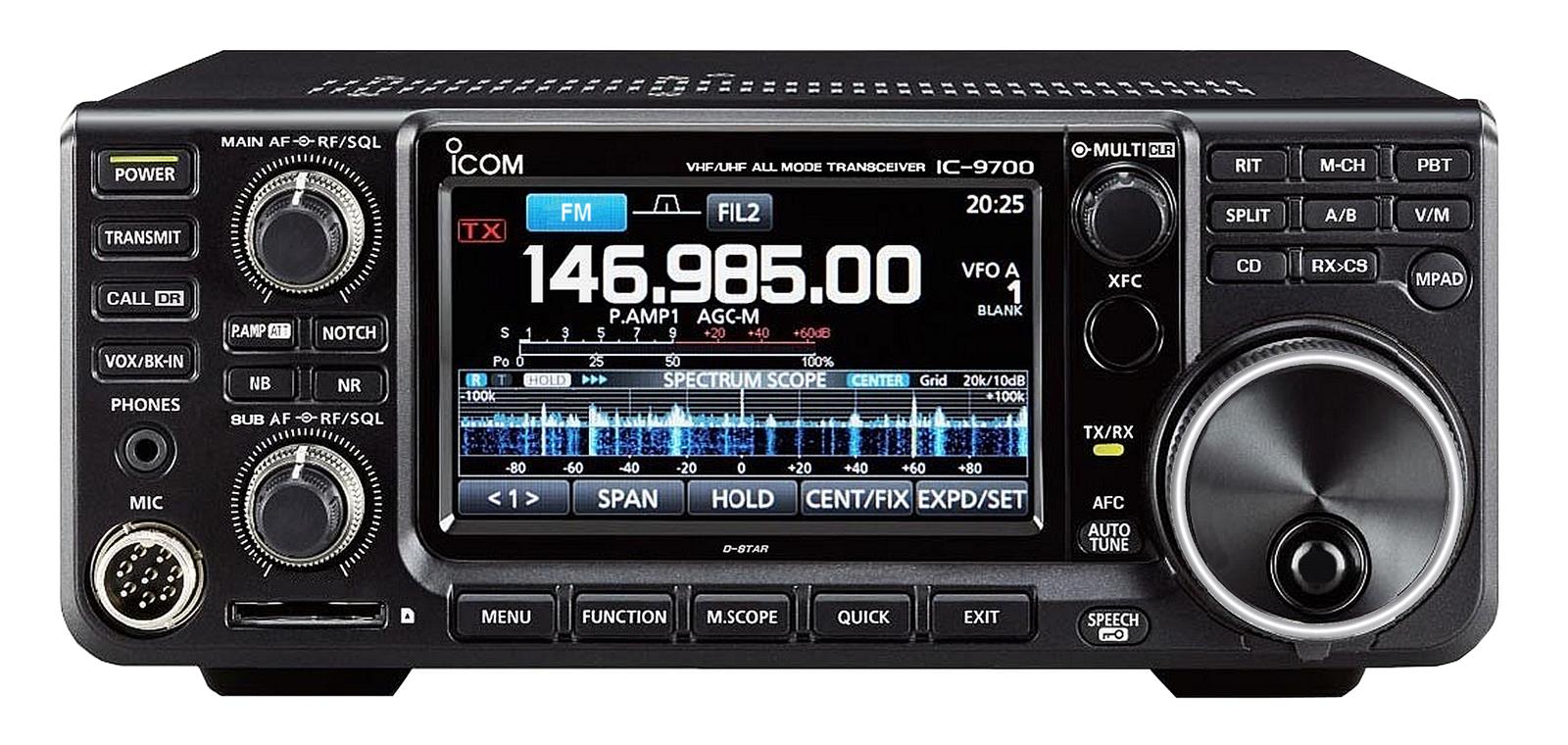
I bought the Icom IC-9700 at the time the second batch of this radio to hit the UK were being hotly sought after. I had recently got the IC-7300 before it, which I also love, so I was pretty keen to get this one to add to my portable contesting stable. In it’s early days there was a LOT of negative talk about dynamic range and frequency drift, I’ll touch on that at the end.
I can honestly say right now, I love this radio! Review done.
Oh you want to know why? OK headline points for me…
Functionality.
The IC-9700 has brilliant functionality for VHF contesting. The spectrum display is the biggest new thing to me (on 144MHz and up). Whilst this is brilliant for spotting signals on the band (and for this reason I think everyone ELSE should have one to find me!) not only that it has made the biggest gain to my 144MHz performance since getting the 9700. The way it actually did this, apart from the signal spotting ability, is to highlight why I was getting so much QRM on 144MHz. I always blamed other club members out portable nearby, line of sight, and some using FT-991 radios. Whilst they did batter me there were some nights I couldn’t find who it was killing me on the old school radio I was using. The 9700 soon showed me:
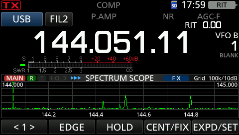
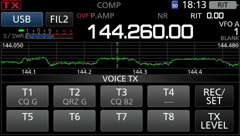 I was getting awful QRM and the OVF warning in regular all night long pulses, as you can see all over the band, but particularly hammering me where I usually run (144.265). That’s no ham! We determined the source to be a local (100 metres away) pager system. For so long I had suffered this QRM without realising the true source. It took me a while but after buying one filter that wasn’t sharp enough I borrowed another bandpass filter that took out this pager QRM and left me with a bandscope a little healthier looking!
 Couple this with the excellent receiver the 9700 has and it has truly transformed my 144MHz operating, and also on the other bands based on the receiver.
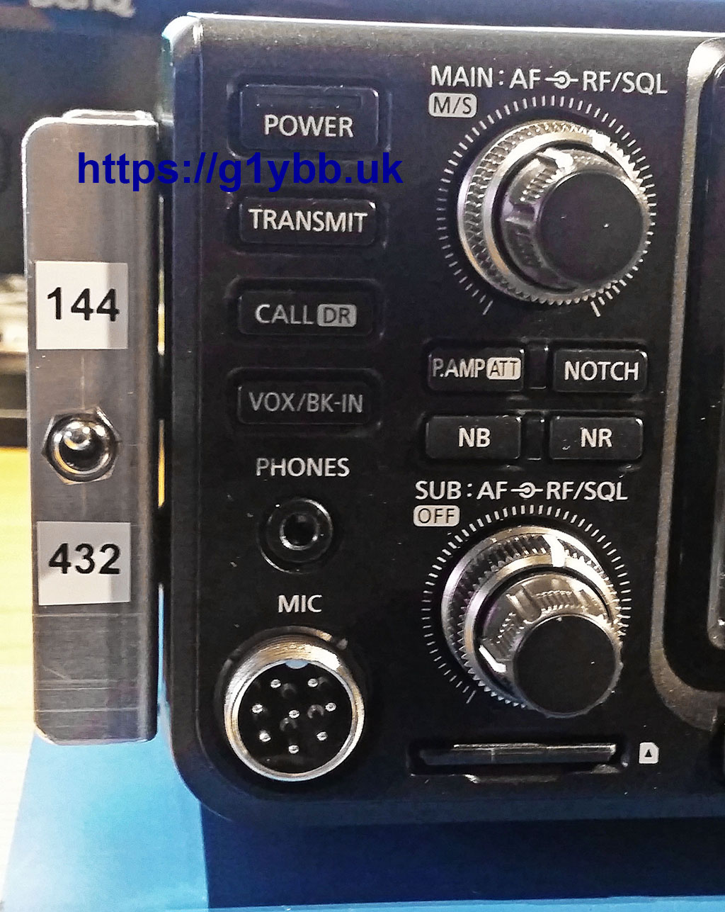
In the first QRM image above you can see I have the inbuilt memory buttons showing. The IC-9700 has these for voice and CW (maybe data?) and these are a complete godsend. I use two for contesting and one for general calls pre-contest. They auto repeat and you can get an external box to replicate the first 4 buttons. (Another build in the future)
You can connect the 9700 to your PC with a simple USB cable and get CAT control and data in out for things like digital modes, computer reading and sending of CW etc. So much easier than buying a rig interface box. I just use CAT when I am contesting.
The 9700 will also record both sides of a QSO as you go onto the SD card. Useful for DXers and the RSGB recommend doing this for contests. I guess it would be good for resolving disputes.
Those are probably the biggest plus points for me that I use all the time. Receiver functionality like adjustable filters and notch filters etc are there but not unique to this radio of course.
Performance.
As I touched on above, the radio performs excellently in my opinion. It won’t match a top HF rig into a high spec transverter of course, and may not have the optional roofing filters some radios have, but I have done very well with mine and I have seen quite an improvement in my scores since getting this and the 7300 (which I also love and has basically the same features). I find the receiver excellent and pretty good at withstanding some strong QRM locally as we have a pretty good turnout in the UKACs at Hereford ARS.
This radio does satellites (I know nothing about that) and can receive on two bands, but one of the first things I did when I got it out of the box was turn off the sub-receiver never to be used since. Until this March! March sees the RSGB March 144/432MHz where you need to operate on both bands at the same time. Not possible simultaneously as a single op but I set up with two antennas and two amps and ran on 144MHz and 432MHz, using CAT control from Minos to change bands by changing logs. Worked so well. However one thing I didn’t realise it could do was receive on one band while transmitting on the other. In the video below the 9700 is sat on top of the 70cms amp that you hear click when I Tx
I’m pretty impressed by that (as you can tell).
The “Bad Things”
When the IC-9700 was first announced there was a lot of talk about insufficient dynamic range to handle huge signals whilst receiving weak ones. Now whilst this might show up in a contest like 144MHz Trophy (IARU Region 1 in rest of EU) with huge signals from multiple antenna arrays and QRO amps (in fact our club station had such a complaint from a fairly close line of sight 9700 user) I can say that I have never had this that I can recall from another radio amateur. The only time my 9700 has shown OVF (overflow) is from the local pager mentioned above and from the Clee Hill radar station on 1296MHz. Bear in mind that I operate 11km away from G4ASR who has been known for being a very strong signal for many, many, many decades. (hehe Dave). I get strong signal QRM from him if too close in frequency when pointed at each other, but he has never put the 9700 into OVF (That is NOT a challenge Dave)
When the first units were received there was a lot of talk about temperature based frequency drift. It was the end of the world as we know it. Icom has since come up with a firmware upgrade to assist and GPS locked board and mods are available. I feel it’s worth mentioning I am using one of the very early units and it is as it came out of the box. No firmware updates have been applied. None have had anything I felt I needed. I don’t do data modes (to date) just primarily SSB. I have never had anything mentioned to me about drifting and never noticed anything on receive. That’s on all 3 bands. I do only normally use the radio on 10W on each band so I probably generate less of a temperature change. (They say it multiplies up on 1296MHz)
So if you want to actually talk to people yourself rather than letting a computer do it for you, the 9700 works. Works well.
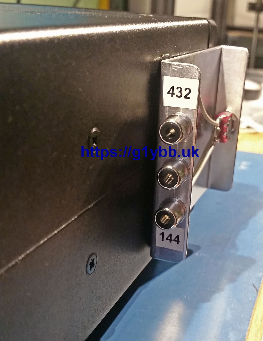
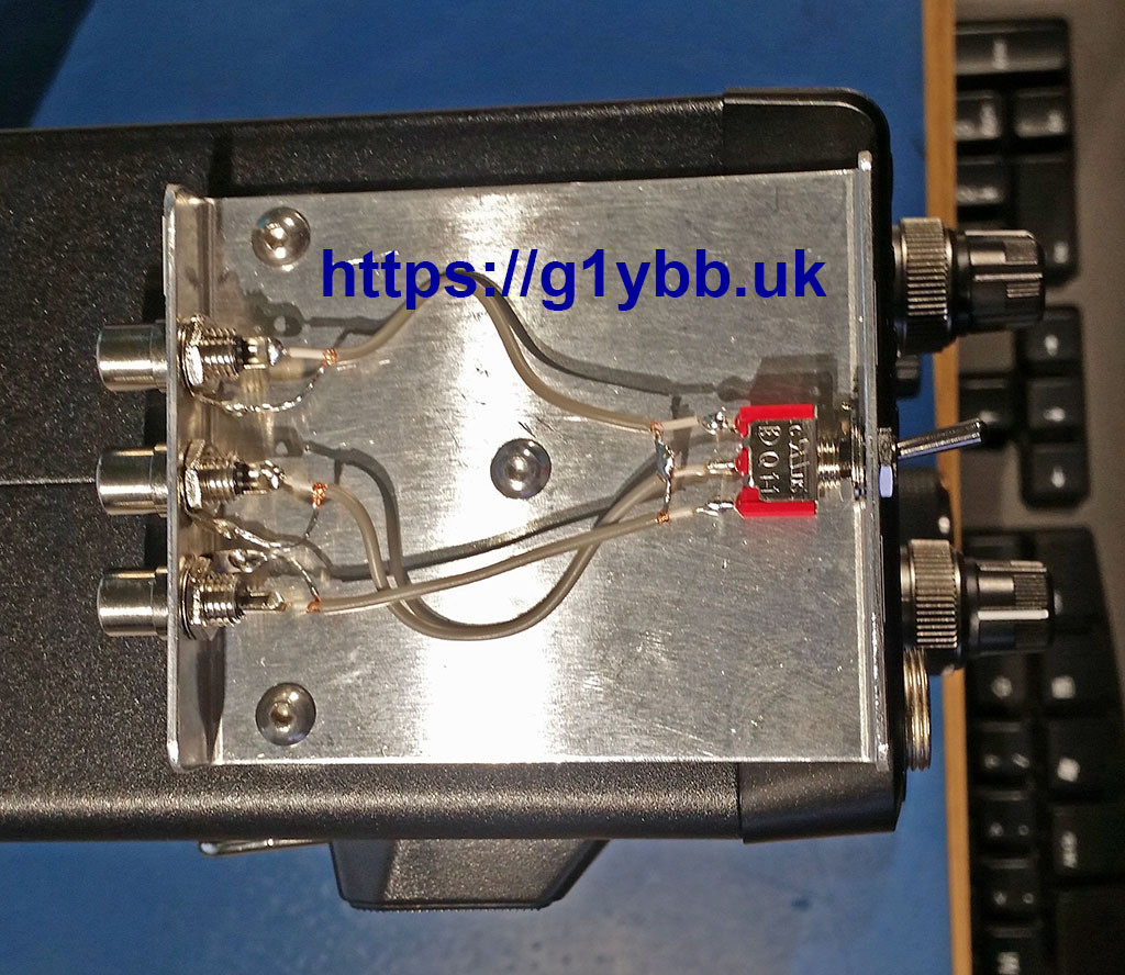
One real issue that has reared its head with me is the single PTT output for driving amps and transverters etc. There is only one contact available that grounds on Tx for all three bands. People have designed units that read the C-IV data and generate a band specific PTT output and I do plan to build one of these myself. For a recent dual band contest however I did something a little more old school:
Summary.
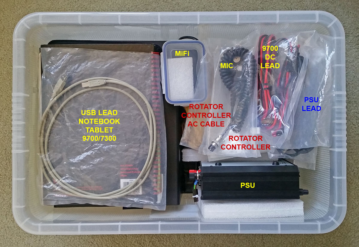
I am really happy with the purchase of the IC-9700 to accompany the also great IC-7300. One thing I like is the matching form factor. They are practically identical so I can alternate them in my portable box depending on the band I’m using.
My suggestion is to think carefully about what the naysayers are actually saying and decide if their nays will actually have anything to do with what you want to do with the radio. For example, I’m not currently interested in EME or data modes like FT8 so the drift ‘problem’ doesn’t bother me. If I decide to do data, then there are firmware and hardware solutions ready to solve that.
Did I mention I love my Icom IC-9700?
G1YBB Contest Results 2019
List of G1YBB Contest Results 2019 I have participated in. Where I have had chance to post a report there is a link to that post.
Individual Events
RSGB 144MHz UKAC January 2019
RSGB 432MHz UKAC January 2019
RSGB 50MHz UKAC January 2019
RSGB 1296MHz UKAC January 2019
RSGB 70MHz UKAC January 2019
RSGB 2.3GHz UKAC January 2019
RSGB 10GHz UKAC January 2019
RSGB 144MHz UKAC February 2019
RSGB 432MHz UKAC February 2019
RSGB 50MHz UKAC February 2019
RSGB 1296MHz UKAC February 2019
RSGB 70MHz UKAC February 2019
RSGB 10GHz UKAC February 2019
RSGB March 144/432 (144MHz) 2019
RSGB 144MHz UKAC March 2019
RSGB 432MHz UKAC March 2019
RSGB 50MHz UKAC March 2019
RSGB 1296MHz UKAC March 2019
RSGB 70MHz UKAC March 2019
RSGB 2.3GHz UKAC March 2019
RSGB 10GHz UKAC March 2019
RSGB 144MHz UKAC April 2019
RSGB 432MHz UKAC April 2019
RSGB 50MHz UKAC April 2019
RSGB 1296MHz UKAC April 2019
RSGB 144MHz UKAC May 2019
RSGB 50MHz UKAC May 2019
RSGB 432MHz UKAC May 2019
RSGB 70MHz UKAC May 2019
RSGB 2.3GHz UKAC May 2019
RSGB 144MHz 1st Backpackers
RSGB 144MHz UKAC June 2019
RSGB 144MHz 2nd Backpackers
Practical Wireless 144MHz QRP 2019
RSGB 432MHz UKAC June 2019
RSGB 50MHz UKAC June 2019
RSGB 1296MHz UKAC June 2019
RSGB 70MHz UKAC June 2019
RSGB 2.3GHz UKAC June 2019
RSGB 10GHz UKAC June 2019
RSGB 144MHz UKAC July 2019
RSGB 144MHz 3rd Backpackers
RSGB 432MHz UKAC July 2019
RSGB 50MHz UKAC July 2019
RSGB 1296MHz UKAC July 2019
RSGB 70MHz UKAC July 2019
RSGB 144MHz Low Power
RSGB 432MHz Low Power
RSGB 50MHz UKAC August 2019
RSGB 432MHz UKAC August 2019
RSGB 70MHz UKAC August 2019
RSGB 1296MHz UKAC August 2019
RSGB 144MHz UKAC September 2019
RSGB 50MHz UKAC September 2019
RSGB 1296MHz UKAC September 2019
RSGB 70MHz UKAC September 2019
Practical Wireless 70MHz 2019
RSGB 2.3GHz UKAC September 2019
RSGB 144MHz UKAC October 2019
RSGB 432MHz UKAC October 2019
RSGB 1296MHz UKAC October 2019
RSGB 70MHz UKAC October 2019
RSGB 2.3GHz UKAC October 2019
RSGB 10GHz UKAC October 2019
RRSGB 144MHz UKAC November 2019
RSGB 432MHz UKAC November 2019
RSGB 1296MHz UKAC November 2019
RSGB 144MHz UKAC December 2019
RSGB 432MHz UKAC December 2019
RSGB 50MHz UKAC December 2019
RSGB 1296MHz UKAC December 2019
—————————————-
sec
AL
AL
AL
AL
AL
AR
AR
AL
AL
AL
AL
AL
AR
6O
AL
AL
AL
AL
AL
AR
AR
AL
AL
AL
AL
AL
AL
AL
AL
AR
5B
AL
5B
NA
AL
AL
AL
AL
AR
AR
AL
5B
AL
AL
AL
AL
MO
MO
AL
AL
AL
AL
AL
AL
AL
AL
LP
AR
AL
AL
AL
AL
AR
AR
AL
AL
AL
AL
AL
AL
AL
—
AL
AL
AL
AL
AL
AR
AR
AL
AL
AL
AL
AL
AR
6O
AL
AL
AL
AL
AL
AR
AR
AL
AL
AL
AL
AL
AL
AL
AL
AR
5B
AL
5B
NA
AL
AL
AL
AL
AR
AR
AL
5B
AL
AL
AL
AL
MO
MO
AL
AL
AL
AL
AL
AL
AL
AL
LP
AR
AL
AL
AL
AL
AR
AR
AL
AL
AL
AL
AL
AL
AL
—
res
1st
1st
1st
2nd
1st
9th
5th
1st
1st
1st
3rd
1st
6th
2nd
1st
1st
1st
2nd
1st
6th
4th
1st
1st
1st
3rd
1st
1st
1st
1st
11
1st
1st
1st
1st
1st
1st
1st
1st
3rd
5th
1st
1st
1st
1st
1st
1st
1st
1st
1st
1st
1st
2nd
1st
1st
2nd
1st
1st
21
1st
1st
1st
1st
9th
12
1st
1st
2nd
1st
TBC
1st
2nd
—
1st
1st
1st
2nd
1st
9th
5th
1st
1st
1st
3rd
1st
6th
2nd
1st
1st
1st
2nd
1st
6th
4th
1st
1st
1st
3rd
1st
1st
1st
1st
11
1st
1st
1st
1st
1st
1st
1st
1st
3rd
5th
1st
1st
1st
1st
1st
1st
1st
1st
1st
1st
1st
2nd
1st
1st
2nd
1st
1st
21
1st
1st
1st
1st
9th
12
1st
1st
2nd
1st
TBC
1st
2nd
—
Series results
RSGB 144MHz Backpackers 2019
RSGB 144MHz UKAC 2019
RSGB 50MHz UKAC 2019
RSGB 432MHz UKAC 2019
RSGB 70MHz UKAC 2019
RSGB 1296MHz UKAC 2019
RSGB 2.3GHz UKAC 2019
RSGB 10GHz UKAC 2019
RSGB Overall UKAC 2019
RSGB 144MHz Backpackers 2019
RSGB 144MHz UKAC 2019
RSGB 50MHz UKAC 2019
RSGB 432MHz UKAC 2019
RSGB 70MHz UKAC 2019
RSGB 1296MHz UKAC 2019
RSGB 2.3GHz UKAC 2019
RSGB 10GHz UKAC 2019
RSGB Overall UKAC 2019
sec
5B
AL
AL
AL
AL
AL
AR
AR
NA
5B
AL
AL
AL
AL
AL
AR
AR
NA
res
1st
1st
1st
1st
1st
1st
20
12
3rd
1st
1st
1st
1st
1st
1st
20
12
3rd
Yaesu FTDX-5000 transport case
THIS IS NOT A FLIGHT/SHIPPING CASE!!
This is a FTDX-5000 transport case for things like taking it to field day etc.
As the FTDX-5000 is an expensive and heavy beast I designed and made a transportation/storage case to fit it. I’d looked at what you could buy and everything was huge and heavy, increasing the size of the 5000 by a considerable amount. Something simple, low profile and low weight was required.
Images are clickable for larger version.
Below is the resulting case. It’s powder coated aluminium, adorned with protective foam so the radio never gets scratched or dusty/wet (just care fitting the lid is all required) and has latches to quickly but securely lock the lid on. Once in the case it can be carried around without fear of accidental bumps, things falling on it, kids fiddling or rain (to and from car etc).

The box is designed to enable the radio to be operated whilst still in the base, and even offers a handy place to hang the standard microphone: continue reading
VHF Contesting hints, tips and guide
VHF Contesting hints, tips and guide for starting out in HF, VHF & UHF contesting and things for keeping your equipment in great shape. I’m no expert, but I have been VHF contesting since the 90s (with a break) and have made most of the mistakes one can, and won a decent share of contests too. So I thought I would pass on some of the things I feel are useful to do well in VHF and UHF contesting.
So, What do you do then?
In a nutshell nothing more than exchange some information with as many other contesters as possible over the duration of the contest. On VHF that is typically a signal report, a sequential number, one per QSO and your six figure QRA (Maidenhead) locator. Some also have postcodes or other information, stated in the rules. If you don’t know your QRA locator it’s easy to find from such sites as this one:
http://k7fry.com/grid/?qth=IO82PA&t=n
How do I do it?
There are two main ways to operate, running and search and pounce. Running is sitting on a frequency and calling CQ hoping people will come to you. New starters often prefer to search and pounce. This is just tuning around the band until you find people calling CQ Contest. You then ‘pounce’ on them, which is just calling them. A good tip is to listen for a while to see what information they are exchanging. Usually these running stations are looking for an efficient QSO so another tip is to note the QRA locator they are giving ready so you only have to log (more on that below) the signal report and their serial number (which you should also be able to plan as it will be one more than the previous QSO). Also, make sure your RIT is off or at zero and use the main tuning dial to tune the station in if on SSB, so when you call you are readable to the station
So, they might say:
“CQ Contest golf one yankee bravo bravo CQ contest”
or if finished a QSO with someone:
“thanks, QRZ golf one yankee bravo bravo”
just call with your callsign once:
“mike nine alpha bravo charlie”
The running station will then send you his report and information and be looking for yours.
Here is a sample QSO:
Notice the station G3SMT checked he heard my sent serial correctly, but otherwise did not repeat back to me what I said. I don’t need to know that, I sent it! He also sent his information clearly and concisely just the once. If I’m a good signal his end, and I have just said he’s 59 then likely as not I can hear him very well and get it all in one go. I could be suffering bad QRM in which case I will request repeats.
OK, sounds easy enough, let’s do it…
To get started there are several considerations to make but all are dependant on what you want from VHF contesting. Some people just enjoy “giving points away” which is calling people like G3SMT did above and not sending an entry in at all. You don’t have to. It can be a great way to work good distance on a modest home station as often the running stations have a good station in a good location and can hear you better than most stations. Or you might decide to go all out and try to win contests. Or maybe take part in club/team based contests and be part of a whole. The choice is yours. So these considerations then….
Location, location, location
Your location and/or take-off can have a massive effect on VHF/UHF. Obviously if you are a fixed station without moving house (and some people do!) you have what you have. Try to get the antennas clear of any obstructions of course. If you really have a poor VHF site at home then maybe look at portable. Even a modest hill can transform the performance of the same station set-up. With a good spot with good take-off you don’t need massive masts at all. On 144MHz I use just a 4m high mast but from a VERY good location and I do really well. At other locations I use a 6m mast and also do well.

Antenna
My ethos is big is beautiful! I want as long as possible on each band within reason. You want a decent gain and good performance, ideally an excellent match too. Pointless wasting permitted power by reflecting it back down the cable!
I’m a big fan of the DK7ZB designs and many of my antennas are home built to his designs.
http://www.qsl.net/dk7zb/start1.htm
Other designs are of course available and many places are selling commercial yagis made to modern computer optimised designs on the internet.
Radio
Most of us use the radio we have that covers the band. But if you can look for one that has a good dynamic range, that can deal with big signals and receive weak ones. It’s a big ask and most of the top stations use a high spec transverter with a top HF radio driver. However, the other other end of the coax in the picture above has a little Yaesu FT-817 at the end! Be sure not to overdrive whatever radio you use, other contest stations will not appreciate it and some stations I have worked are so turned up to number 11 I can barely make out what they say.
Logging
Computer logging, while not essential, makes things so much easier and faster. Instant dupe checking and aids like headings for the beam based on QRA locators. Also the ability to export the entry files easily. These days of tablet PCs you can take PC logging with you anywhere.
My favourite free option for VHF is Minos:
https://g1ybb.uk/entering-rsgb-vhf-contests-with-minos-logger/
Another free program that will do VHF and HF is N1MM+, though I will say it (for me) requires more setting up. But it is very powerful and will integrate with many other programs, like datamodes and CW readers etc.
https://n1mm.hamdocs.com/tiki-index.php
Finding the contests
The majority of the UK based VHF and up contests are run by the RSGB. The current calendar can be found here:
https://www.rsgbcc.org/cgi-bin/readcal.pl
One of my favourite contests is the Practical Wireless QRP contest. PW contest info is here:
http://www.pwcontest.org.uk/
Worked All Britain also run VHF contests, their calendar is here:
https://wab.intermip.net/Contest%20Dates.php
That’s it, you’re ready to go contesting. Have fun!
Hints and Tips.
Contesting is competitive by nature so once you have caught the bug the natural progression is you will want to do better. I believe attention to detail is paramount.
Use the best coax you can afford to get every drop of signal in and out. Don’t have loads of spare feeder length if you aren’t going to need it.
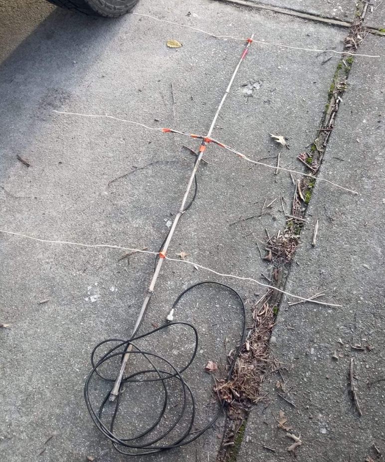
Keep your yagis in good shape. Whilst the yagi below will work, I cannot believe it will work as well as it would if all the elements were dead straight and all in line in all planes. The difference might be a fraction of a dB but every fraction improvement added together can make a difference.
I keep my RF connections clean. Of more importance to a portable operator than a fixed station maybe, but personally I don’t think dirt, grass, spiders and other rubbish are very good RF conductors. It may not make a difference, but it definitely will not do harm.
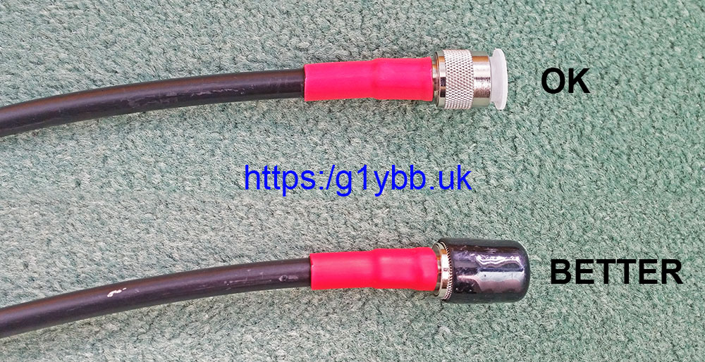
 I also use adhesive lined heatshrink on my feeder connectors to both waterproof them and stop movement between the coax and connector which leads to faults.
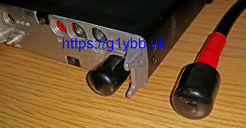
Edit: This week for May 2019 50MHz UKAC it had been raining during the day and the sheep are out in the field I use. I was coiling up the feeder to pack away in the dark and when the end came into view I could see it had managed to completely submerse itself in fresh sheep poo! The entire black rubber cap was covered in it. That would have all been in the threads and centre pin and made a right mess. As it was I just wiped off in the wet grass and dried it off with a tissue.
This backs up the above and also reminds me that the over the outside cap is best option:
Practice makes perfect.
Operating is one of the areas that can really make a difference. Different operators with the exact same equipment at the exact same spot can achieve vastly different results. Contests have fixed duration so speed is of the essence. More is good. Faster is good. But not at the expense of accuracy. Pointless making a dozen QSOs in a few minutes if they are all discounted due to errors. Do double check the difference between 55 or 59 which can sound the same.
Make a call on the exchange style based on the caller.EG, here is a strong station who is a known good operator:
No repeating of information is required either end. Both of us know the other will get it first time, and both stations know the other will appreciate expedience.
Another QSO example with a weaker more distant station, and also right in the last throes of a contest so with some urgency too! Repeats given my end to try to ensure QSO completes before the clock runs out.
Do use the technology available and permitted. ON4KST chat is permitted in many contests and is an extremely useful tool for attracting more QSOs. Not using it to be ‘old school’ is self imposing a handicap for no reason, in my opinion. I always use it if replies to my CQs are drying up. It is especially handy for seeking out new multipliers or bonus stations.
Later versions of Minos have features like memories where you can store the call and frequency of other run stations. Coupled with CAT control this can enable you to quickly and efficiently jump to other frequencies to work a new station and be back to your run frequency efficiently.
Use the other VFO if your radio has it. I have often called another run station, heard him take another caller, flipped back to my run freq, called, worked a station, and returned to the other station in time to hear him coming back to me. That’s an extra QSO for me. It needs practice and a feeling for how the other run station operates to not ‘miss your slot’ and be less efficient.
Look after the operator.
The operator wants to be fully focused on his/her game. They do not want to be battling with the weather, struggling with cold stiff fingers, or any other distractions. Ergo, apart from backpacking contests I always use a rotator, I have good lighting and if really cold, add heating. I don’t want to be opening windows into the cold and lashing rain or snow in order to turn my beam. I take a comfort break 5 minutes before the contest starts and usually do not move from the ‘hot seat’ until the contest ends, including backpacking 7 hour contests.
Never quit early! Very often even when it seems as if there is no one left to work you can work new stations and multipliers right at the end. It happens all the time. The last UKAC I did was hard work in the last half hour but in literally the last 2 minutes I worked 2 new French squares for 866 QSO points and 1000 bonus points with one of the QSOs being my ODX for the contest. That was 8% of my total score in the last 90 seconds or so! My last QSO was nearly 10 minutes before. I could easily have thought sod it and let’s go home.
Last word…
Enjoy it! If you do all the contests in the calendar it can seem like a full time job! Especially doing 6 UKAC events a month plus weekend contests. Add in HF and you have divorce grounds right there!
But whilst I like to take it seriously and do my very best to win, you can still have fun doing so. One QSO from a backpackers contest:
73 Steve G1YBB/P or GW1YBB/P normally.
G1YBB VHF Contest round up 2018
My G1YBB VHF Contest round up 2018.
For 2018 there was lots to do, both on a personal level and club level. personally I wanted to do well again in the Backpackers series, PW 144MHz QRP and the UKAC series. Busy busy busy! Club wise we ended 2017 with strong results so we wanted a good push in the local club section of the RSGB UKAC series.
144MHz PW QRP.
As ever this is the one I want to win more than any other as it was my first ever contest in 1990. This year Paul G1YFC couldn’t make it so I was single op. And single carry… The weather this year was fantastic, sunny, warm, and calm. The downside of that was by the time I reached the summit of my portable site in the Black Mountains I was practically done for! Sweltering and exhausted. But a short rest and back to business setting up the station.
This year I had made a new single piece 4m mast specifically for backpackers to not take any extra waste, but more importantly, enable me to set it up in high wind easier on my own. It took two of use 2 hours to erect my telescopic mast last year, so didn’t want to be trying that on my own. Luckily it was nice and easy with next to no breeze. In fact my biggest problems were heat and flies!
Activity was great with 85 QSOs in the first hour and over 200 QSOs in all, the highest since 2009. ODX was over 700km with DL6YBF who was really strong with me.
My efforts were rewarded with a 3rd successive win which I am dead chuffed with.
70MHz PW Contest.
As I now have 70MHz capability I thought I should have a bash at the PW 70MHz contest for the first time. This contest was a couple of days after the September 70MHz UKAC which saw the some serious wind and rain from storm Bronagh. The forecast for the Sunday was also pretty dire so I decided to operate from a lower spot below the summit which is more sheltered but loses me my clear 360° take off. This is OK for me in the RSGB UKAC as I get great PPK due to the great take off East and North but with PW only 1 point per QSO would be a bit of a restriction. As it turned out the forecast was pessimistic and it wasn’t a bad day after, but I’d already committed to not going to the top.
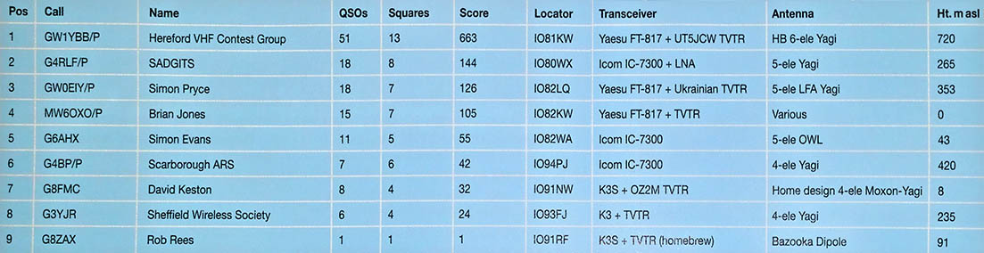
As it turned out I managed to roust up a good number of QSOs which is ‘my thing’ and also luckily a decent square count, enought to take my first ever win in the PW 70MHz Low power section.
RSGB 144MHz Backpackers.
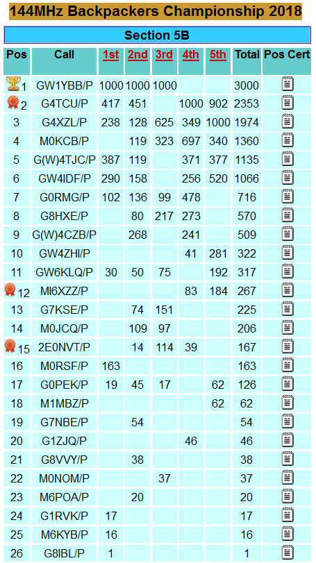
Loving the low power mountain top contests as I do I was keen to try and retain the backpackers Trophy for a 3rd year.This year Paul G1YFC couldn’t make any of the events so I was single op for all which meant being the armstrong rotator as well as logging and operating. However I managed to win the first 3 sessions which was enough to seal the win, which I needed to do as I had other plans for the last two sessions.
RSGB 70MHz Cumulatives.
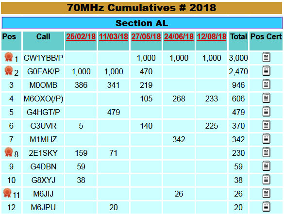
As with PW 70MHz I figured why not have a crack at this series too as I am now QRV. I’d already missed two sessions of the 5 so it was all to play for with 3 session scores needed! Fortunately this series relies on PPK scoring only which suits my non summit Welsh site I decided to use. Also the early afternoon start is rather civilised meaning I could even have breakfast before setting out! I managed to win the last three sessions to win the series.
RSGB 144MHz Trophy.
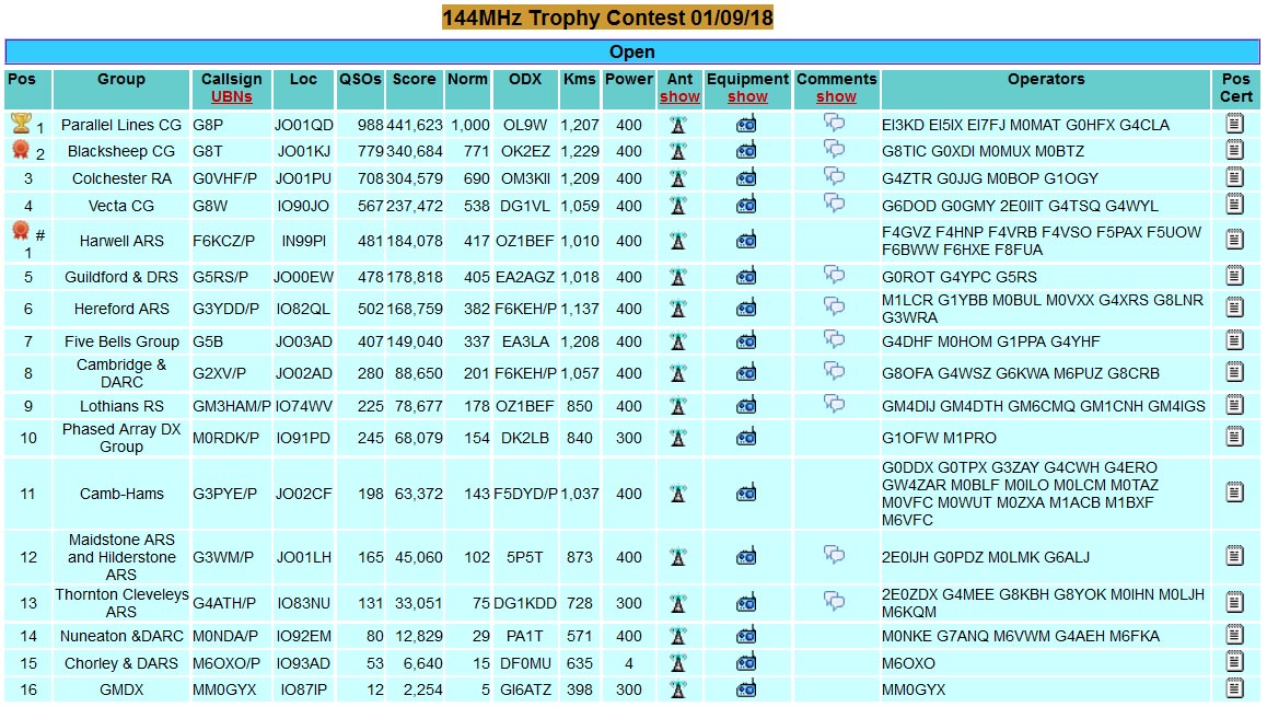
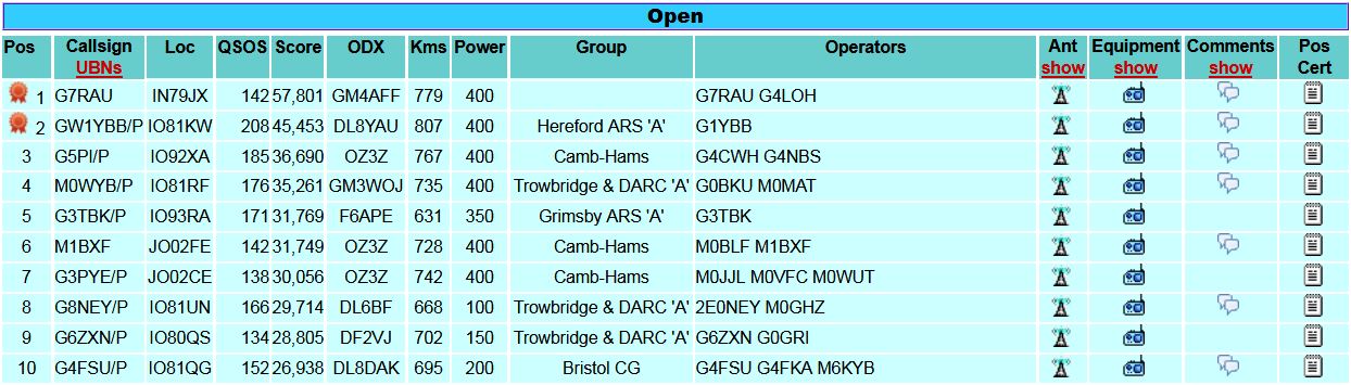
This year some of our keener UKAC entrants wanted to enter the largest 144MHz contest probably in the world as the Hereford ARS. We assembled a good selection of antennas and operators and had a great support team. This was the most luxurious 24 hour VHF contest I’ve ever done. We operated from the top of Clee Hill which has a great take off.
Unfortunately our receive system was not ideal and we expected it to be not perfect but it was a little worse than we hoped. Transmit was very good however which was good. Improvements for next time!
We came 6th in the Open section which isn’t too bad against some of the bigger and more practised teams in this event.
RSGB 144MHz December AFS.
At fairly short notice HARS decided we would make an effort in this weekend event which needs 4 stations (at least ideally) to enter to make a full team of 4 stations. I went to my Welsh portable site but only had one yagi as my plans to use a pair were thwarted by the intended pole (my backpacking mast) to add to my normal portable mast was not man enough. However it was still an enjoyable contest not least for not suffering people moving in on my frequency or 500Hz away all the time (the normal perils of low power!). I did however manage the highest QSO count of all entrants, but not the big PPK of the G7RAU big station in Cornwall.
RSGB 144MHz UKAC.
This year’s 144MHz UKAC was a lot more challenging than 2017. After a good start with a win in January’s event the winter had other ideas for my progress. February and March I was defeated by snow trying to access my portable site. This meant I spent 2018 playing catch up. Mix in some favourable lifts for the East and North East coast, and South, meant some stiff opposition from Tony G8DMU and Andy G6DOD. It took me until October to get 8 ‘proper’ scores in and build a points lead to head the AL section. However two wins in November and December enabled me to pip Mark G6DOD for top spot!
RSGB 50MHz UKAC.
Like 144MHz the snow played a big part in this year’s 50MHz UKAC series for me. Also I started the season running in AR section. However I decided the club would benefit twofold from my entering the AL section, because I could hopefully get higher scores and also rob a few points from the competing guys at the top of that section. I failed to make the portable site in January and March and was away for October which meant I needed November and December to get the minimum 8 portable sessions in to be competitive. I did well in the events I was portable for, once the bedlam creating Es season had cleared off and brought us some nice flat band normality. It’s a nightmare being low power and in the path of most of the country beaming at the Es. You either try for the Es yourself and have multiple people start CQing on your run freq all night as they can’t hear you off the back or you beam inland and hope for the activity. But no-one is interested in IO82 when the Es are going.
RSGB 432MHz UKAC.
Only missed January’s session due to that pesky snow so this bad was a little more positive. I was still using the loaned yagi from Craig M0BUL which meant when using it I had a large chunk of metal in the radiation path. It finally dawned on me so I altered how I mounted the beam and then changed the mast itself to minimise the degradation to my signal. This helped me fight off very strong competition from G8DMU and M0GAV.
RSGB 70MHz UKAC.
This is the only band unaffected by snow access this year. However, not to be outdone, another hindrance was introduced. January was OK but since that event something was installed near my portable site that caused a solid S9 blanket of noise on all headings but 6°. It made my receive an embarrassing joke. People were still hearing me but the only people I could receive had to be genuine 59+ or readable when beaming near North. I gave it 3 months hoping it was temporary but had to accept defeat and move elsewhere. After much head scratching I decided to head to my GW site despite it being a longer and harder site to get to. There isn’t time in the week to reach the summit so I had to settle for a decent spot for North round to East. Takeoff there is fantastic so I can make up points with good PPK. Another downside is zero mobile internet coverage so no KST skeds. However, the fantastic takeoff and (usually) zero noise floor means I can usually hear everyone and anyone. That helped me get enough scores to do well on this band.
RSGB 1296MHz UKAC.
Managed to get to the contest site OK apart from March when I set up lower down where I could get to in the car. Hard work with only 2W against the 10W stations but I did manage a 2nd place which was pretty cool. However I started to take the transverter box apart in order to add a little gain block to get 10W out but time on other projects and part lead times kept me off air for a long time. I actually managed to beat Denis G3UVR and Bob M1MHZ in the December session, and with no Tony G8DMU I snatched a win with 2W. I think this helped me scrape a 3rd position on this band which I am fairly happy with as 2W is damn hard work on this band!

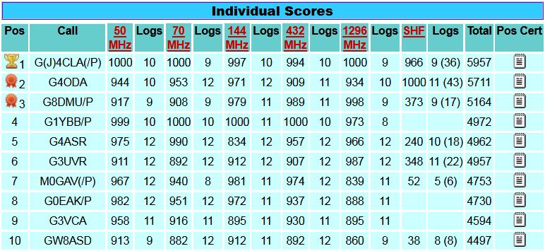
RSGB Overall UKAC Standings 2018.
Out of the 732 total entrants in the RSGB UKAC series in 2018 I managed to come 4th, pipping fellow club member Dave G4ASR into 5th place! I was however the top station only operating on 5 out of the 6 possible bands.
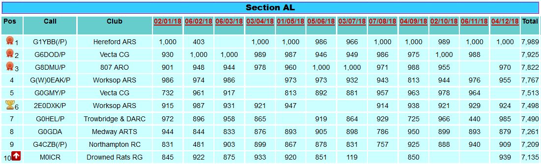
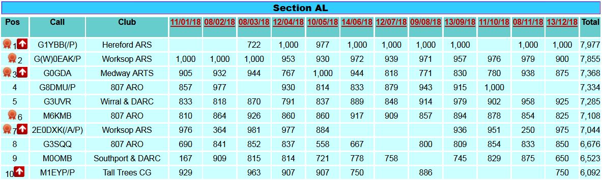
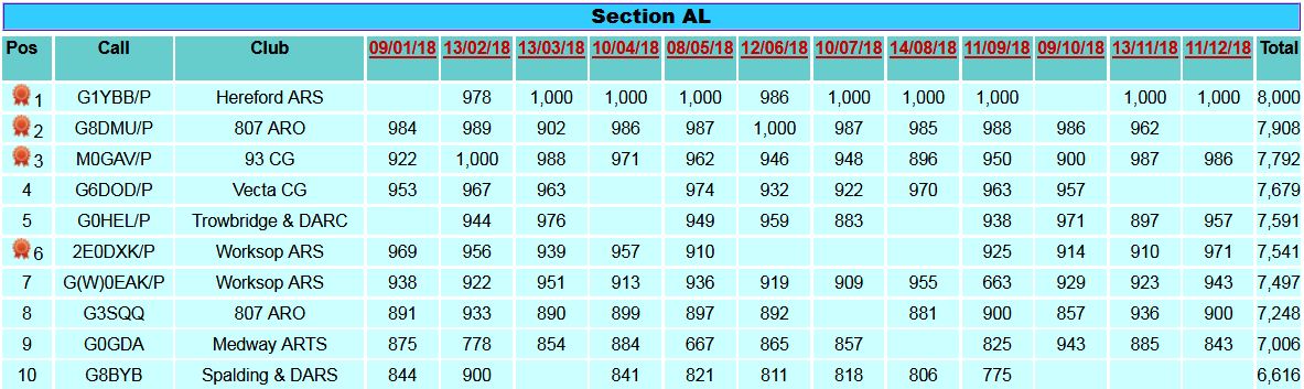
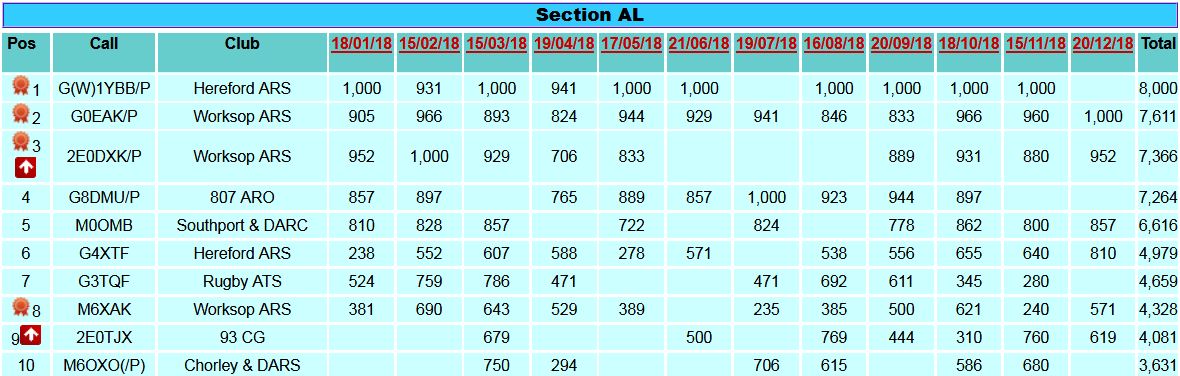
RSGB Local Club section UKAC.
Hereford ARS won the first 144MHz UKAC of the year putting us on the top of the Local Club section. We followed that up with wins in January’s 432MHz, 70MHz & 1296MHz and a 2nd on 50MHz. That meant HARS remained at the top of the table for the entire 2018 season despite some somewhat flexible interpretations of the rules to bump up scores. However, we raised our game with genuine numbers on the air and got some great scores. A fantastic achievement for a sleepy farming city in the boondocks.