This 4th session of the RSGB Backpackers series 2016 is the make or break session for us. Due to being away for the 5th and final session we go into this with 2 wins and a 2nd place. Rob G7LAS is hot on our heels with a win and two seconds. If we didn’t win this then Rob most likely would, and would also win the 5th session making 3 wins to two, an unassailable lead.
So the pressure was on!
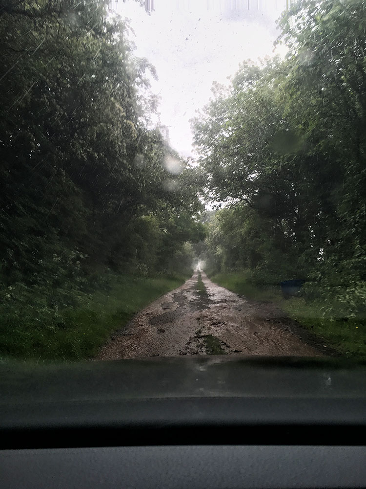
All we could do was continue with our busy work rate and rack up the QSOs as best we could whilst hopefully finding some good multipliers. The tropo forecast was for good conditions to the South and extended just up towards where our location in the Welsh Mountains is. Fingers crossed.
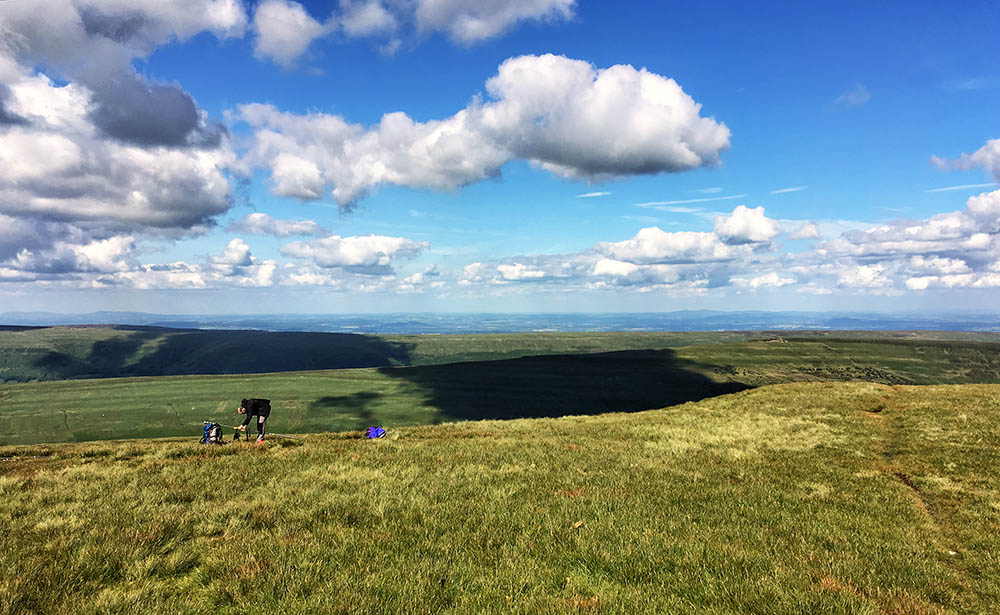
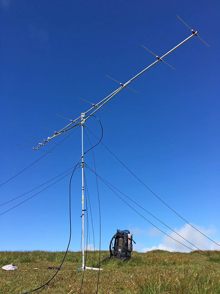
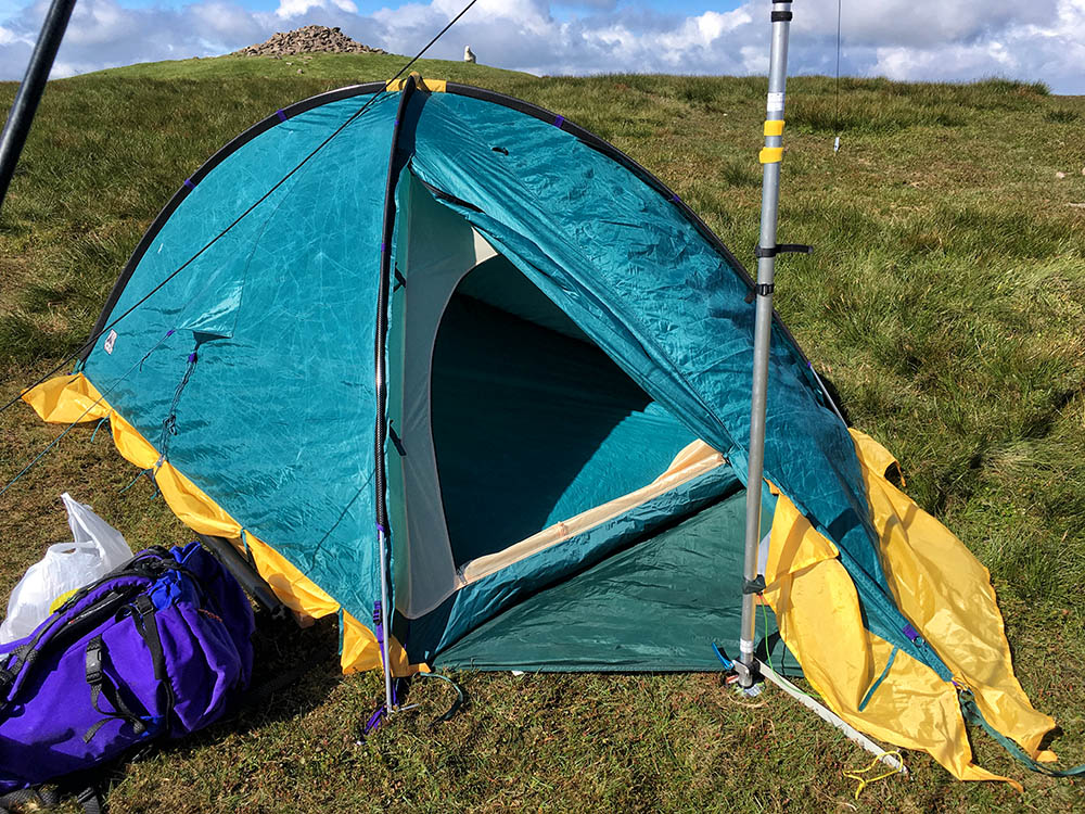
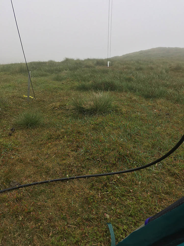
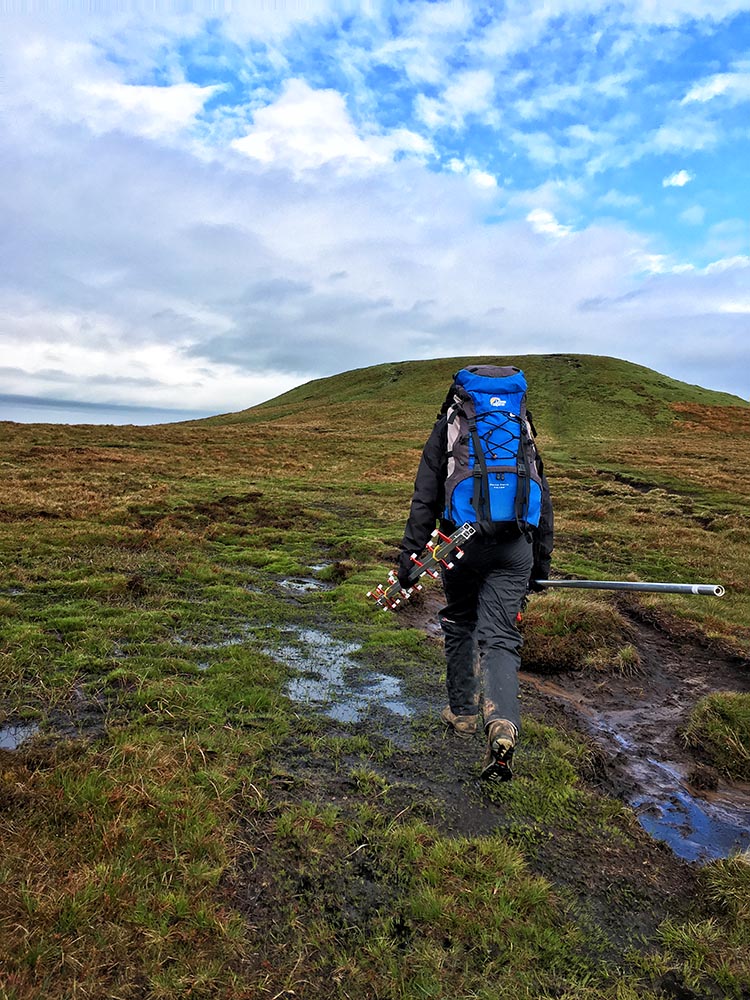
It was a glorious day when we arrived to set up, in fact when I got in the tent it was too hot, I had to take my top off and catch some breeze. Here is a 360°+ pano of our view (click here to view better):
![]()
This 4 hour contest starts 1 hour before both the RSGB Low Power and WAB QRP contests, which are 25W and 10W contests respectively. This meant we had a free band to get started on and didn’t expect to suffer too much QRM an hour in. This turned out to be the case and apart from local strong stations working a weaker running station 4KHz from us we had very little in the way of QRM.
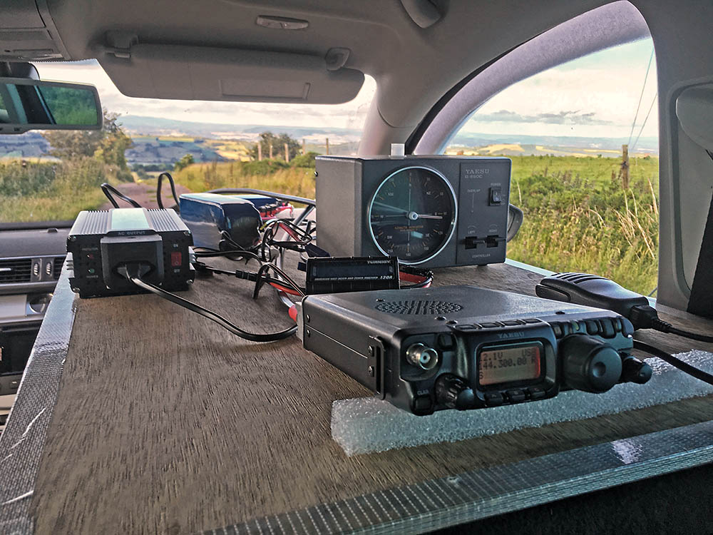
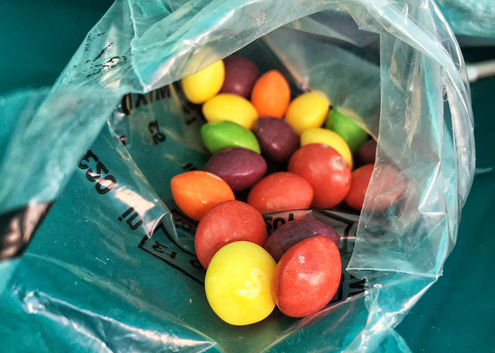
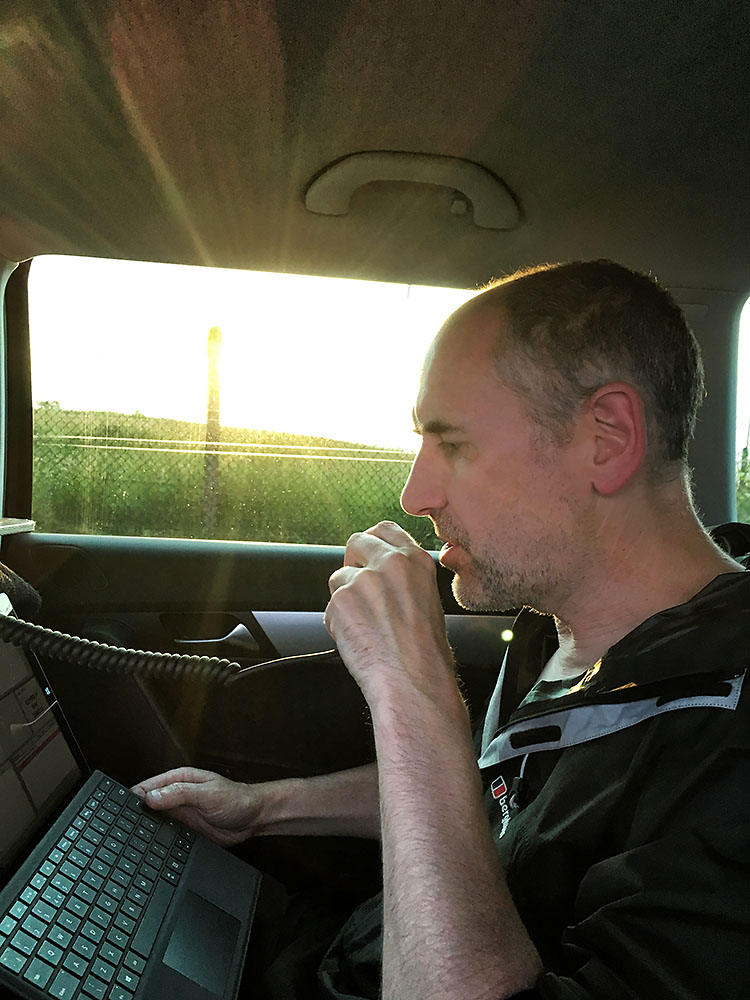
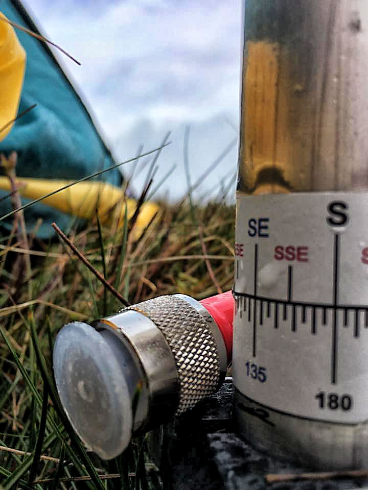
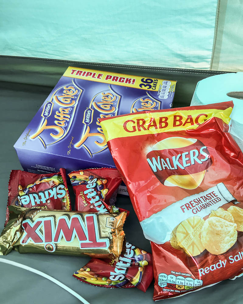
To keep us going we had the backpackers essential supplies:
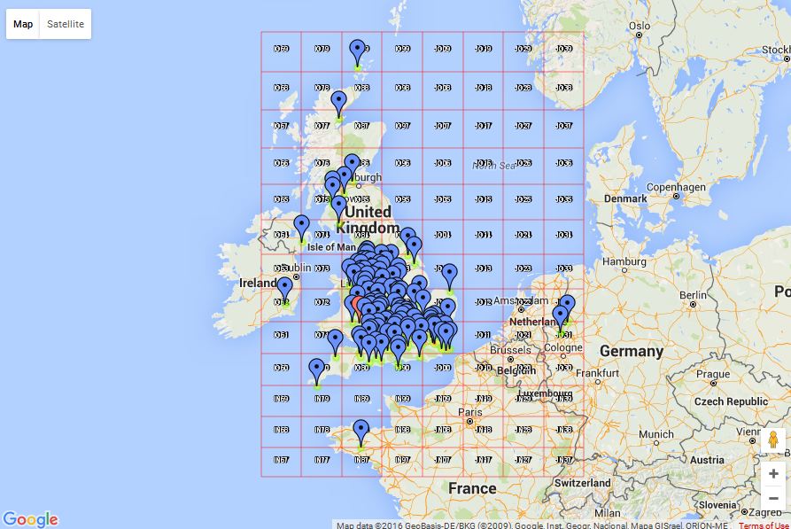
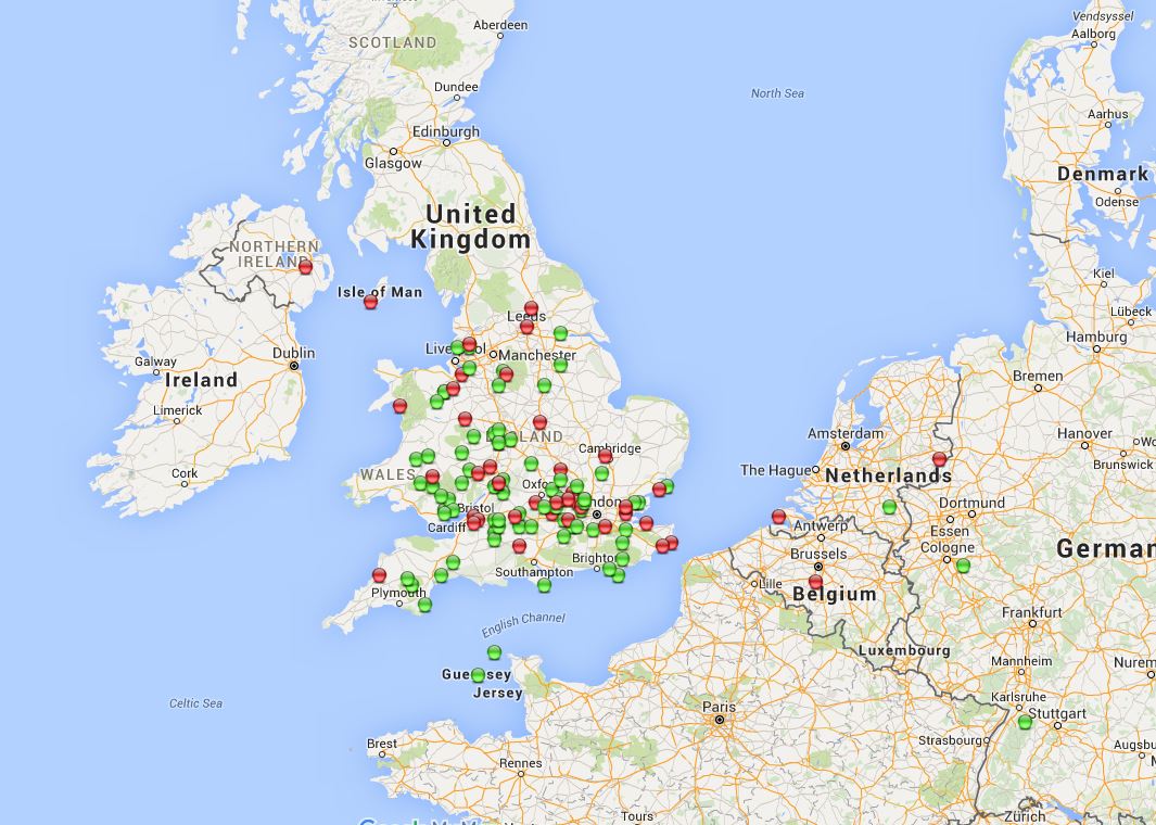
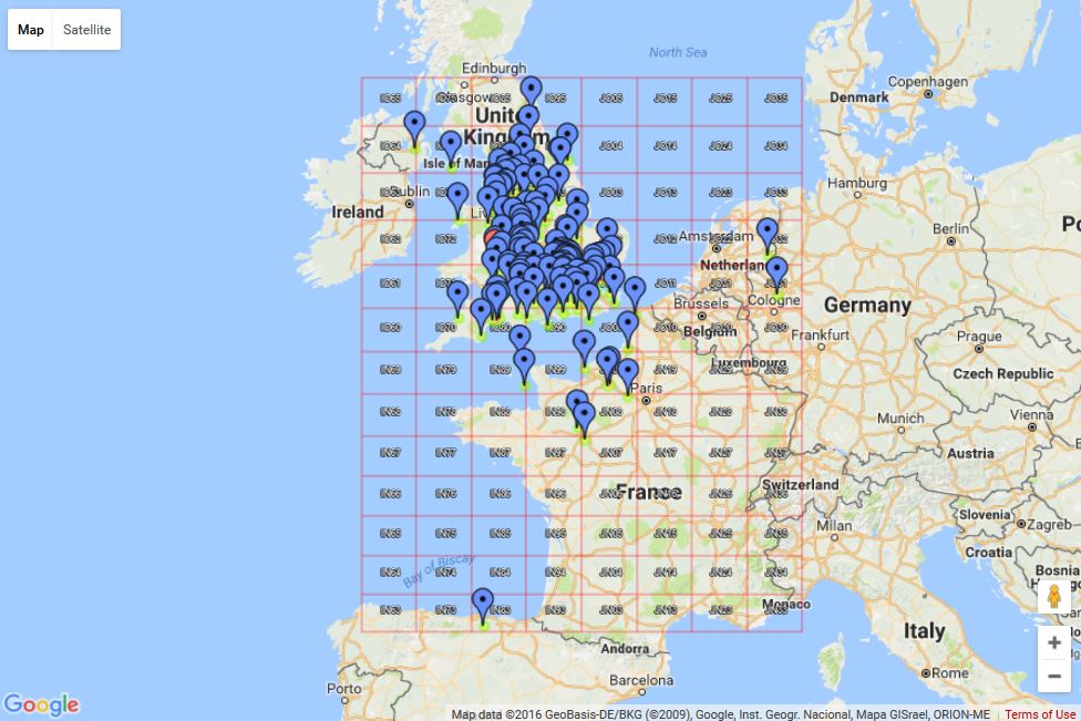
Activity was good and so were conditions. The tropo forecast seemed to be on the ball and we worked several French stations, Germany, Netherlands and even Spain. Again no Belgium. One glaring omission for us was any Scottish stations, but we did get Guernsey, Jersey, Northern Ireland and Isle of Man.
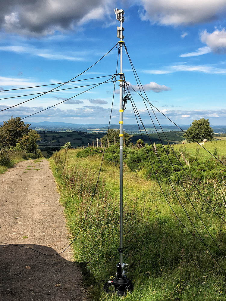
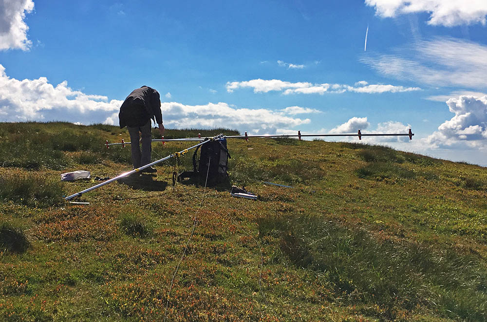
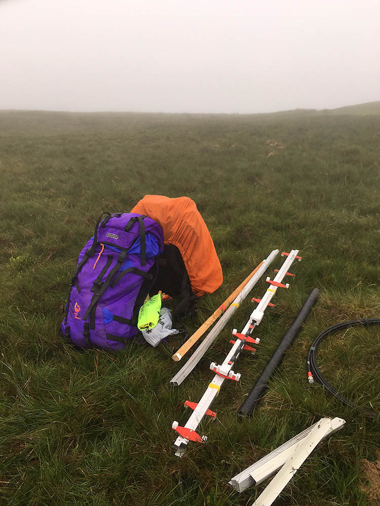
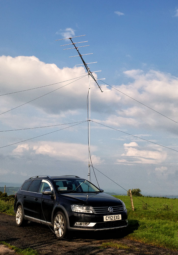
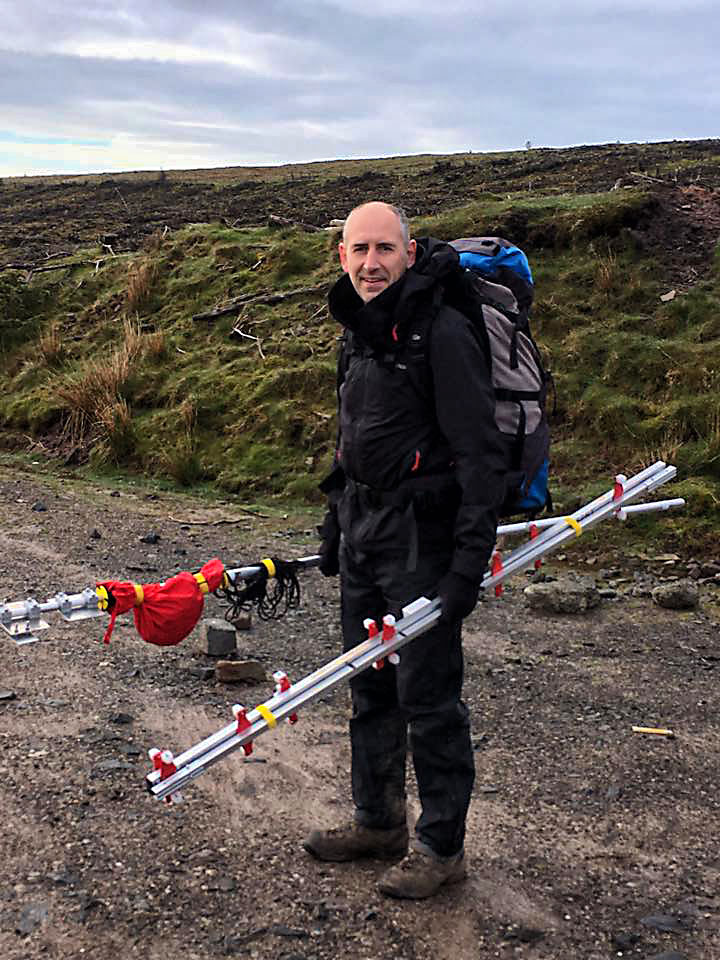
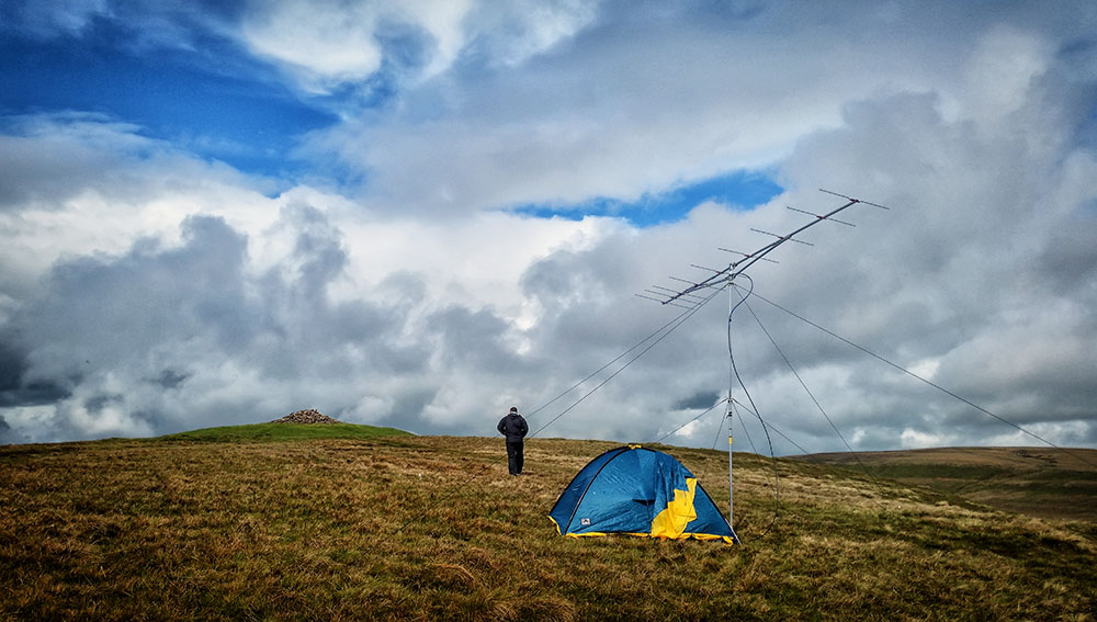
By the time the contest was over it was so windy we were concerned about the antenna and mast even though it was engineered knowing the winds on the exposed point could be strong. The very second the time turned to red in Minos the radio was off and we were out taking down the antenna. That itself is interesting as one thing with telescopic masts is once you start to lower them your guys are no longer doing any good and the lightweight mast is at risk of bending. However we have developed a process for coping with this and soon had the antenna down. Here are some clips of the wind Paul took towards the end of and after the contest:
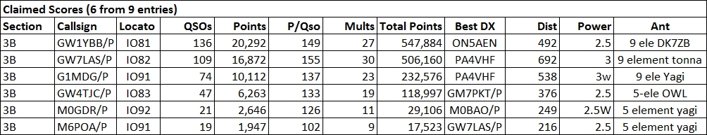
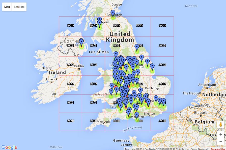
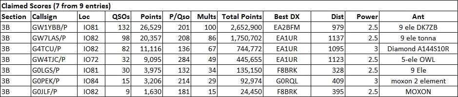
We did really well on both QSO count and multipliers and best DX a little under 1000km. Our score is I think the first score over the 2 million mark in the backpackers this century, certainly the 4th session.
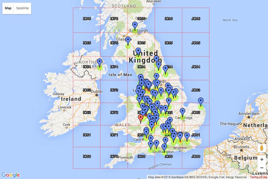
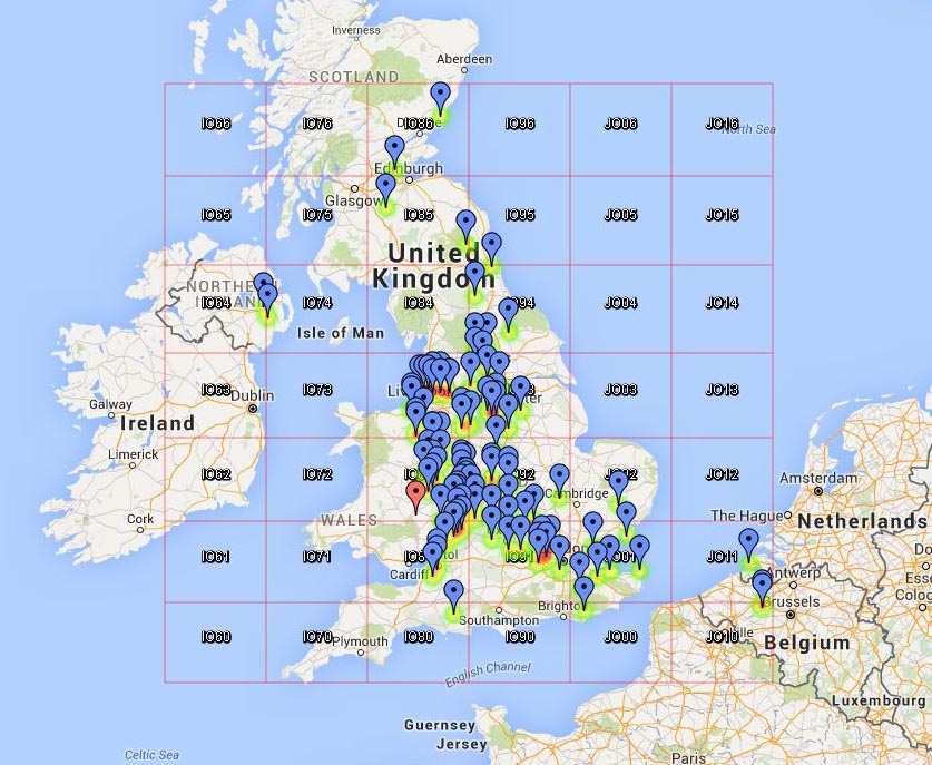
QSO map:
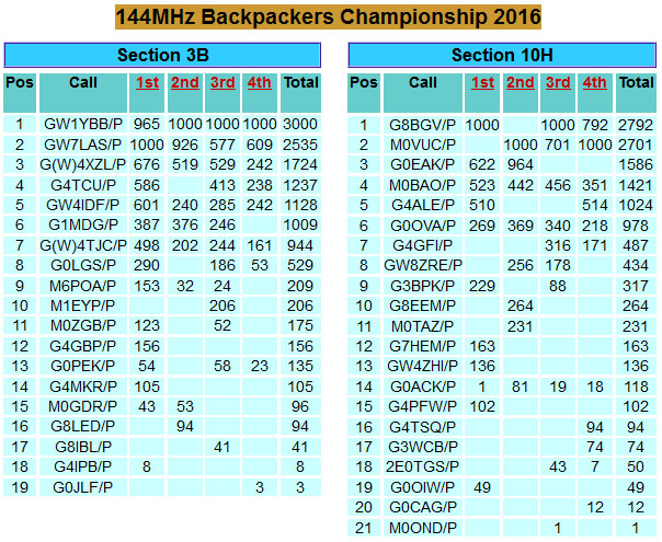
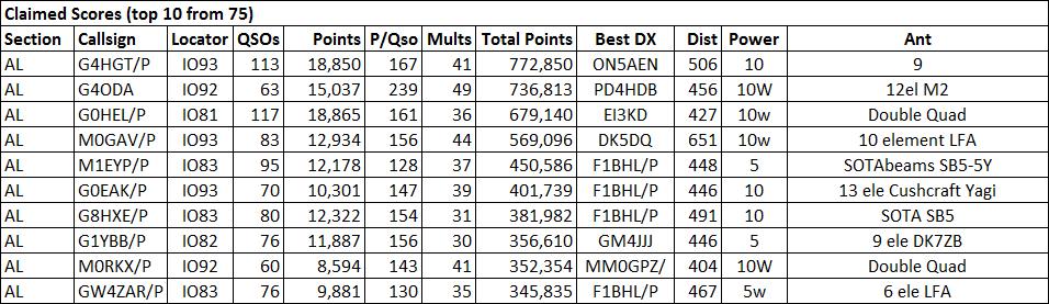
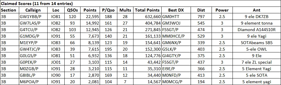
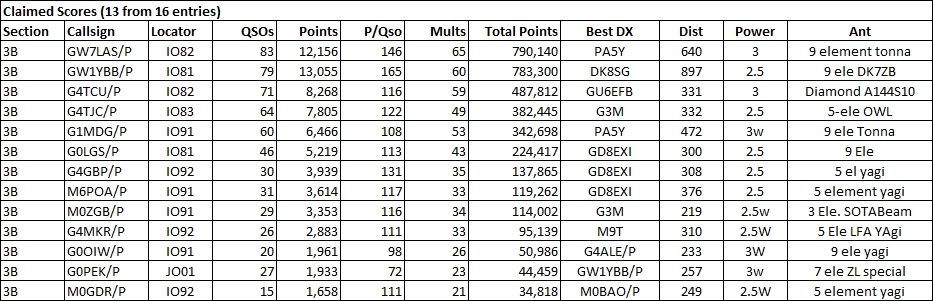
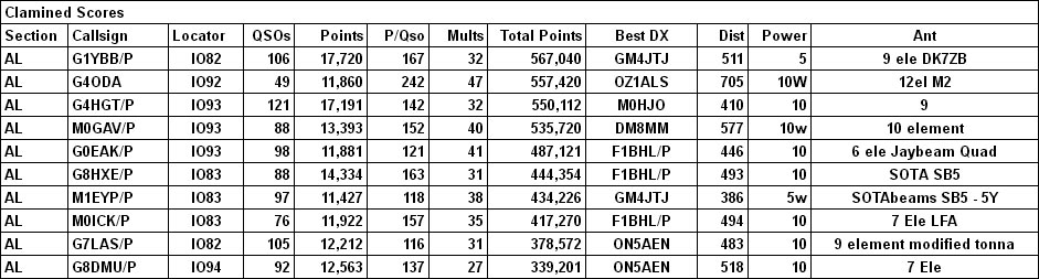
Claimed Scores:
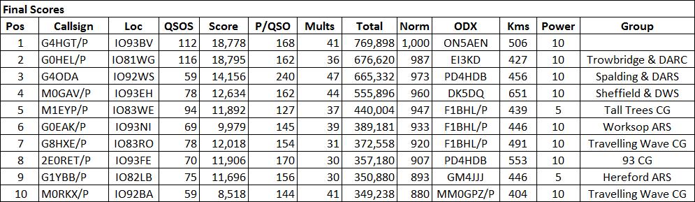
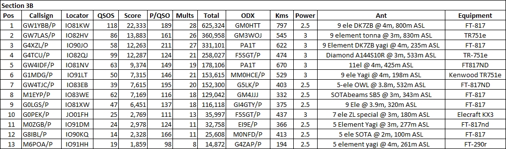
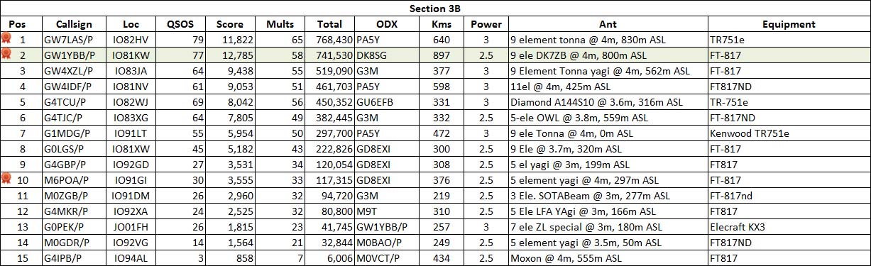
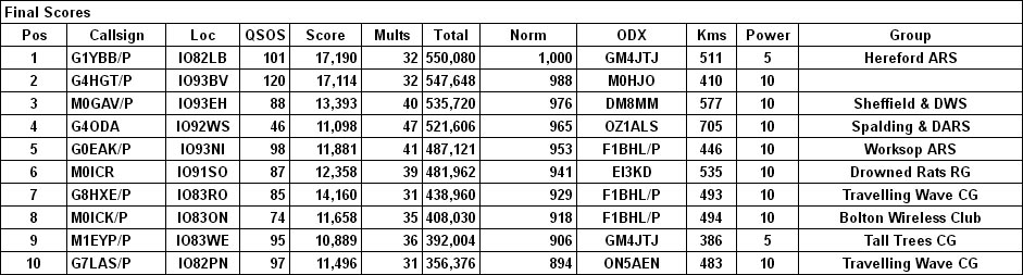
Results:
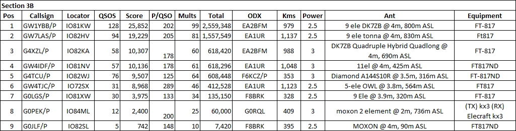
 Full results list (PDF)
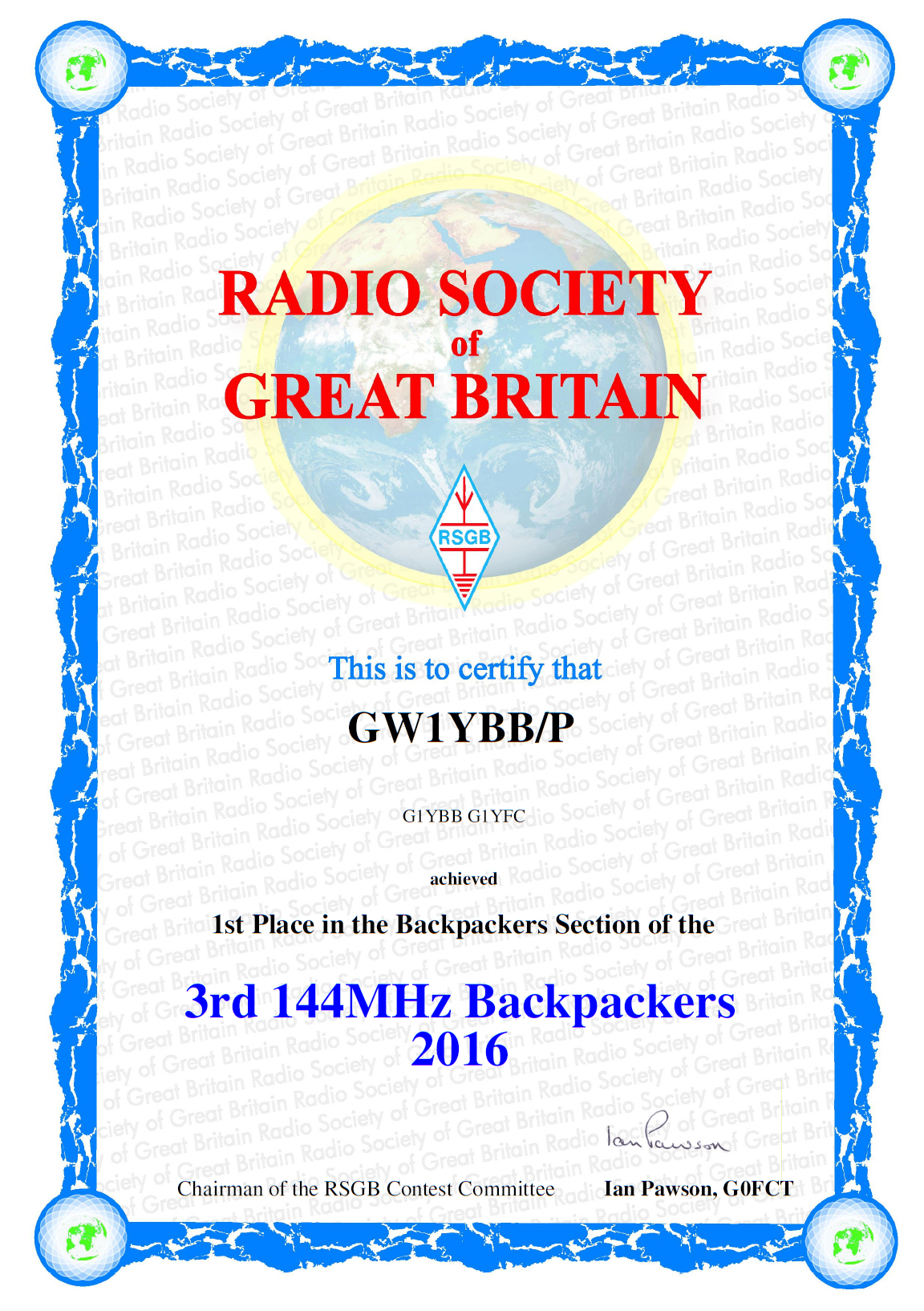
So, job done!! With 3000 normalised points from 3 sessions we have an unbeatable score! Woohoo! Rob G7LAS (as GW7LAS/P) kept us well on our toes but we managed to do the job. I can’t help notice that Rob and us having a good tussle at the top were the only entrants lugging our gear up to 800metres ASL for a great VHF take off. Good to see an even bigger tussle going on in the 10W section.