I recently treated myself to a new HF amplifier from home, an SPE Expert Taurus.
 Like most modern amplifiers there is PC software for controlling it without having to use the buttons on the front panel. This is convenient when you can’t reach (or see in my case) the buttons and also helps prevent the membrane keyboard from wearing out.
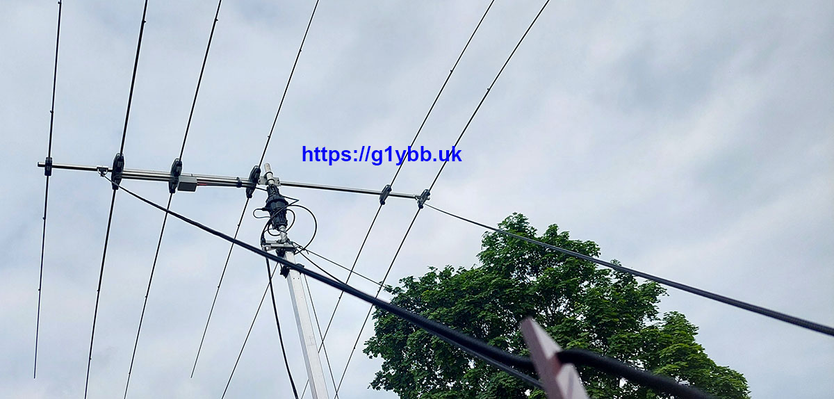
However, in my shack I have an issue with RF when the beam is pointing towards the house (it’s only 8 feet from the house) or on 40m using the vertical (only 20 feet from the house). Despite me having chokes everywhere, on the radio side and the PC cables, radiated RF gets in and crashes the PC software in such a way that I cannot kill the task other than with a PC restart, which is most inconvenient indeed.
So when Jean-Jacques ON7EQ posted in the SPE Expert group that he had made a small remote console to do this it was the perfect answer to my issue!
Jean-Jacques’ page describing it all is here:
https://www.qsl.net/on7eq/projects/arduino_spe_remote_console.htm
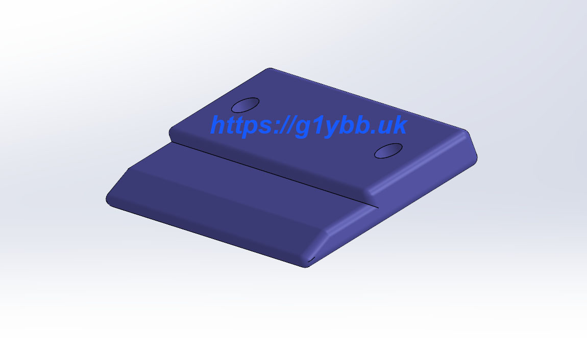
Reading his page I noted that he had used a housing from one of the 3D model download site but he had to make several modifications to make it suit the job. Well, that just won’t do I decided, I will draw up a similar housing that is specific for Jean-Jacques’ great project.
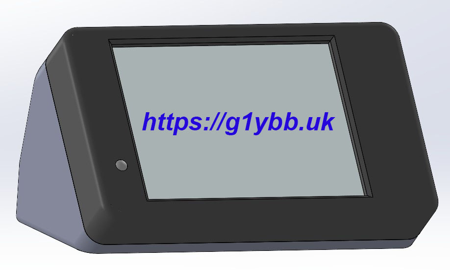
Firstly I decided the Cheap Yellow Display would be better fitted into the front panel then you could wire up the unit easier and made provision for a light pipe rather than drill a hole and use LED body. Also, my prototype, based on the one ON7EQ had used was showing the silver borders around the display window so I tweaked it to cover those and make it look better. I made the cable exit to the rear rather than the sides as I thought this would be neater for most shacks and included a cable clamp. I made integral standoffs to mount the regulator on a small heatsink and a small PCB made from Vero style stripboard. Also a mounting position for the very tiny RS232 PCB and a place for the piezo buzzer and a speaker grill for that. The front panel snaps onto the body without fixings so all fixings are hidden under the base.
 The files are available below, with several different options for cable exits. As I have a cable from my IC7610 to the amplifier which powers up the amp I didn’t require the power up circuitry and so didn’t need a cable hole for that. I brought the 12V DC in on the speaker wire style twin wire so have a separate entry for that.
G1YBB design housing files
As I didn’t want the power up circuitry my BOM does not have those but the parts are detailed on ON7EQ’s page. I had literally no parts in stock for this so my costs included everything apart from the 3D printed enclosure. Some parts I had to buy 5 or 10 when I wanted just one and a reel of cable when I only wanted a short length. Even so EVERYTHING came to just £52.18.
Click the image to open a PDF with clickable links to the part sources.
 The circuit is very basic but as a guide here is my layout from which you can copy the PCB size should you wish. The case mountings in my design are spaced to match the 0.1″ pitch of the stripboard.

There is not a lot of wiring but it is quite fiddly, mostly the RS232 PCB as it’s tiny and the data connections are only surface mount pads so care is required to not stress those and rip them off.
The recess for the RS232 PCB is a nice fit, check the PCB goes in OK before wiring. I ran a file over the break off edges to smooth them off but not too much to make it loose. The recess is designed to take the PCB with the IC upwards and the RS232 side towards the cable exit. This should mean the surface mount capacitors on the rear are towards the clearance pocket in the PCB cradle.
The piezo buzzer was a press fit into the recess I’d drawn for it but I also used some hot glue to keep things in place, and also as strain relief at the cable exits from the display PCB.
I tested it works before finally fitting the RS232 PCB into the enclosure.
UNPLUG THE USB LEAD FROM AMPLIFIER BEFORE TESTING.
The remote port will not work with the USB cable attached and the amplifier manual states damage is not impossible if both are in use.
I had to swap the serial data wires from the CYD to the RS232 PCB to the original circuit Jean-Jacques had. You may or may not need to so the same.
Here is my unit before fitting the front panel.

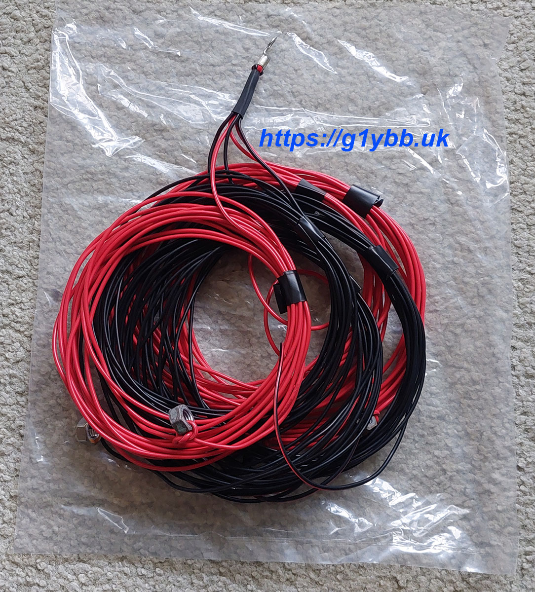
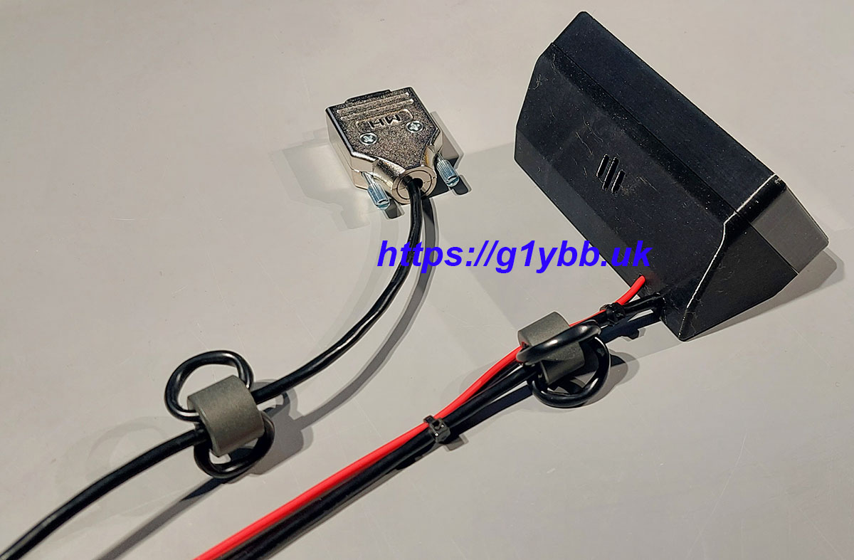
Here is the rear view. I fitted a ferrite at the amplifier end and the console end.
Many thanks to Jean-Jacques ON7EQ for his design of the SPE Expert remote console.