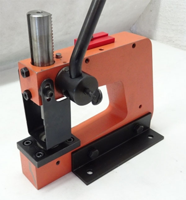
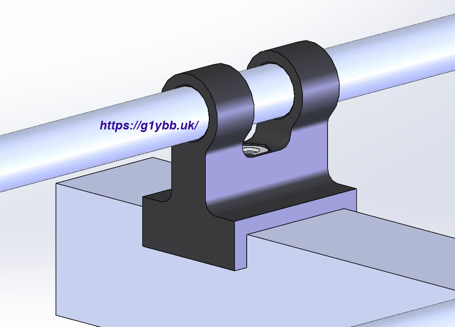
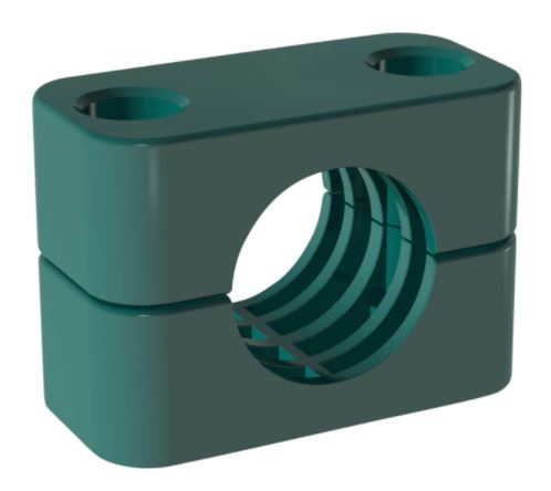
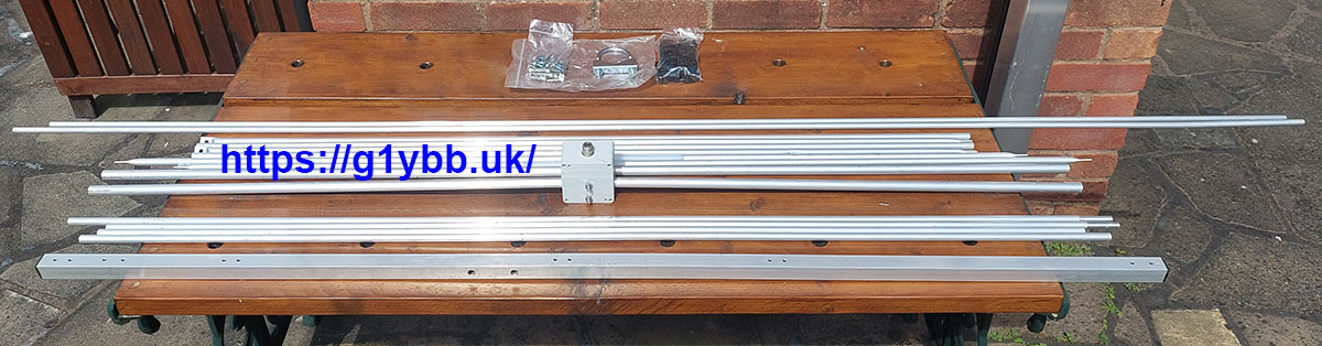
This may not seem that radio related but an arbor press is a very useful tool, even if it is not used that often. Most recently I have used it to press in my YBB washers into Stauff clamps for an antenna build. I’m tuning it up in order to use a 5 inch vice based brake press set to do some sheet metal folding, mostly as I don’t actually own a vice to use the brake press set in but also because if I did I would only have a couple of inches of throat to bend whereas the arbor press will give me about 5 inches. These are great tools and not expensive but out of the box they don’t feel or work that great so I decided it needed a simple tune-up.
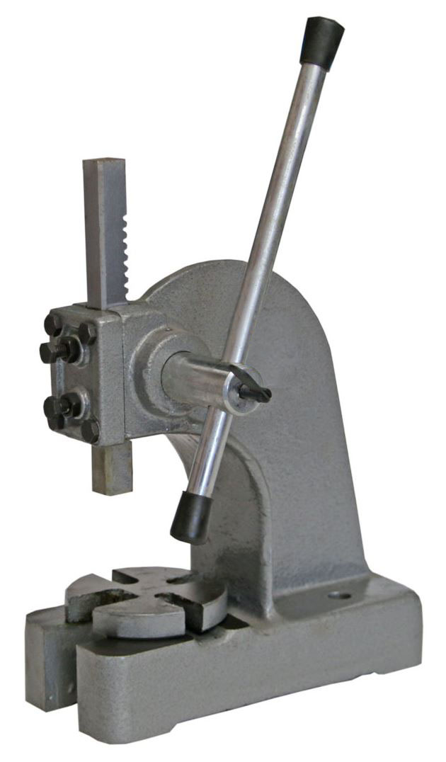
I actually bought an arbor press because I could get what I really wanted which was a lever press RS (Radio Spares) used to sell. If you have one of these in good condition, I need it!!