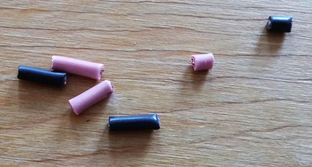
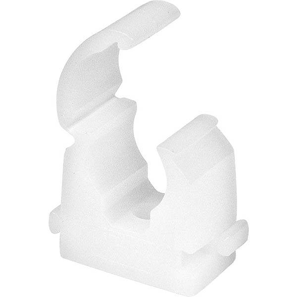
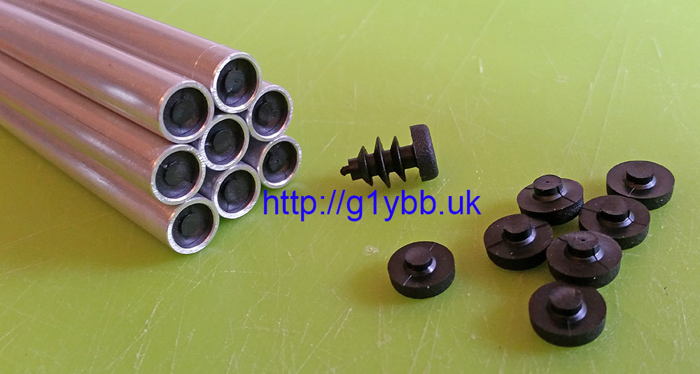
When making my yagis I prefer plugging yagi dipole ends so water cannot run down the tube and enter the dipole housing with its corrosive end results. Also, it does stop spiders moving in and making a right mess everywhere.
Many people do not like to add caps to the elements for concerns over altering resonance, so I just cut the cap off and push them in so they are fully inside but water cannot enter. Simples.
These plugs were from nuxcom.de but he has ceased trading now but they are available at various places including Tino’ Funkshop but these days if you are in the UK it’s best to look more local.
I planned to build more 144MHz & 432MHz DK7ZB yagis for contesting to use in arrays so I wanted to ensure I could make them accurately and repeatedly and also without taking forever doing it! Thus I needed to come up with an efficient cutting jig to make accurately cutting yagi elements to size fast and reliable.
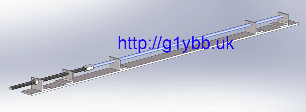
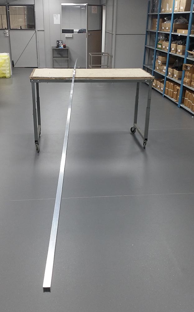
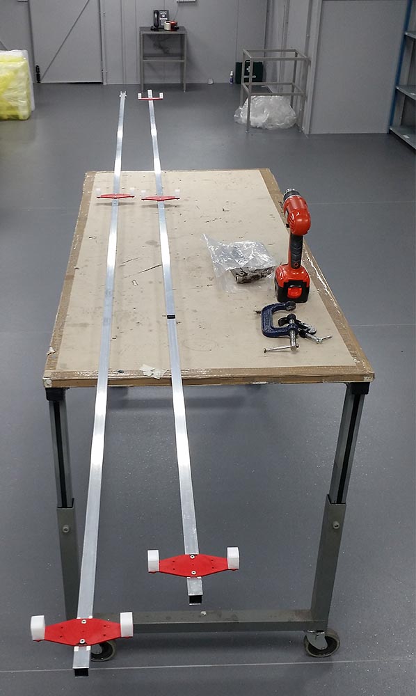
I would use some threaded bar to adjust and set the length and steel angle for the supporting the aluminium tube and cutting the length. First I calculated the range of length between the longest reflector and the shortest director then a quick knock up in Solidworks gave me the length of stud required and ideal places to weld the angle to do the cutting. The studding is M12 because a nut for M12 will take a 10mm ali tube with a little clearance. The long M12 barrel nut (Screwfix, few pence) is locktighted in place. From the left the angle brackets have the following holes: 12.5, M12 tapped, 10.5, 10.5, 10.5:
Some cutting, drilling and tapping later and I have this (the observant will note it’s not exactly the same as the intended design-more on that accidental stroke of luck later!): continue reading
Now it’s towards the end of June and I have been listening to the other club members I chat and contest with reporting on all the times 50MHz has been wide open on sporadic E, I decided today I would knock up a simple antenna for 50MHz for the garden. My location is not suitable for any real antennas due to neighbour issues so I thought I would make a wire delta beam and mount it fairly low as I have a suitable 2m length of plastic pipe I could use for the cross boom. A quick look at the design scuppered those plans as I had no suitable 75ohm coax here.
I then considered a simple aluminium dipole as I have loads of 1.5m lengths of 12mm tube in the garage. Then it came to me in a eureka moment. A good old trusty inverted vee would be easy to make and do the job nicely!
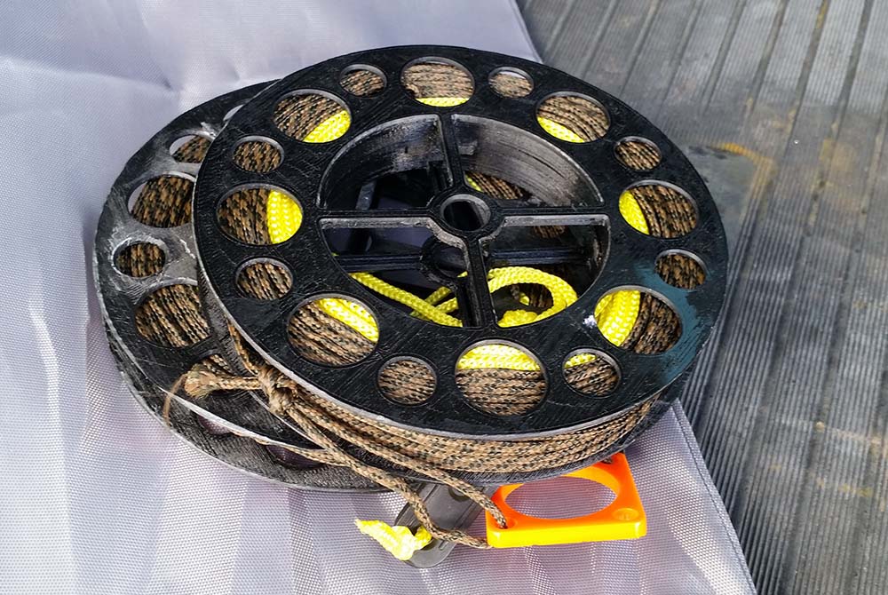
Since I made my first 20m inverted vee dipole I have since butchered it by cutting off the coax to use elsewhere and it has been lying around the garden for a year or so in the grass in the corner of the garden. Rescue that and put new coax on and I am good to go!
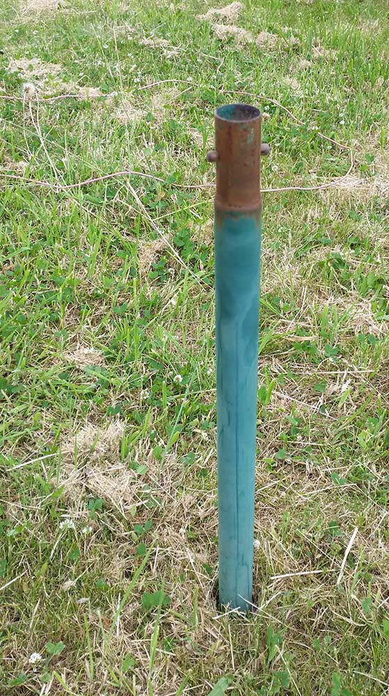
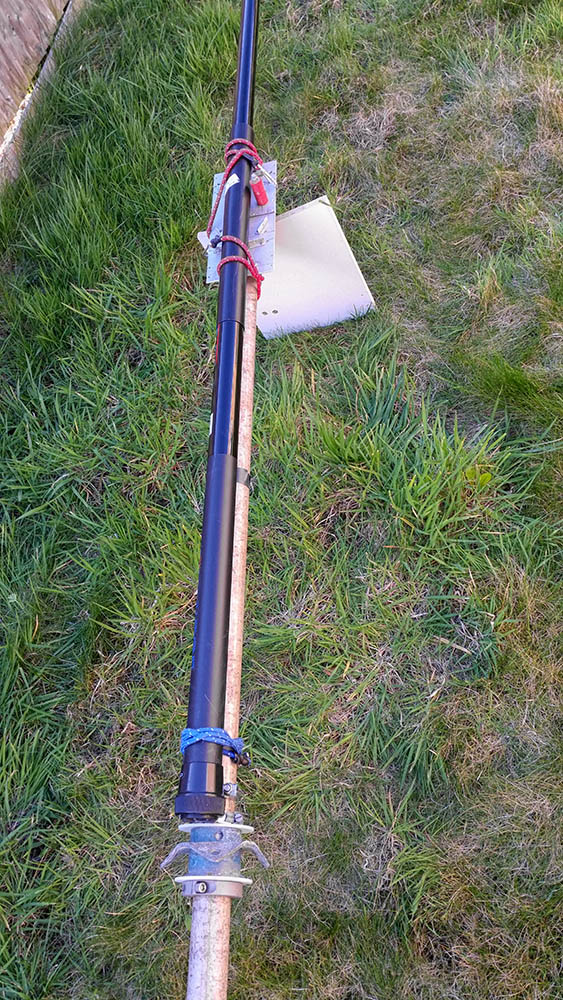
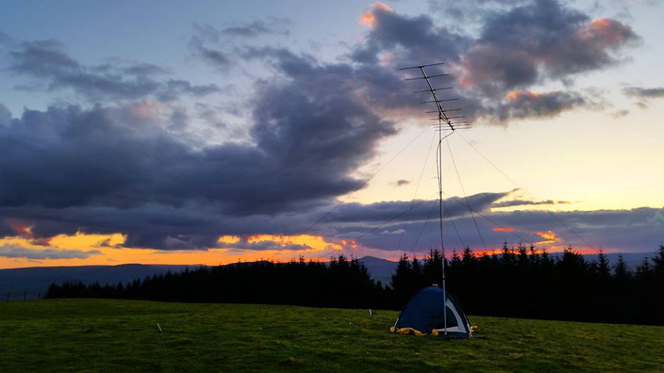
Next (as seen already above) I needed a pole. I took the bottom 3 sections from my 8m SOTA fishing pole which gives me about 3m of lightweight but stiff pole. In the garden there was fitted a rotary washing line with a two part stem set in the ground. Amazingly it was the perfect fit for the bottom section of the pole! The two sprung plungers even stopping it flapping around:
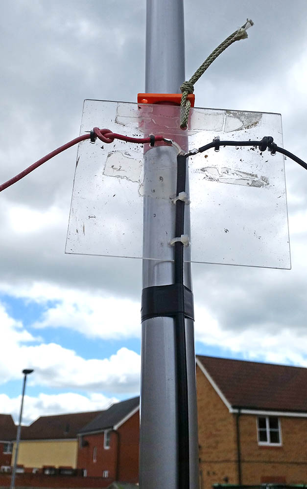
Into the HF antennas odds and sods box and I got out one of the SOTAbeams lasered guy rings I bought to hang the dipole from. I slid it down to a reasonably but not excessively snug point and wrapped some tape around below that to stop drifting lower and possibly cracking as the plastic is fairly brittle feeling. I also sealed the feed point with liquid insulation tape which is great stuff and taped the coax down the pole to take the weight of the coax, which is longer than I need and only RG223 but I am just looking for something to get on the air and do some tests:
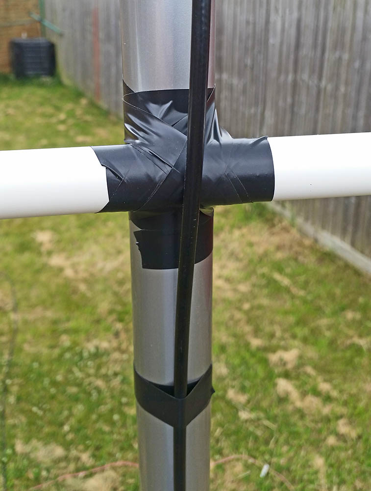
With my HF dipoles I usually peg the other end to the ground with a length of string to insulate and keep the voltage maximum point off the ground but that really didn’t seem a plan. So that delta beam boom was called into play as a dipole spreader:
It’s literally just lashed on with insulation tape:
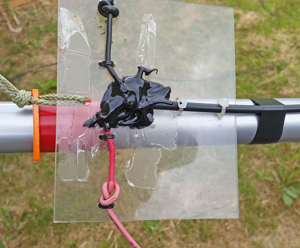
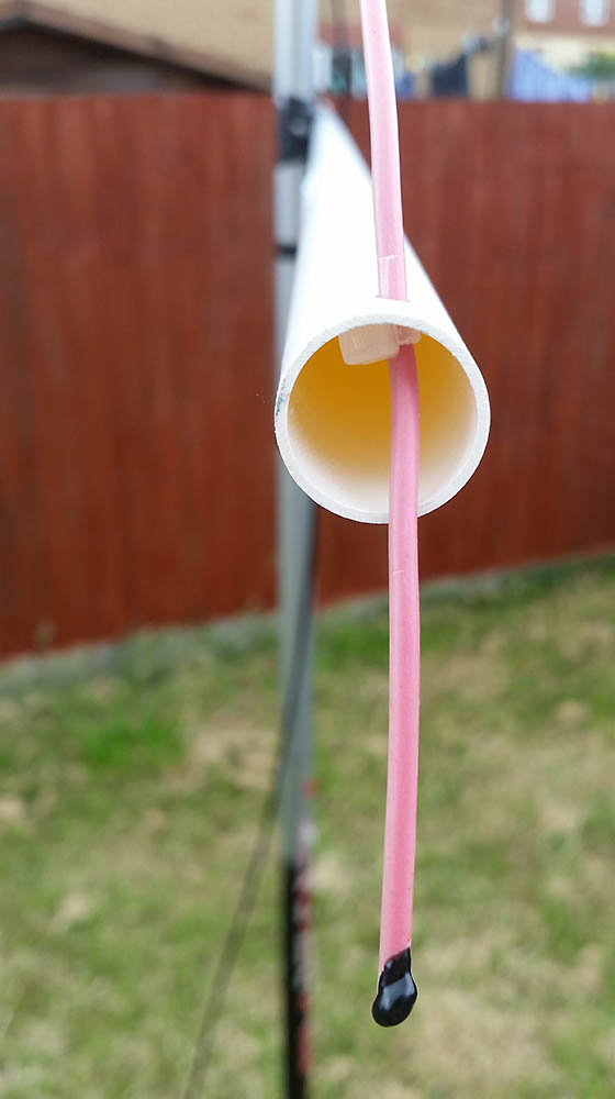
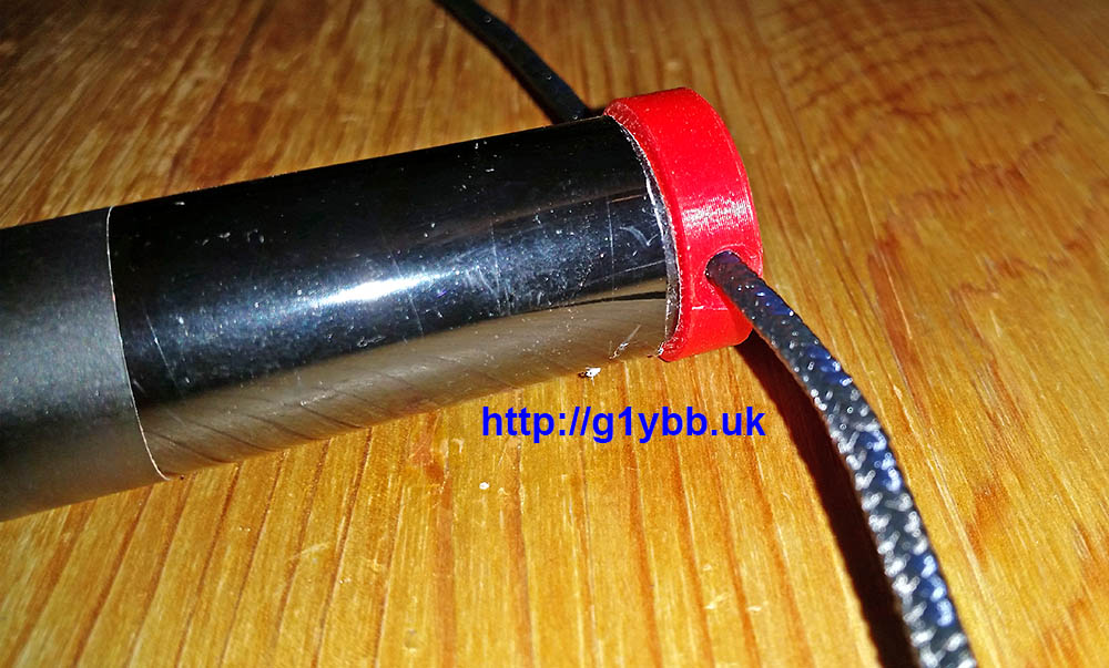
At each end I drilled a single hole to thread the wire through which actually retained the wire quite well due to the tension and angle. But I backed that up with the ubiquitous cable tie. Also visible is a blob of the liquid insulation tape on the end of the wire to stop water seeping up the wire via capillary action:
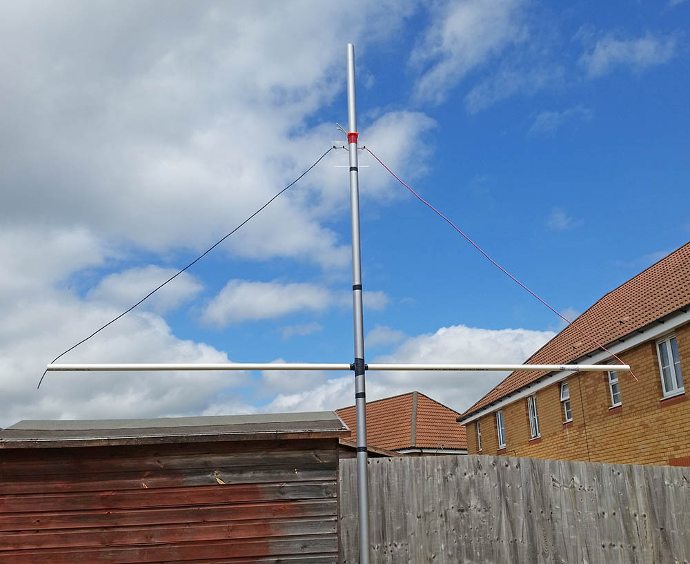
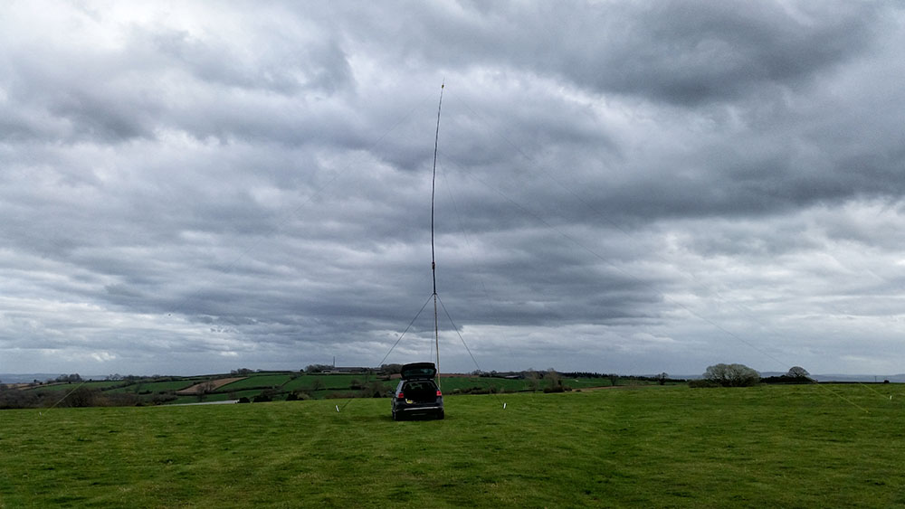
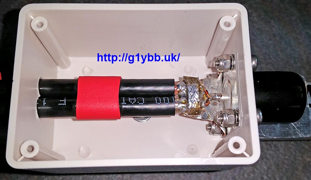
Here is the finished set up ready for tuning. On the left of the image you can see the coax running into my custom wall mount coax connector box:
Talking of tuning…
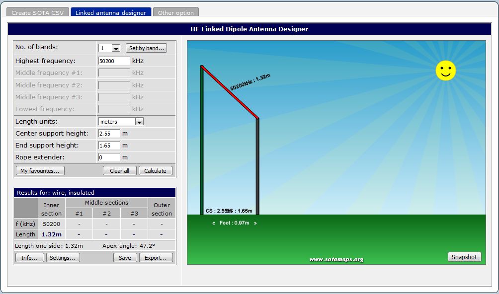
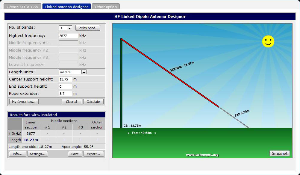
To ‘design’ the dipole I use done of my favourite sites I use for all my HF dipoles over at sotamaps.org. (Click on the 2nd tab for the calculator). I put in the centre height measurement from my set up and adjusted the end support height to get a little under a metre horizontal distance between mast and end support. You can set the wire type via the settings button. You can see it offers me 1.32m for each side. So I cut mine to 1.42m to start as it’s always easier to trim than add!!
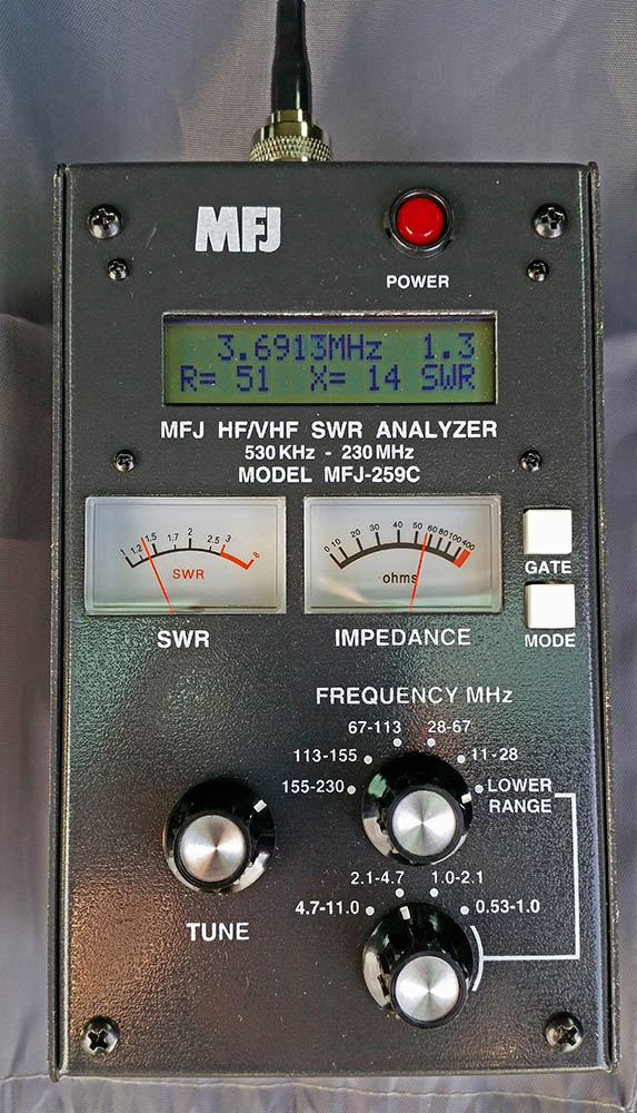
First measurement showed beautiful resonance a little under 50MHz, so I trimmed 10mm off each end. Nearly at 50MHz, so 10mm more. Resonant now more in the CW end so I took off another 5mm. The final cut length is actually 75mm longer than the designer suggested, so it could be my selection of wire should have been for a thinner one or thicker insulation than I chose. (that’s ex red wire with a dose of UV fading applied!):
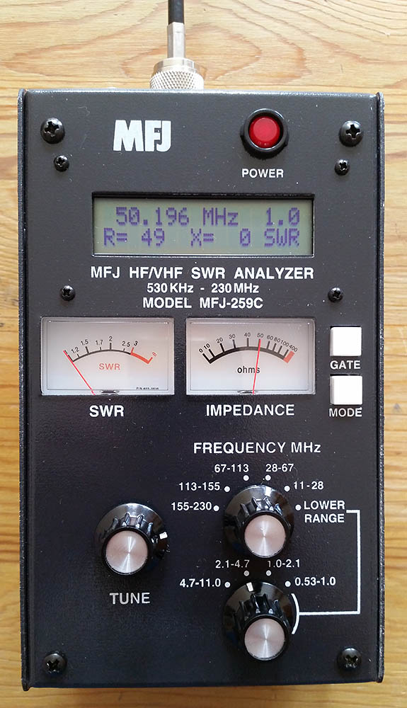
SWR 1:1, zero reactive component and 49ohms resistive component (50 ohms a tad higher up the band but still in SSB section). I’ll take that!
Plugged into the trusty Yaesu FT-857D and a quick scan showed some Es stations calling. Found an EA station and called him, replied to me first time! As did the next 4 stations. Nice one!
So there you go. It is dead easy to get on 6m even with very awkward neighbours and small gardens. 50MHz truly is the magic band when those Es open up too!
My local club Hereford Amateur Radio Society has been embracing the RSGB VHF and UHF activity contests but also some members have been taking part in the RSGB 80m CC series of contests which have SSB, CW and Data sessions. I wanted to join in so needed at make an antenna, which I decided should be a trusty inverted vee dipole.
My first consideration was how was I going to support the centre high enough. I have an 8m and 10m fishing pole but neither are really high enough on their own. So my solution was to attach the 10m fishing pole to the top of my VHF portable mast (a 6m scaffold pole) which will get me the centre of the dipole about 14m high: Off to the SOTAmaps dipole calculator website (link on my useful links page) to calculate the lengths:
The fishing pole is pretty flexible using the upper sections so I have a pair of guys lower than the dipole to stabilise it a little made from thin but strong cord. These will go at 90° to the dipole, using the dipole itself to steady the very top of the pole:
Typically it was a pretty windy day when I set it up on my favourite test setup hill:
As the wire is quite thin it’s fairly narrow band but I got a reasonable match mid band:
All ready to go.
Apart from the fact that my favourite test site and intended 80m CC portable operating site Westhope Common, that I have been using on and off for about 35 years now has a resident that hassles everyone and anyone who goes up there, and has hassled me each time I have been there lately. So I need to find another site.
Towards the end of 2016 the rules and days for the UKAC series of RSGB contests were changed. The 50MHz and 70MHz UKAC events were moved to the 2nd and 3rd Thursday of the month respectively. This opened up more opportunities for me as working a Tuesday night contest means rescheduling my Tuesday to a Wednesday and means my Wednesday is busy as heck and it’s at least Thursday before I can even look at the tablet to get the log updated. But a Thursday I am usually free so I can get on another band. As I have no 70MHz Tx capabilities I decided 50MHz was the way forward for me. I have an old home made 5 element yagi we used to use but I wanted a newer better performing yagi. I am getting awesome results with my 144MHz 9 element yagi I decided another DK7ZB sounded ideal.
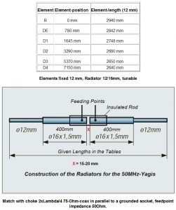
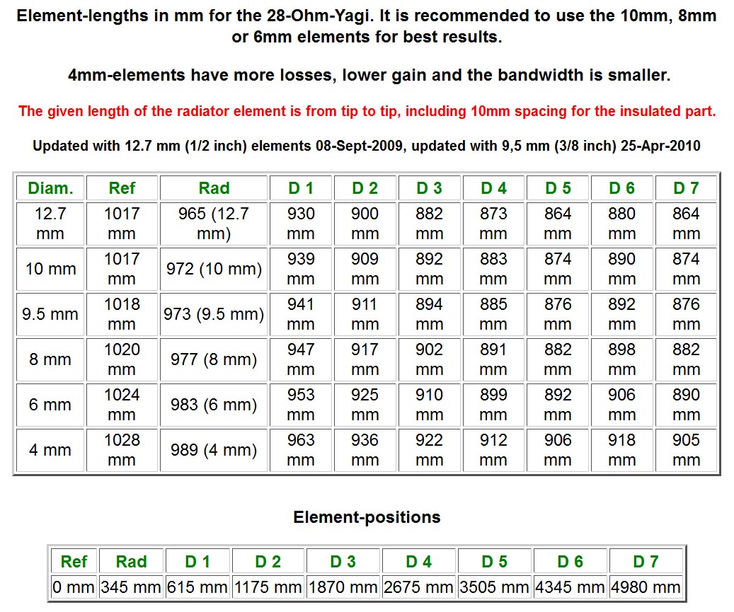
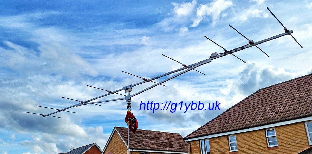
I chose the 6 element 7.2m boom version as I plan to only use it car portable and it’s only 1m each end longer than the 144MHz yagi I’m using. Also it has a great SWR curve. All dimensions are available on Martin DK7ZB’s site:
This design only had figures for 12mm elements. That was OK as I can get 12mm pipe clips like I used in the 144MHz yagi. But it turns out buying 12.0mm tube in lengths greater than 2000mm in the UK is exceedingly difficult. It had been suggested to me to use 12.7mm tube as that would be easy to buy in the UK but would require recalculating the element lengths. Not only that it would prevent me from being able to use the fast fit pipe clip I wanted to use. After much searching and asking in various places I had to admit defeat and arrange with Attila at nuxcom.de to ship (at some considerable expense) some 3000mm lengths of 12mm tube, along with several other antenna parts and also some 3000mm lengths of 10mm element tube.
For this yagi, unlike the 9 element for 144MHz, I had no plans to take it backpacking portable so I decided it only needed a 2 part boom. I was easily able to get 5000mm lengths of 20mm boom for this. 20mm is quite small sized boom for a yagi of this size but my element mounting plates are designed for 20mm boom only. I’ll be using truss supports and side supports if required to stop it flexing too much. The 5.1m long 2m yagi was nice and sturdy with its trusses in high winds on the top of the Black Mountains. Although it’s only 1 metre longer each end, it makes for a big boom!
Once the element positions were marked up the 5 parasitic element clips were fitted in the same manner as the 144MHz 9 element. On this yagi the driven is too big for the element clips so that will need a more conventional box:
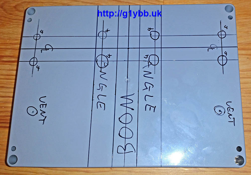
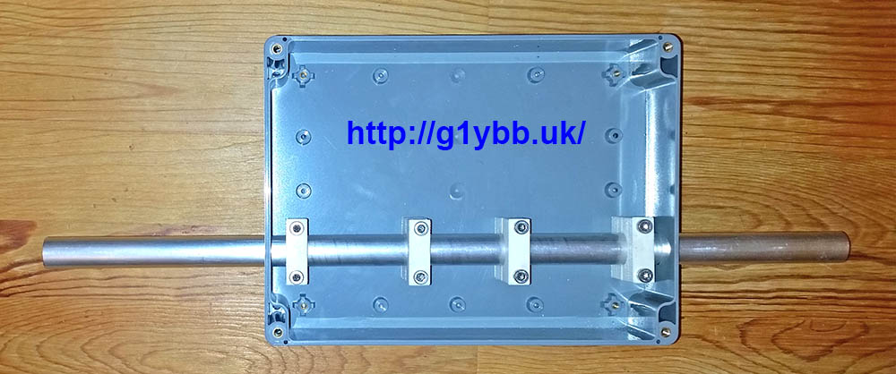
For the feed box I decided to go for a beefed up version of that I did with the 144MHz 9 element. I chose an ABS box from Farnell as it is quite thick walled and with a decent lid should be pretty stiff and is also IP65 rated (before I start drilling it). In order to get a suitable height so the driven element 16mm sections could be on the same plane as the parasitic elements it came in quite large at 200 x 150 x 55mm but that is OK as the driven on this 50MHz is quite big:
Here it is marked up for drilling. Marking needs to be spot on as this is what makes the driven element parallel with the parasitic elements in both planes so is crucial!
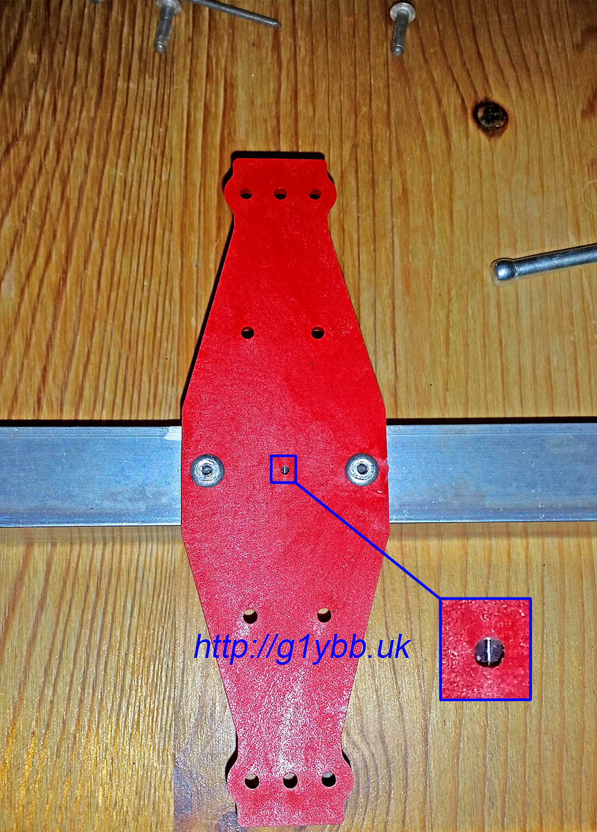
This is the centre point of the dipole box used for locating it on the boom in exact position:
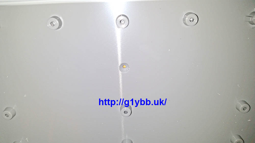
To enable stability and strength for the 3 metre driven element I am using some 19mm angle. The sighting hole above lines up with the centre of the scribed line:
To mount the two halves of the dipole I got my good friend Paul to 3D print some two part clamps in ABS to my design so the centreline height of the driven element above the boom matches the parasitic elements so all elements are in the same plane. Here are the clamps after drilling and fitting to the box with some 16mm tube to check alignment:
To fit the dipole box I drilled and tapped an M2 hole in the centre point of the boom on the scribed line as seen above and screwed the dipole box in place using the 2mm sighting hole. I then fitted the reflector and first director and ensured they were all parallel and drilled the box to fit the two angle pieces:
When I bought the element materials from nuxcom.de I also bought their dipole centre for 16mm tubing:
Which is very chunky and strong. But the 16mm tubes fit inside the joiner and I couldn’t see how one would get a good secure contact to the elements. So I got another good friend Ed to turn up a piece that would fit inside the elements like the nuxcom one for 10mm elements does. Here is the mechanically finished dipole centre:
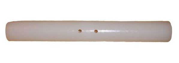
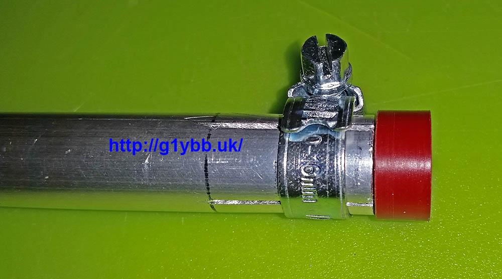
The eagle eyed may be wondering what the red things are in each end. Well as I am using jubilee clips to clamp the 16mm tubes down onto the 12mm main driven element parts, once they are removed for transport (this yagi is for portable use remember) the jubilee clips are free to fall off unless clamped down. So my I got some plugs 3D printed to clamp onto to retain the jubilee clips and also prevent any dirt ingress during transport and storage:
Now the dipole needs the DK7ZB match. I’m using the same WF100 75ohm coax I used on my 144MHz DK7ZB, which is fairly low loss for its size, and is not too big or heavy. Its claimed velocity factor is 0.85 so I worked out the length as so:
300/50.150 = 5.982m full wavelength
5982/4 = 1495.5mm for quarter wave
1495.5 x 0.85 = 1271mm
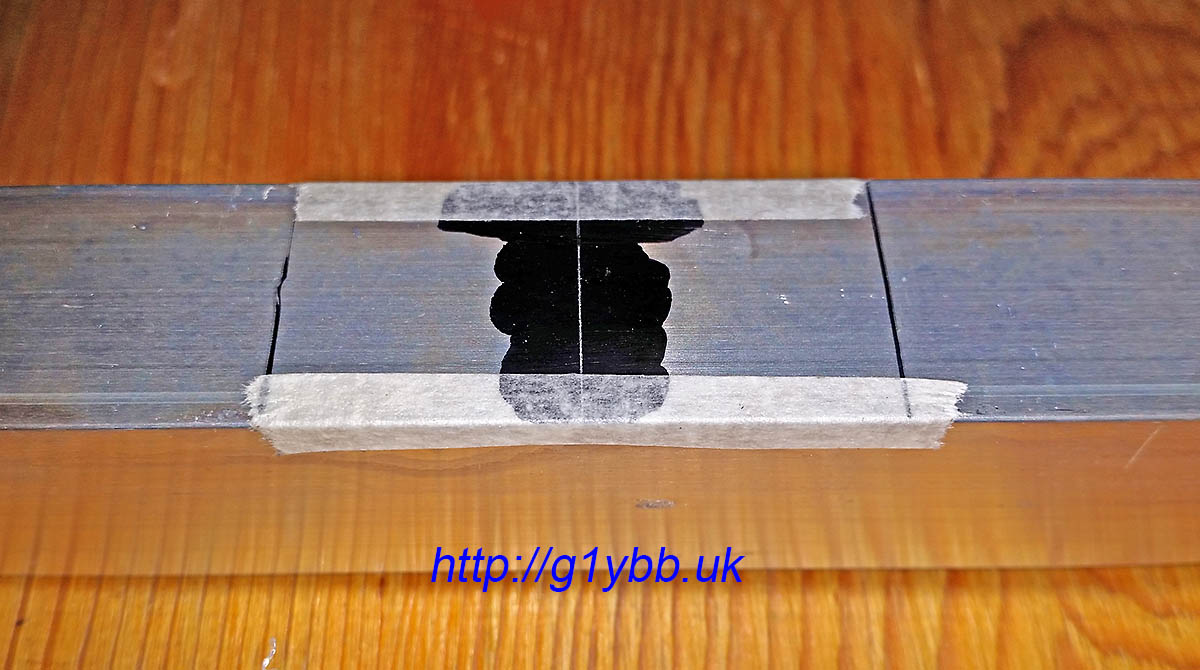
As before I used a section of boom to tame the curling of the coax to allow accurate measurement and cutting of the lengths:
One end of the match fitted:
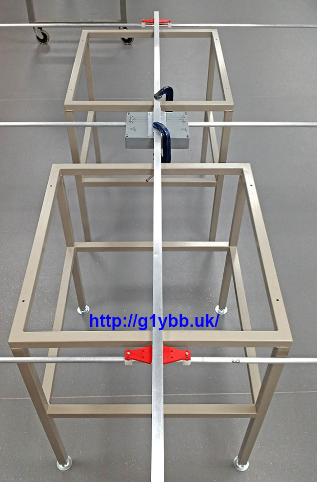
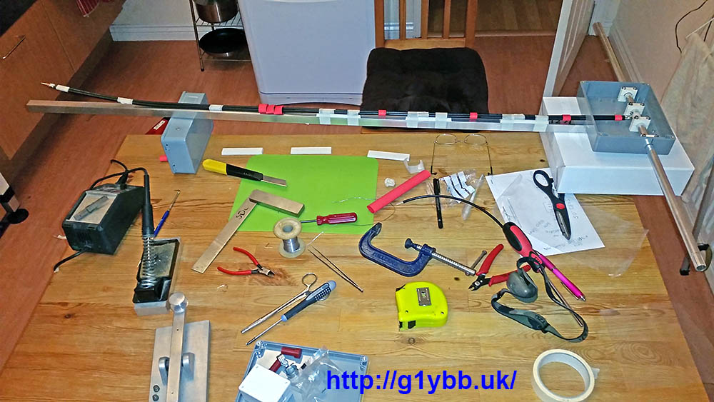
A picture of the process in operation in the ‘workshop’:
Other end of the DK7ZB match completed:
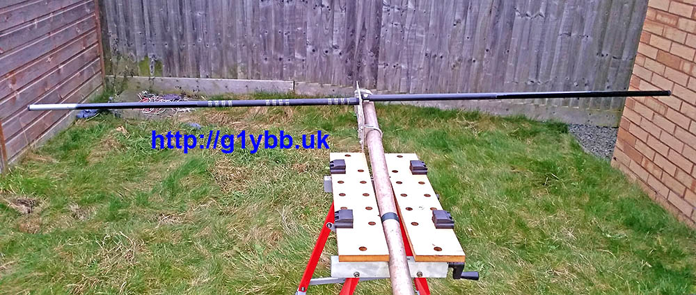
Apart from the bracing the antenna is pretty much complete except for the fact that the element mounting plates are not really man enough for 3 metre long 12mm elements. They were designed for the 144MHz yagi and only 1m long 10mm elements, which they are perfect for. With the larger elements this is how they were flexing with gentle persuasion:
A quick chat with Paul and he drew up a two part brace that he could 3D print me and soon they were in the post!They utilise the same holes already in the element plates and wrap underneath adding strength without interfering with the element clips at all. I used M4 nylon screws to add extra fixings without adding extra metal, the only metal nut and bolts holding the element clips on:
After fitting the new bracing parts this is the flex with quite boisterous provocation:
Much better!
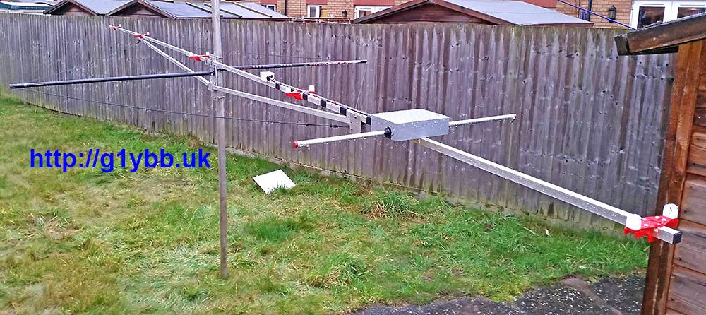
My next consideration is bracing. Long supports were made and fitted utilising the same fittings as on the 144MHz yagi. In fact as I write this I have started work on a 70MHz yagi. All three will fit on the same fittings on the portable mast, and the 70MHz yagi will re-use one of the 144MHz yagi braces and one of the braces for this yagi. The angle of the supports is quite narrow but they do support the boom and keep it straight. This yagi also will need side guys to protect it from the wind. I have several bottom sections of 4m fishing poles left over from HF antenna projects so I utilised two of those. Again Paul quickly produced some parts for me. Some ‘plugs’ to fit to the mast plate to mount the poles onto:
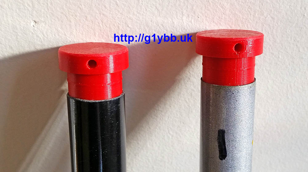
And some stoppers to go in the end of the poles for the 3mm dacron cord, which is very strong and has very little stretch. The stoppers are a good interference fit:
Side guy poles fitted to the mast. These are a friction fit to the ‘stoppers’ and quickly assembled on site:
The sides guys clip onto a plastic bushed (thanks Paul!) bolt on the boom supports with a single karabiner each end. Very quick to deploy:
Next step was to test it! This was done after work on the Wednesday before the first 50MHz UKAC in Jan 2017 the following day! It was reading 1:15 throughout the SSB portion of the band, which was slightly disappointing. There was no time to look into this as I needed to get back home (testing was done in a mountain’s car park) and pack for the next night’s contest!
On the night of the contest the in radio SWR reading was quite low so I was happy the radio was feeling OK about the match and used the new antenna for the first 50MHz contest I have done in 20 years. The yagi seemed to work pretty good and I even managed to beat G4CLA in the AR section of the RSGB 50MHz UKAC January 2017, which I was delighted with!
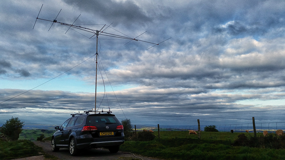
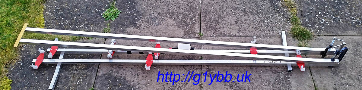
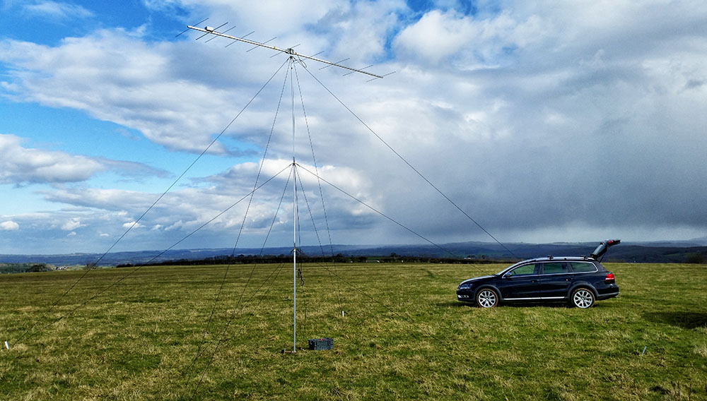
Here is the beam on my portable setup. Longer than the mast is…
I was scrolling down my Facebook feed and spotted a post in I think one of the SOTA Facebook groups mentioning a BX-184 CQ Parrot. It looked interesting at first, then awesome! Within 20 minutes I had it ordered.
This is a modification to the standard MH-31 microphone that comes with the FT-817, FT-857D and FT-879D etc. It will record and playback a message, perfect for calling CQ Contest or CQ SOTA etc, but without the requirement to carry and connect up another gadget as it fits completely inside the microphone body. It was designed by Oliver DH8BQA and he describes it on his website here http://www.dh8bqa.de/bx-184/.
It is available for sale on the German Funk Amateur site here Funk Amateur BX-184. However they also do another kit that includes an MH-31 microphone body if you don’t want to disturb your original mic and that is the option that I took Funk Amateur BX-184M. The website is all in German so if like me you don’t speak German Google Translate will help a lot! There is also now a USA vendor here http://www.box73.com/product/2
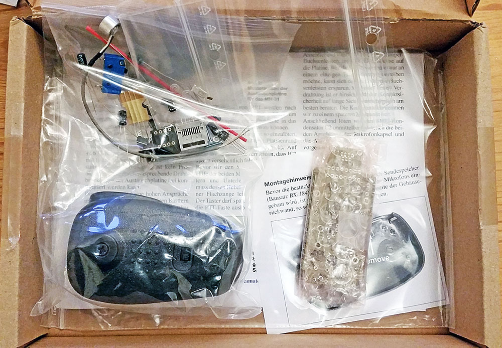
It came pretty quickly and this is what you get in the box:
A complete kit with all you need. The PCB is part SMT (surface mount technology) and part through hole components. You just need to fit the through hole components.
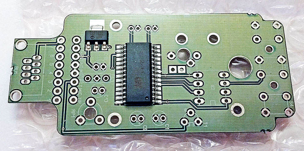
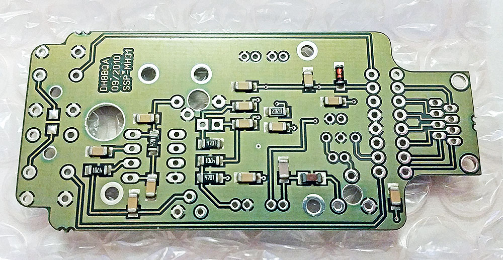
The double sided PTH PCB is very nicely built.
Top:
Bottom:
Before it arrived I did some research and found some mods made by DG2IAQ on eHam which sounded worthwhile:
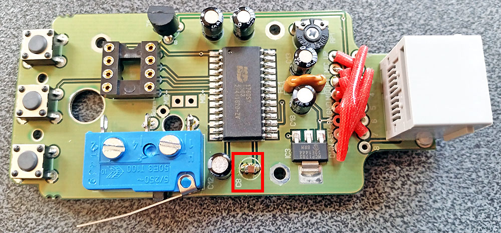
Mod 1:
“I do always replace C8 (4,7µF) by a nonpolarised SMD 1,0µF to fasten up the AGC. With this Change the internal AGC works more as a mic compressor than as a (slightly delayed) mic Level limiter.”
Mod 2:
“And for the first time I changed R4 (82k) into 56k to bring the sample rate from 8kHz up to 12kHz (by a shortened play time of 40s instead of 60s, but that’s still more than enough for my needs). This change gives even more punch for the replayed calls as the sound is a little more high-pitched afterwards. You simply can solder a 100k SMD in parallel to R4 instead of completely replacing it.”
I emailed Oliver DH8BQA for his thoughts on these mods and he confirmed they should be worthwhile.
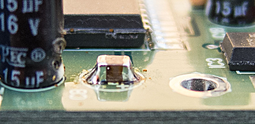
So I decided an 0805 ceramic chip 1µF capacitor would fit best across the pads for the 4.7µF electrolytic it was replacing:
I should have fitted this first as the 15µF cap next to it made it awkward to get a good solder joint on the GND side of the capacitor due to the ground plane wicking the heat away. Got there in the end though:
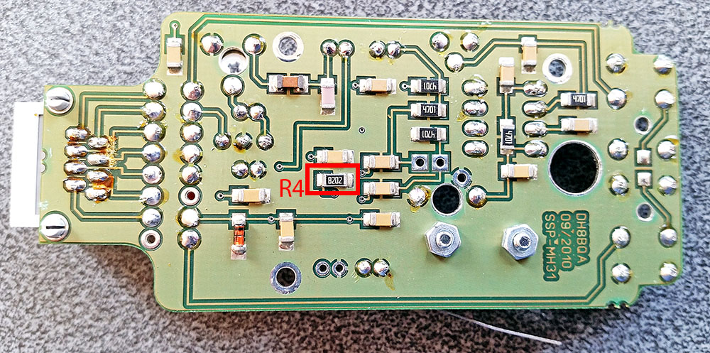
R4 is an 82K 1206 sized resistor located on the rear of the PCB (this is easy to locate as the kit comes with build instructions in German with a good circuit and layout supplied. English instructions can be downloaded here, page 5 onwards English Build Guide):
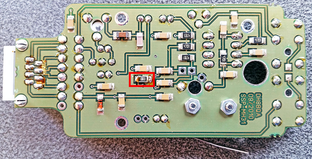
And with a 100K 1206 fitted in parallel (on top of the fitted resistor) as suggested above:
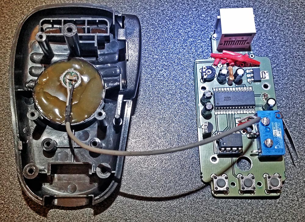
With all parts now fitted (including a 1206 capacitor fitted across the supplied electret insert terminals) all that is left to do is mount the electret insert into the microphone body and solder that to the PCB.
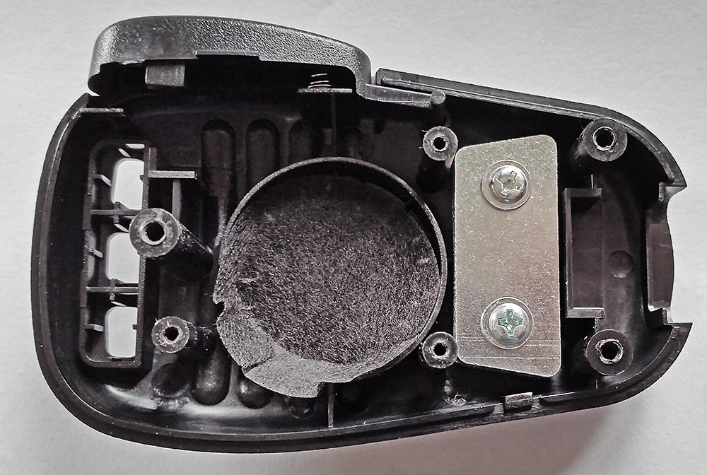
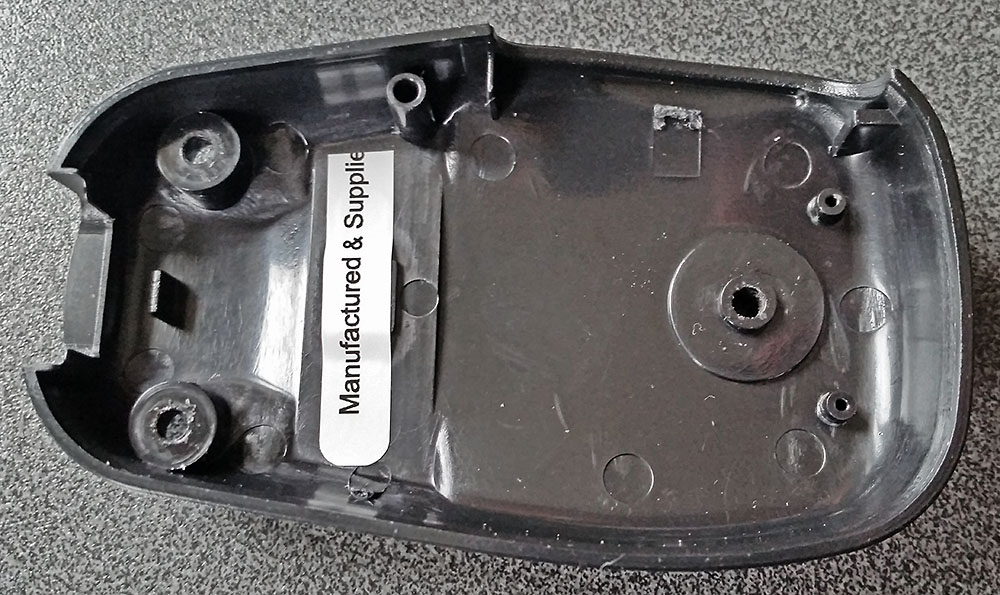
Opening up the supplied microphone and removing the PCB revealed these 2 slabs of steel in the body. The only function of these I could see was to add weight to make it feel more substantial. So I got rid of those. No point in carrying dead weight:
Next I hot melt glued the electret insert into the mic and filled up the void as the instructions said. Actually I filled more than the picture in the build instructions showed by mistake. Then solder the screened cable to the PCB and fit the IC and it’s ready to be assembled:
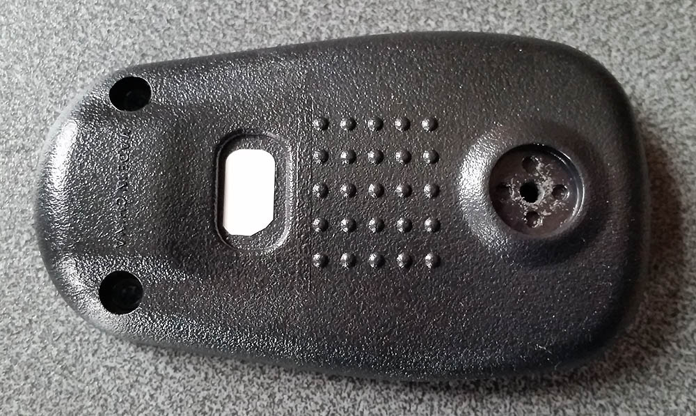
As the replacement PCB does not have the two position slide switch, there is the unused hole in the back of the mic. For this I just used some good quality sticky label material I have to hand.
One piece inside:
And one on the outside.(not pretty but functional):
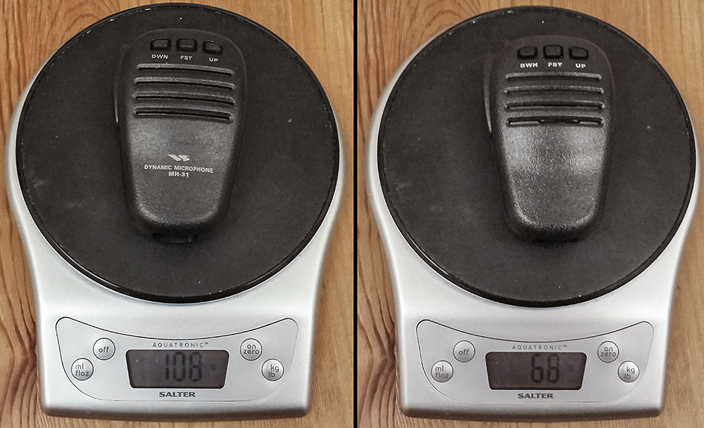
Once assembled I compared the standard supplied Yaesu MH-31 mic for weight against the BX-184 CQ parrot. A 40% saving in weight, I’ll take that:
I soon connected it up to the radio ready to go but there was no outgoing audio! What!? With several projects on the go I could do without time spent fault finding. What if I have cooked the electret soldering the capacitor on now it’s well and truly hot glued into place. Hmmm. Hold on, what was that pot trimmer for? I remembered when building it I couldn’t see any mention of it. A check of the circuit confirmed the obvious answer. It’s on the mic output to the radio. A quick check with the meter confirmed it was currently set to ground the mic line going to the radio. A quick tweak and we are back in business.
In fact the worst part was setting up to monitor myself. Eventually I had a reasonable system, FT-857D on 5Watts into a dummy load near the FT-897D with a 4mm banana plus as an antenna feeding into the sound card on the PC, with Audacity dealing with the recording. The recordings are not broadcast quality but are good enough for a comparison.
Here is a CQ call using the standard MH-31 mic:
Here is same CQ call live using the BX-184:
And the replayed recorded CQ call from the BX-184:
I might need some on air radio reports for final setting but it doesn’t seem to be clipping at all though does have a little more punch.
Can’t wait to try this out in a contest or SOTA activation. All in a great little kit well thought out and went together very well. The only small point is no actual mention of the trimmer function or setting which would be good as a reminder if nothing else. I know this kit is aimed at radio amateurs who should be able to look at the circuit and deduce why the pot is there so this is a very minor point in a great kit.
Edit:
I have since used this ‘in anger’ in 144MHz contests. The first contest I got some complaints about over driving and being wide (complainant was also wide to me for that matter!!). But I turned SSB mic gain down in the FT-817 and back at home I did turn down the audio output level on the microphone itself and did some tests between it and the standard MH-31. Subsequent contests have resulted in zero complaints but some good audio reports.
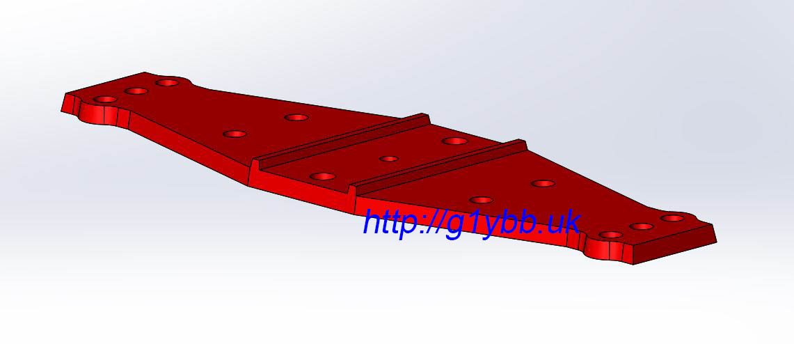
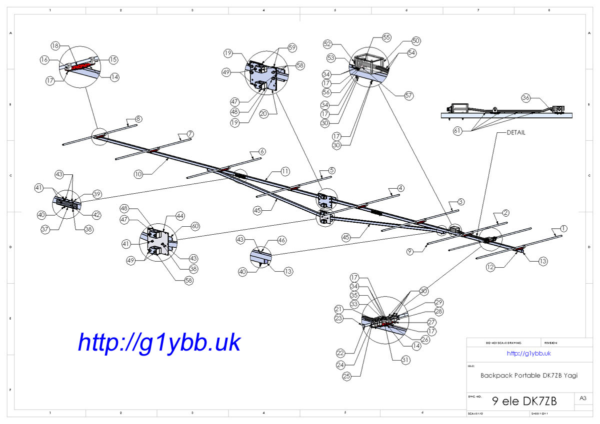
In order to facilitate the building of my backpacking lightweight 144MHz 9 element DK7ZB yagi with a friend I came up with this reinforced plastic element mounting plate.
The primary idea behind it was that it would make it easy to accurately position elements in the right position along the boom and also ensure the elements were mounted nicely perpendicular to the boom. This was the sought after benefit for my build, ensuring all elements were nicely parallel to each other and in the same H plane. Also it would allow easy use of specific element mounting methods particular to my variation of a DK7ZB 144MHz long yagi beam design. The mounting plate is specifically designed to work with 20mm square section boom.
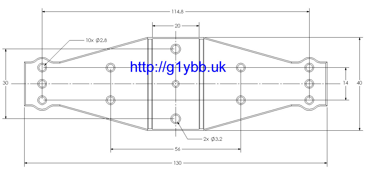
Here is the 3D design of the element mounting plate: And a dimensional drawing for suitability to other yagi build applications:
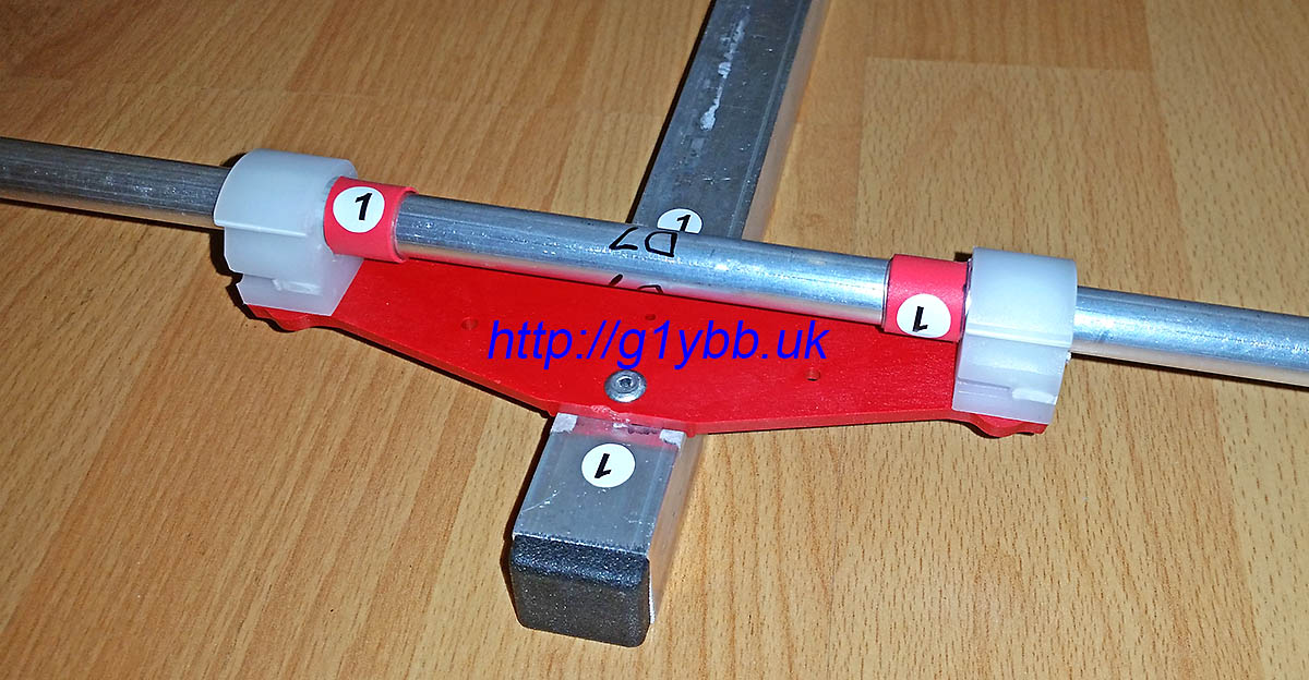
For my beam (linked at top) I was able to use this to mount both parasitic elements and the custom driven element:
The element mount plate has location ridges underneath to align perpendicular with the 20mm square boom and has a small central sighting hole to align with a marked up boom for element centreline positions:
Two fixing holes are provided to fix the element mounting plate to the boom. They are sized for 3.2mm pop rivets but can be easily drilled out for other sized bolts or rivets. The element mounting clip holes provided can also be easily enlarged. They are supplied undersize for M3 deliberately so that an M3 bolt has to be screwed into them thus providing a precision centre aligning of the bolt and hence element clip mount.
Here is a video of the element mounting plates in action:
As I was planning to resume 144MHz contesting but this time full backpacking style I wanted a decent beam that was suited for repeatedly assembling and disassembling. I have a Cushcraft Boomer and also a pair of homebrew DJ9BV yagis but neither are really ideal for the job. After nearly two decades away from radio yagis have moved on and researched showed the DK7ZB yagis were very popular. His designs seemed ideal for my purpose.
I settled on the 9 element long yagi as it is not too long but with decent gain and also has a good flat SWR curve. The RSGB Backpackers section we wanted to participate in only allows one antenna so stacking shorter yagis was out.
The dimensions are available on Martin DK7ZB’s site:
I went for the 10mm elements as a compromise between size and weight and best performance. I was also able to find 10mm clips to suit my intended design.
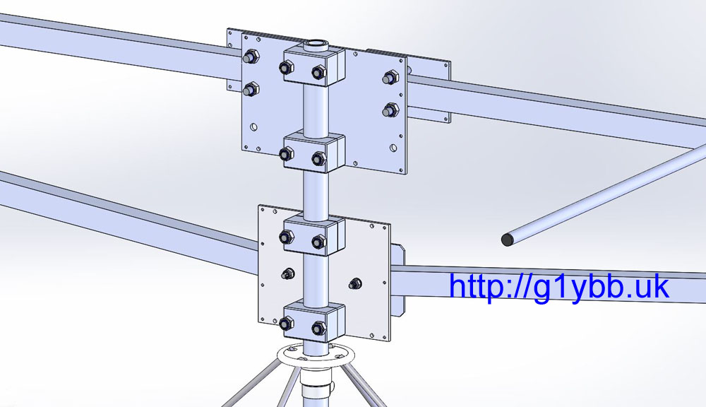
You can buy some of the DK7ZB yagis ready made and also in kit form, but I didn’t really think the parasitic element mounting methods were ideal for repeated building especially in cold weather. Also the driven element was a problem as it’s not ideal at all for disassembly. There was one example of a driven element designed for taking apart on DK7ZB’s site but I couldn’t find any parts like they were using. I was already building my own lightweight portable mast so I decided I may as well design the yagi from scratch too. So I modelled the full antenna down to every nut and bolt in 3D CAD software. This enables me to know exactly what materials I need and also predict pretty accurately the weight, bearing in mind I plan to backpack this up hills:
To source the main raw materials I found that it was cheaper to buy from https://shop.nuxcom.de/ in Germany than anywhere I could find in the UK! I went for the 20mm square boom and 10mm elements. My 3D CAD model told me I wanted two sections of boom 1.72m long and one section 1.62m long. (After ordering I noticed that is the same lengths Attila uses in his 9 element kits!) I didn’t go for a kit as there were several parts in the kit I didn’t need and I wanted to order a few spares of the elements just in case I cocked up some of the cutting. Nuxcom sell the boom in 1.5m and 2.0m lengths but the 2.0m lengths cost more than double the shipping, so I asked Attila if it was possible to buy 2.0m lengths but have them shipped in two pieces, 1.72m and 28 cm lengths. He did this for me at no extra cost which is good service. The offcuts would be useful for doing tests later.
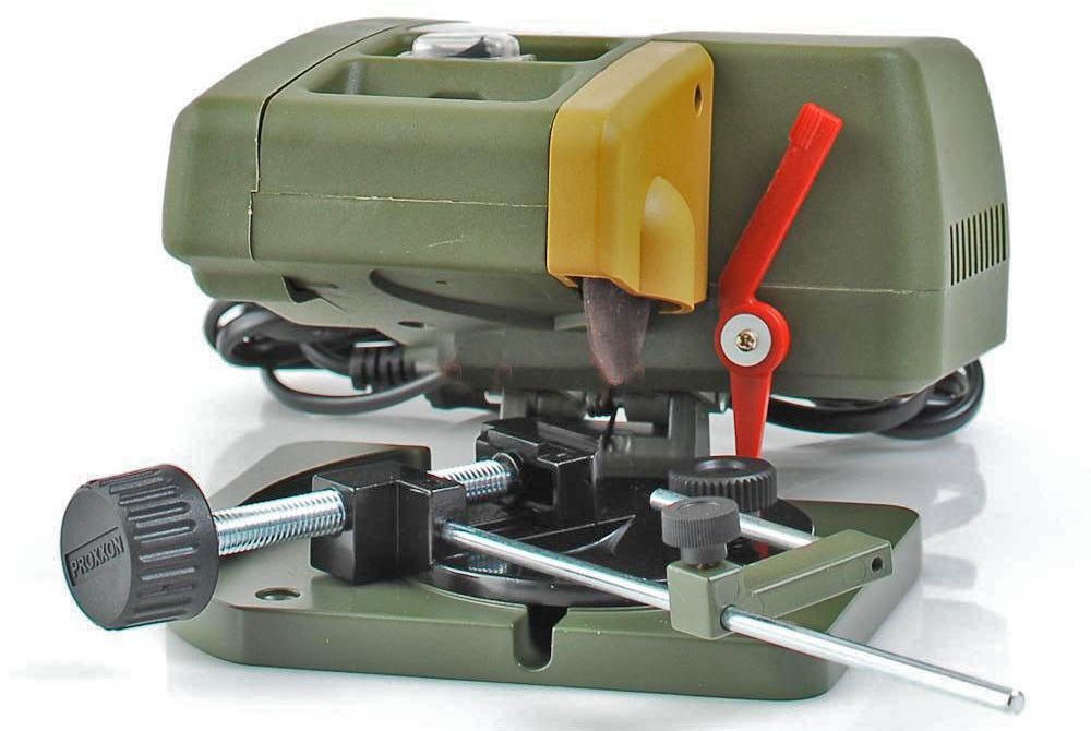
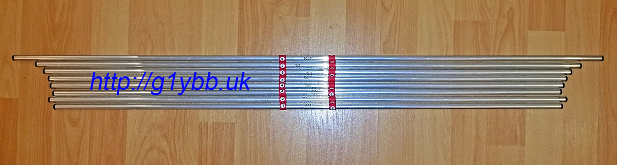
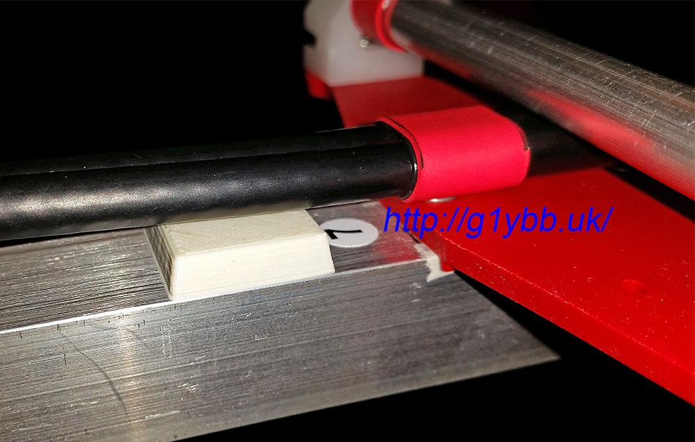
First building task was to cut the parasitic elements to size. Although I’m pretty good with a wood saw I’m a bit rubbish with a hacksaw and I didn’t want to use a pipe cutter as certainly for the driven element I needed no deformed ends to the tube, so I managed to borrow a mini circular disk cutter like so:
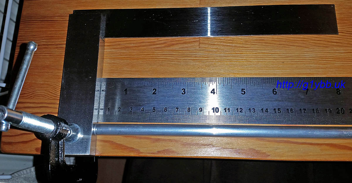
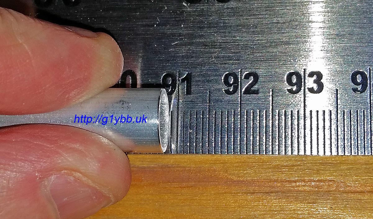
With this I was able to make nice square cuts. To measure them I used a metre ruler (tape measure for the reflector-checked against the metre rule first) butting both up against a stop to get an accurate measurement. I checked that the first mm was a true mm before starting as some rulers have a dubious first mm:
And checking D2 (ever so slightly short if anything by a fraction of a mm):
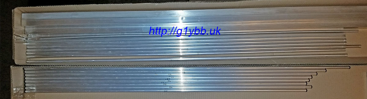
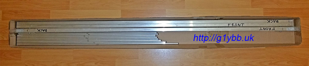
After cutting the parasitic set I fitted end plugs from Nuxcom for a nice finish. (Elements in bottom box, spare elements and boom sections in top):
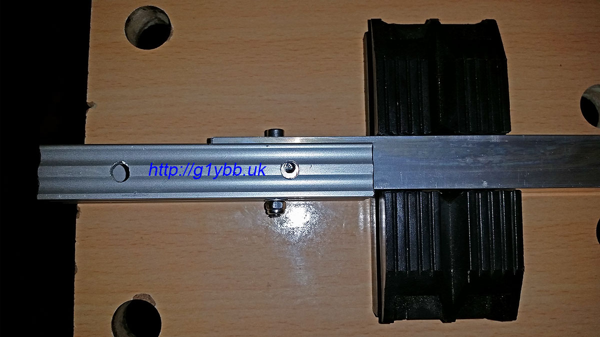
Next to assemble the boom. I bought the Nuxcom boom joiners and I must say they are very well recommended. The fit onto the 20mm boom sections is a snug push fit and the extrusion is thick enough to be strong yet still light. I got them with the M4 bolt and wing nuts. The one thing I didn’t like so much was the massive hole for M4 which was 6.5mm diameter. However, once I modelled up the joiners and dropped them into the antenna assembly I could see that a 4mm hole at the top of the 6.5mm hole would be pretty much bang on centre of the boom, and mean the boom could not move up in the joiner. I also added a vertical bolt on each side of the joiner too as shown below. That meant the boom section was forced into the joiner tightly ready to drill the holes. I drilled from each side, using the 6.5mm hole as a stop for the 4.0mm drill bit:
The above picture is showing the boom joiner fitted to the centre section. Both joiners are fitted to the centre section and will stay there permanently so I have used socket cap heads and nylocs, all stainless steel, bolts cut to minimum length. (The four supplied wing nut bolts will be used to attach the end sections on the hill top). With both joiners fitted, the centre section then is pretty much the same length as the outer sections (by design). I also bought the square boom end caps from Nuxcom to finish them off nicely:
The boom was then assembled in my hallway and the centrelines of the element positions scribed on. I used a tape measure masking taped to the boom to ensure it never moved and starting at the 100mm mark on the tape measure to eradicate any errors from the tape measure hook end.
The element clips I needed to find something that was quick to mount the elements and remove them again. The typical single bolt through the centre of the elements I didn’t fancy as it was a bit fiddly especially with cold hands on a windy hill top. My friend found these 10mm pipe clips that were ideal. Snap in and lock, and easy to open again to remove the elements. They will have a finite life but my test piece has had dozens of cycles and they come in a bag of 100 for under £6: Another plus point of this is the element centre is a reasonable distance off the mounting surface which means I had good scope for getting the driven element to be on the same plane as the parasitic elements. I just need some suitable plates to mount these on nice and squarely on the boom. My friend offered to injection mould me some rather than my trying to accurately drill out several plates exactly. So I modelled up a mounting plate to be made from glass fibre reinforced nylon which is extremely strong and stiff for its weight. The image shows the underside. The two ridges are to locate on the square boom:
Soon in the post came a parcel of element mounting plates. We decided riveting them on was a secure and lightweight fixing method. The two location ridges on the bottom had a slight amount of play when offered to the 20mm boom which of course would be amplified by the approx 100cm elements so I fitted two tiny strips of masking tape which made the plates a perfect fit. Once the rivets were in it doesn’t matter if the masking tape decomposes away:
The small hole in the very centre of the element plate is a sighting hole to align the element in it’s correct position on the boom. This was used to line up to clamp the plate on for the drill of the first rivet hole:
Once the first rivet was fixed, the clamp was no longer needed and the 2nd hole drilled and riveted:
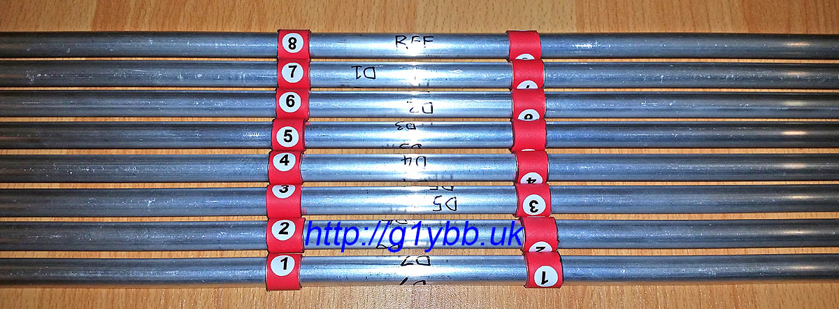
Then a simple case of fitting the 10mm pipe clips and snapping in the elements in the right place centred on the boom. In order to easily locate the element centrally on the boom with out any time consuming I fitted to each element a piece of adhesive lined heatshrink to be positioned between the clamps. I also added some marking numbers for the 8 parasitic elements, numbered 1 to 8 from from to reflector:
Now the easy bits are done, time for the driven element. This was the biggest head scratcher on how to make it suitable for repeatedly taking apart and assembling. I needed to come up with a method that both left the electrical connections to the driven element halves but also enabled me to remove them for transportation. This meant a split in each half of the driven, but how to attach it?
I decided to come up with a system of employing a ferrule in the driven to join the two halves. With some custom made parts it would also be mounted on the same element mounting plate as the parasitic elements and is the reason the element plate is larger than a typical one, although that was also good for rigidity and build accuracy.
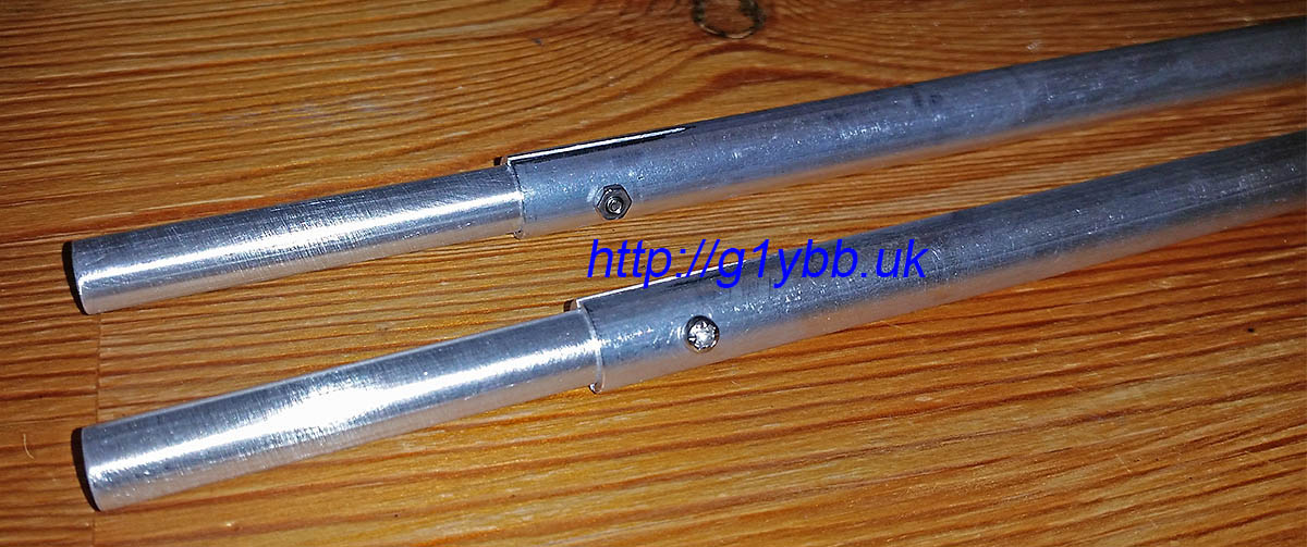
When I ordered my 10mm element tubing from Nuxcom I also ordered 1 metre of 8mm tubing to do this. But there were two issues with this. The first was this was the only piece of tubing that arrived with a bend in it. If I had planned to use it as an element I would have had to reject it. As it was I could cut out straight parts to use but the 10mm diameter 1mm wall thickness elements have a bore of about 7.92mm and the 8mm tube an outer diameter of about 8.10mm. No chance of a fit. Out with the calculator and it soon transpired 5/16″ should be a perfect size. I bought some T6 grade aluminium from eBay and it was a perfect fit. Sliding with no slop at all.
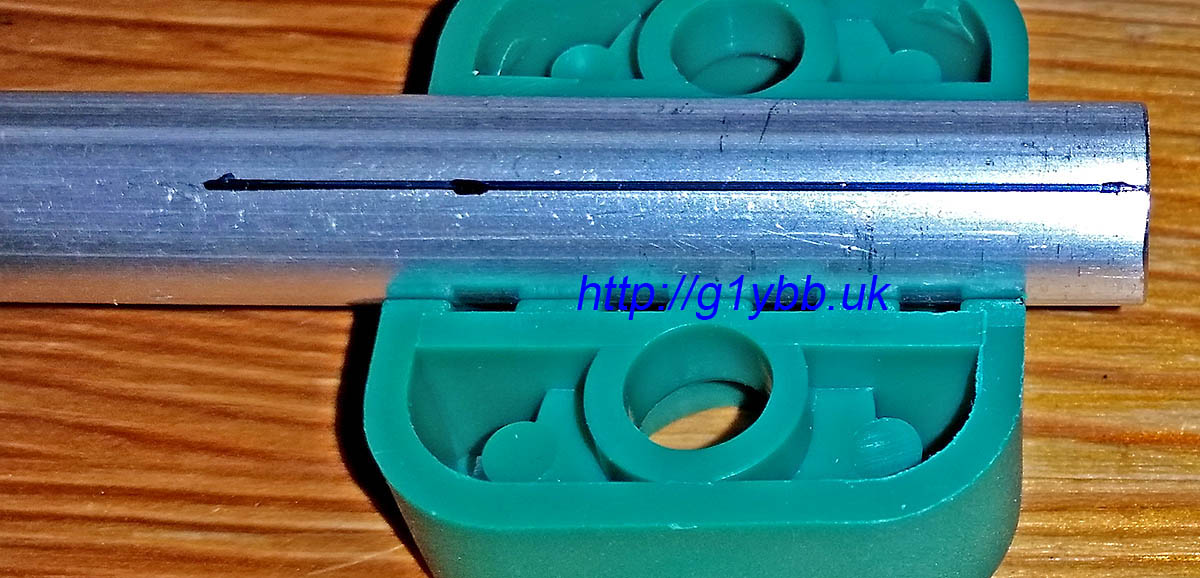
To cut slits in the 10mm tube to compress it with clamps to grip the ferrules I used two 10mm element clamps to mark a dot each end and each side of the clamp and joined them up to make cut lines to follow:
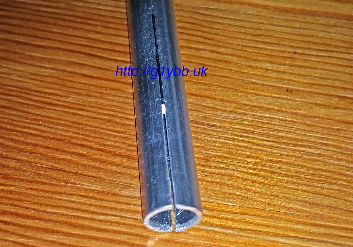
I’m not fantastic with a hacksaw to be honest but using the element clamps above to hold the tube in the vice I was able to cut (from both sides) fairly neat slits with a junior hacksaw (I wanted thin slits):
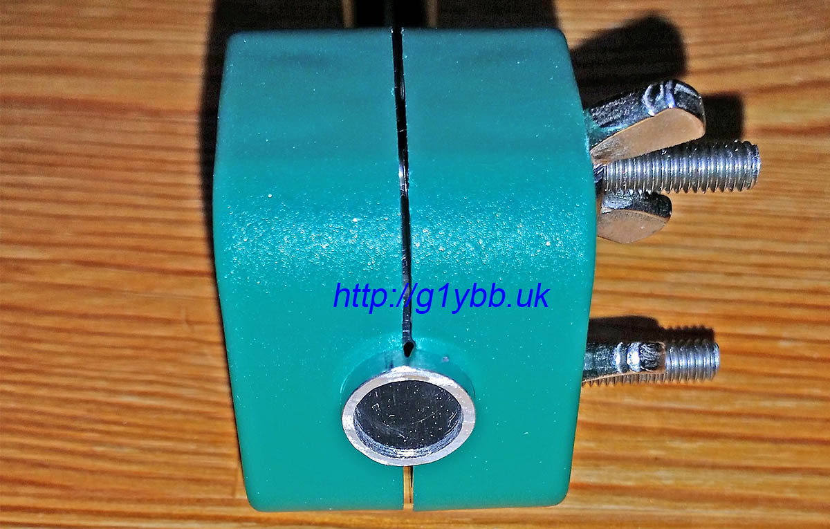
Then it was a case of fitting the ferrules into the outer halves of the driven elements and adding a screw to maintain a good mechanical and electrical grip:
Next to feed that driven element. I decided to straighten out the feed match to take the feed point a little closer to the centre of the yagi. I’m using WF100 75ohm coax which is fairly low loss for its size, and is not too big or heavy. Its claimed velocity factor is 0.85 so I worked out the length as so:
300/144.300 = 2.079m full wavelength
2079/4 = 519.75mm for quarter wave
519.75 x 0.85 = 442mm
DK7ZB gives a length of 440mm for this velocity factor, but I notice all his lengths are in multiples of 5mm so I wondered if he did some rounding down? I hope so!
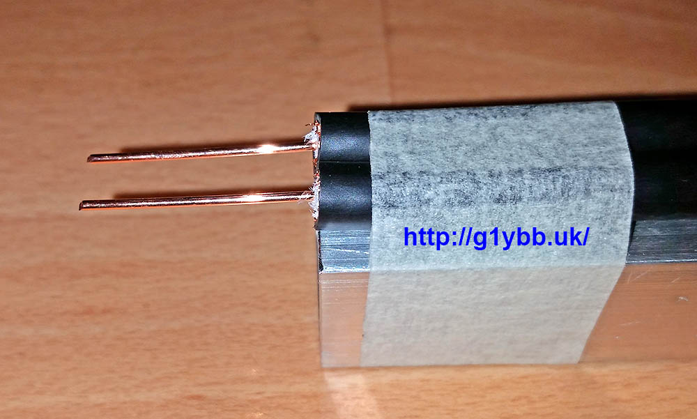
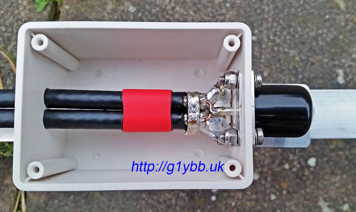
This is the length of the braid. I hate stripping and cabling up coax so did all I could to avoid twisting bits of braid about. I cut the braid and dielectric off square and about 5mm or so of the outer jacket to reveal the braid. With a very large tipped iron of unknown wattage I was able to tin the braid nicely with no apparent melting of the foam dielectric. I then made a small tinned copper plate to bolt to the N-type socket and solder to the braids making a good earth. For good measure I added a loop of braid from some RG223 soldered all round. Then made the inners as short as I could and soldered to the N-type:
To tame the annoying curling coax I found yet another good use for the short boom offcuts I asked Attila to include. I taped the coax out straight to measure the 442mm finished length:
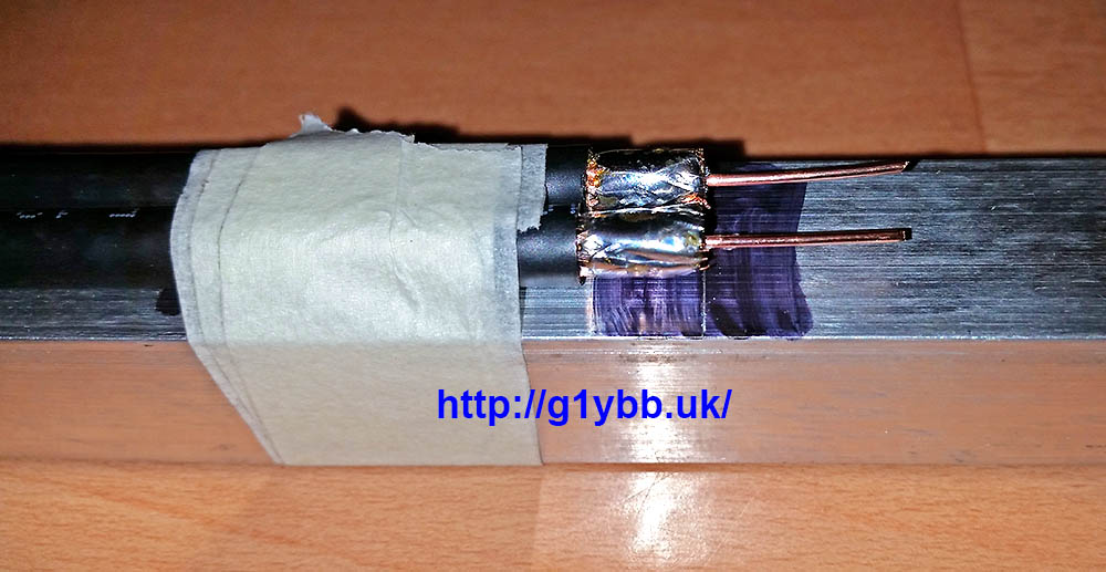
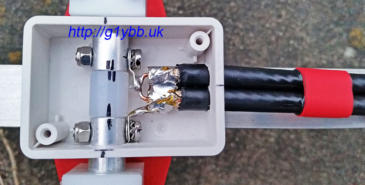
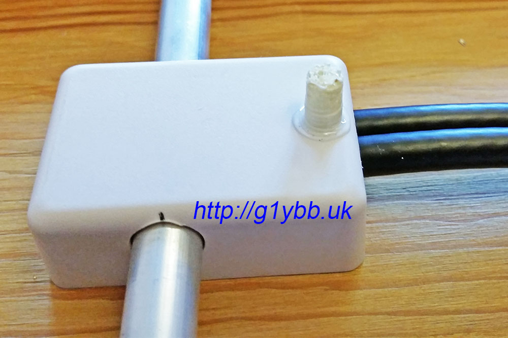
You can see I am using red adhesive lined heatshrink to keep the coaxes tidy and together. In the picture above the tiny box for the driven element connections is threaded on ready for the stripping and fitting of connections. I used a similar method as on the feed end with some copper sheet to join the braids and solder tags to connect to the element halves. This was a very fiddly job but hopefully worth it keeping the connections as short as I could manage:
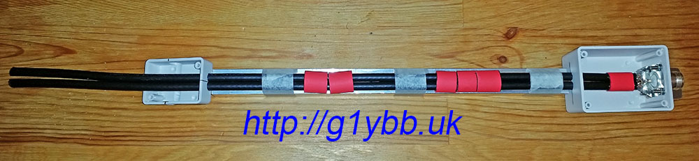
To support and space the feed off the boom as recommended by DK7ZB (although this is going to be used for QRP almost exclusively) I got some ABS spacers 3D printed which I placed in position and then wrapped tightly with insulation tape. The idea is to keep the coax off the boom (which it is miles away from) but also as far away as possible from the element plate rivets but also as far from the element the coax passes under:
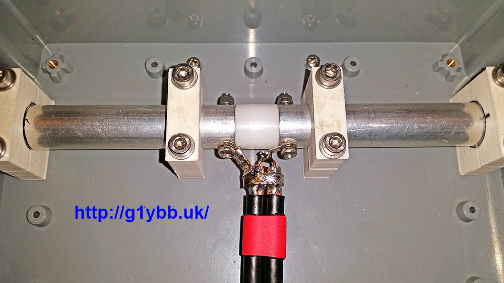
The driven element box is supported solely by the driven element inner pieces themselves, but I added a very small 3D printed pillar to make everything secure:
Here is the feed match finished:
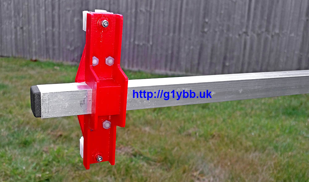
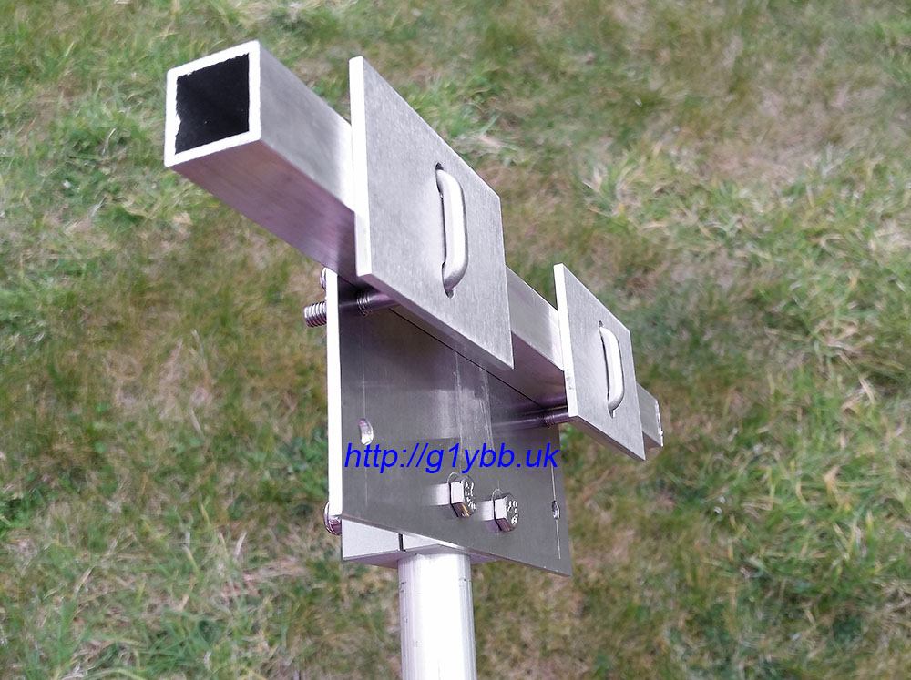
As I plan to use this on a lightweight mast section only 20mm in diameter I didn’t think the usual U-bolt clamps would be able to create enough friction to stop the beam spinning on the mast without being so tight to possibly crush or weaken the 20mm ali mast. I bought some plastic 20mm clamps for large yagi elements from Nuxcom to try but they do not have enough friction. So I drew up some half round clamps to be made out of aluminium:
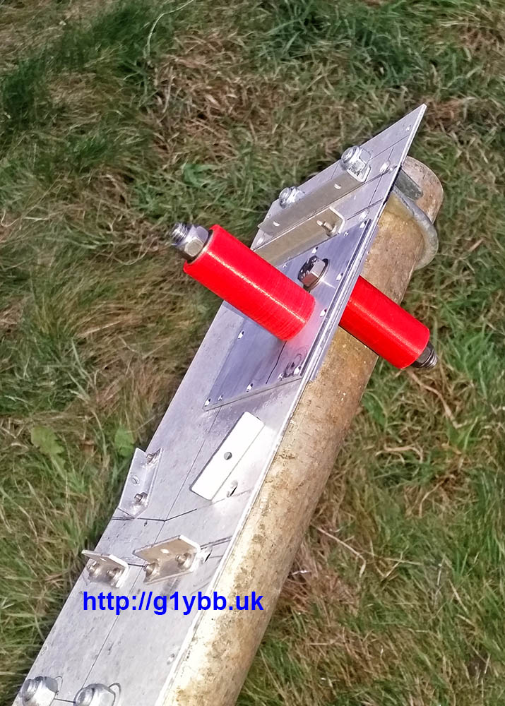
I used a small 3mm aluminium plate in usual manner and bought some 20mm square U-bolts for the 20mm boom itself. As the 20mm boom again is quite small for a long yagi I was again concerned about over tightening the U bolts and creating a weak and potential failure point so I added some small 3mm aluminium plates to allow it to be tightened up nice and tight without any fear of crushing the boom. Here is the finished boom to mast mount. (The two unused holes visible are there to use with the lower 20mm boom mounting holes for a 25mm boom yagi I have):
I used a similar arrangement for the boom support to mast fixings, the aluminium clamps and a slightly smaller aluminium plate. Just a simple M4 bolt per half of the boom support and another plate to help strengthen it all up. The intention is that the boom supports will also help offer a little sideways strength against the wind as well.
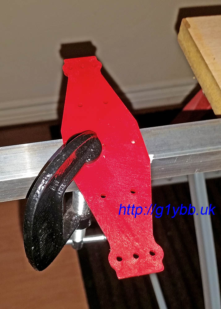
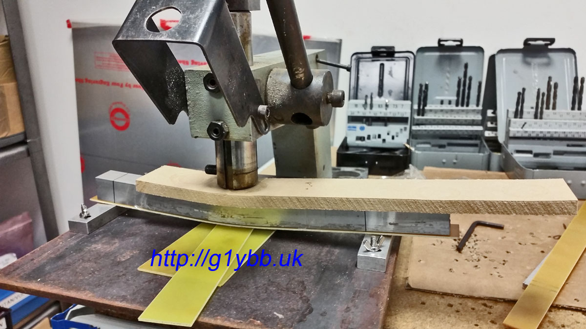
To bend up the boom supports I first tried to bend some 20mm square section (same as the boom) in my workbench jaws (seen above in the first picture after cutting the elements). They were not strong enough to bend it! Note this is not a proper vice as such, more of a drilling and cutting bench with jaws. I then thought I might use a bottle jack to apply the force but couldn’t think of anything solid I could jack onto. Then I remembered we have a small 3000lb lever press at work used for punching small holes in sheet metal. I soon made up a jig using a 10 inch square of ¼” steel with some small aluminium blocks and I used the spare offcuts (yet again) to work out the right amount of packers below the centre to give me the bend angle I needed:
I used 10mm MDF to spread the load from the press and protect the 20mm square tube and a strip of bare FR4 as a bearing and protection to the underside. Once tests were done I quickly and easily put the bends in the actual supports:
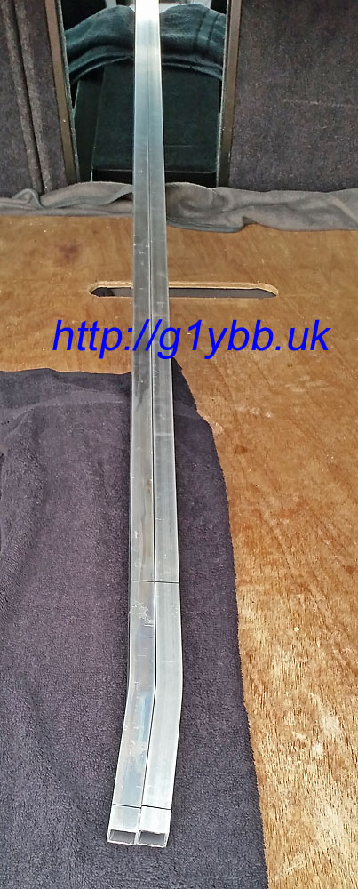
Checking the bends are matched:
Then just a case of offering them up, drilling holes in the right places and fitting. Finished!
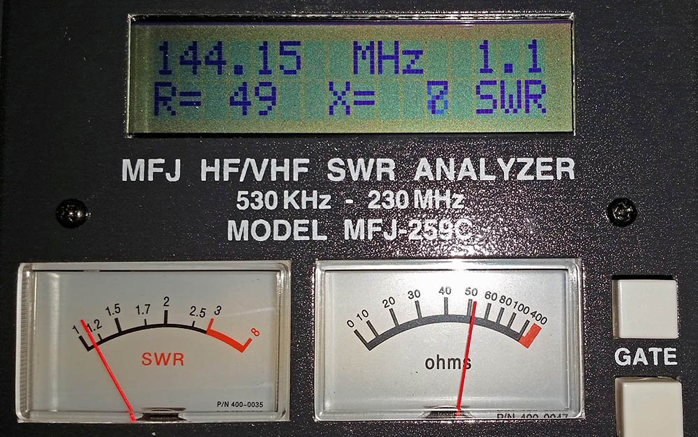
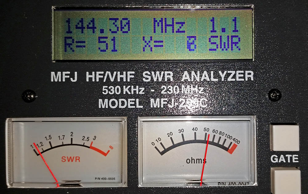
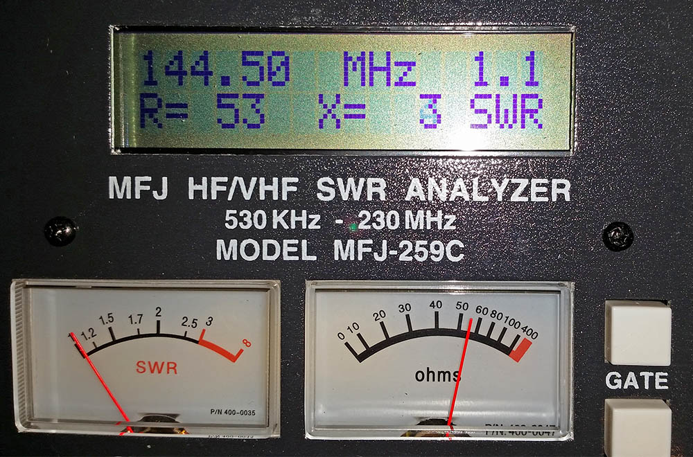
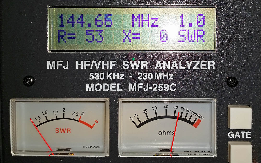
Now for the moment of truth, how does it measure on the antenna analyser? Well to me it looks to be best match at 144.660MHz but is showing SWR of 1.1:1 and 51Ω at 144.300MHz so I’ll take that thanks:
Here is a real time video showing how long it takes to assemble the elements (I have not shown the boom assembly as nothing unusual or new about the boom assembly):
Only job left now is to take this up a mountain top and do some contesting!
Edit: I have done my first contests with this now and it seems to work really well and I got good reports all round. Even with a low loss feeder the radio was not indicating any SWR reading at all on transit. I have come 2nd and 1st in the low power section of the first two UKAC contests I have entered so I am really pleased with the way this yagi performs. It ‘feels’ even as good or better than our 2x 19 element MET yagi array.
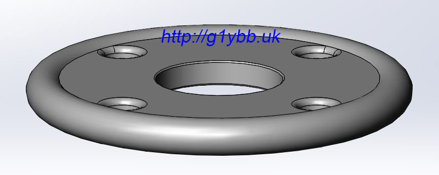
When I made my lightweight aluminium portable contest mast I designed up an ultralight strong mast guying ring to use that was both strong and light. I designed it for my friend to injection mould in a fibreglass reinforced plastic that is really strong. The material is so strong I could not damage a 1.5mm thick long credit card size sample by hand even across the edge of a table. All I did was hurt my hands.
So with one eye on weight and one on strength this is the design I came up with. The design criteria was that these rings would hold up a mast carrying a decent sized 144MHz long yagi with at least a 5m boom on an exposed mountain summit in winds at least as strong as the tent will take but also be nice and light and small. They are very similar to many others you will see (there’s only so many ways a guy ring can be designed), but this is only 61.5mm outer diameter and 14.2 grams in weight:
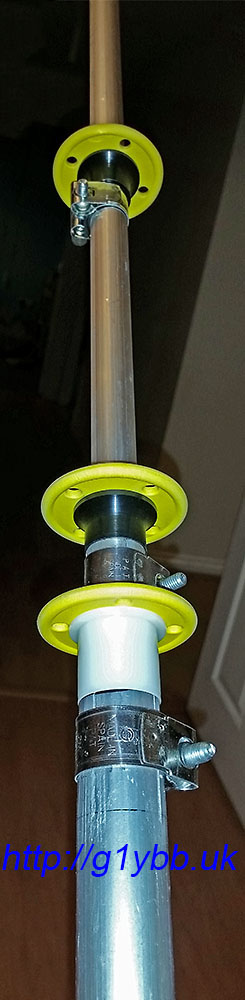
I went for the simple 4 holes rather than extra holes for 3 point guying that some rings offer as it’s easy enough to just use 3 of the holes. Rope holes are 5.8mm which is plenty big enough for 550lb paracord or other ropes you would use with a lighter weight mast system. The centre hole is 20.5mm sized to fit the top section of my mast. For the lower thicker section it’s easy to open the centre hole with a step drill, in my case 26mm. 30mm is about as big as I would open it too though to retain full strength.
When the rings arrived in the post the first job was to test it for strength. I figured I would make a good test load. Just needed something to hang off and give it some welly. I am a good 170lbs, probably more with boots and big coat on. The rucksack is full of 2 litre bottles of water, probably a good 30lbs more easy. So about 200lbs bouncing weight on the guy ring. This is on a very short length of paracord. A longer length will absorb more shock like a climbing rope does:
Once I was happy with them fitted to the mast and the guy ropes tied on:
And in action:
These rings will also be very useful for SOTA activations where the very ultralight commercially available rings may be a little brittle without adding a noticeable weight penalty. Used for a fishing pole mast the mast will break long before these rings will!
I mentioned that these could be ideal for other radio hams doing SOTA activations and other portable operations wanting a very strong but lightweight guy ring he has made these available (pretty much any quantity) on his website: https://dura-id.store/product/lightweight-mast-guy-ring
Having just finished making a lightweight aluminium portable antenna mast for backpacking VHF contesting I wasn’t really happy with the initial way we were tying down the guy ropes.
Typically I have tied off guys that don’t have tensioners with several half hitches. These are quick and easy but they are hard to tie tensioned properly and I have lost two 19 element MET yagis, a Yaesu rotator and an aluminium scaffold pole when one guy worked loose on a windy day. I didn’t want to use tensioners on this setup as they can work loose and we are going to be operating from a tent and won’t see any loose guys until too late most likely. Also I’m using for this mast lightweight paracord which is meant to be good to 550lbs breaking strain, but I am wrapping that around fairly sharp edged aluminium angle guy stakes which might create a weak point on the paracord. The mast is not massive and I have 2 sets of main load bearing guys but I want this to stay up on exposed windy Welsh mountain tops.
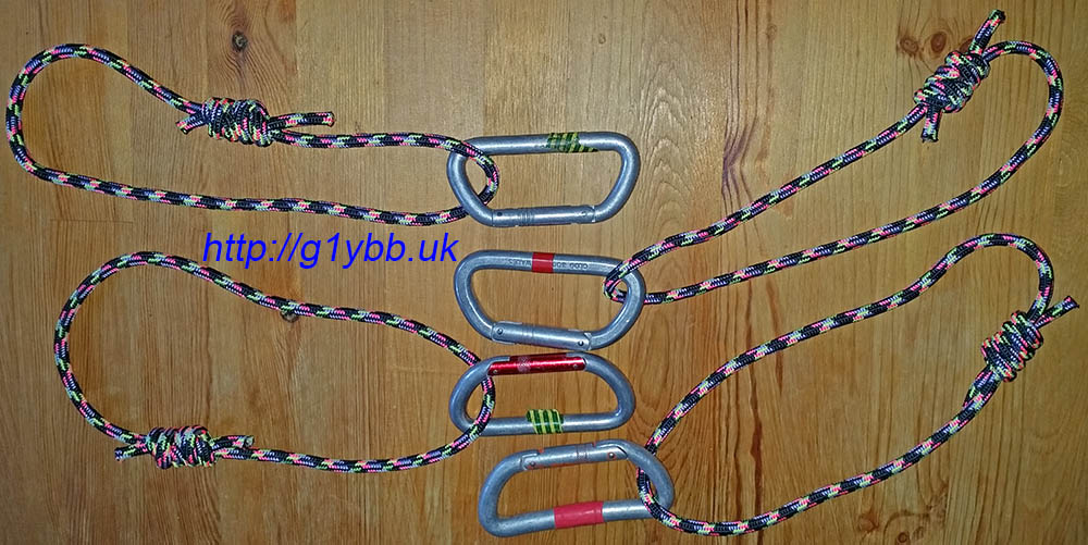
So I thought a round bar would be a better shape to tie the guys to and a clove hitch would be a good start knot as it can be tightened up. For the round bar I thought I would use some of my old climbing karabiners. And to attach those to the guy pegs I would use some small sized climbing rope about 6 or 7mm and use a clove hitch to quickly attach those to the pegs.
Here are the karabiners and rope loops. The rope loops were made from about 1m of rope each and a double fisherman knot used to make the loop:
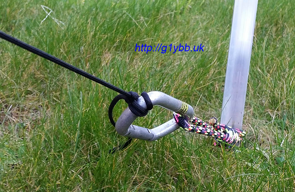
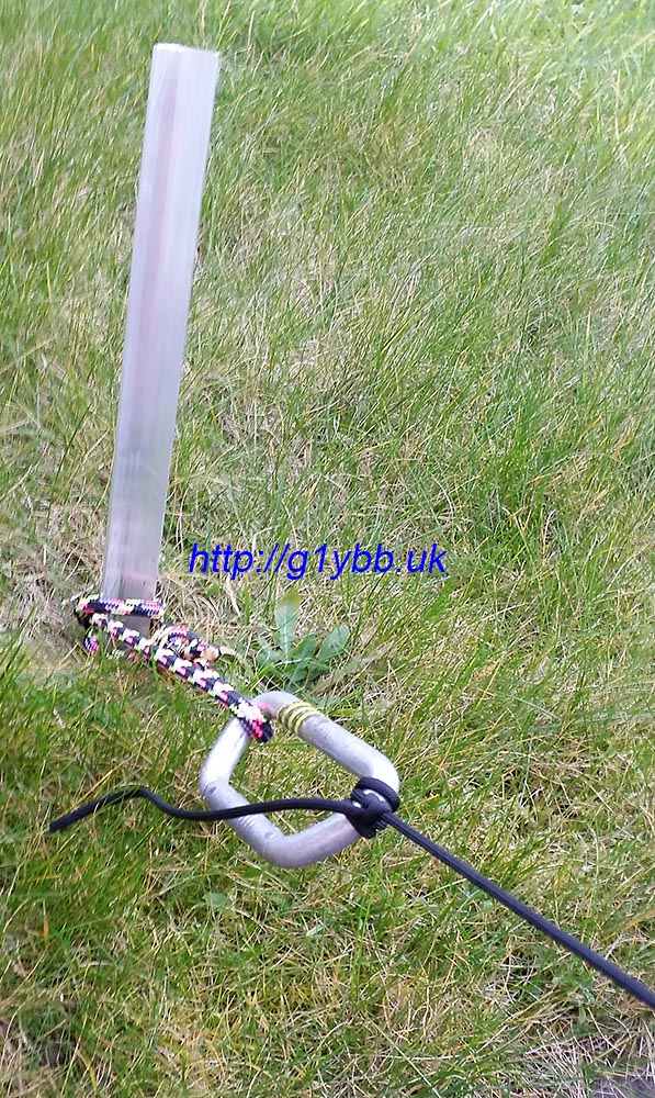
Once the karabiner was fitted to the guy peg it was very quick and easy to make a clove hitch and slip it on, tension, then lock off with a couple of half hitches:
This adds an extra 381grams to carry but I think it will be worth it in the long run. I could probably cut that down with newer smaller and more lightweight climbing karabiners (I’m not going to risk the cheapie ebay style mini ones) and probably a smaller rope would be OK to use:
This is one way of many options, I’d love to hear your methods and tip and tricks!
(email explained on welcome page)
 These plugs were from nuxcom.de but he has ceased trading now but they are available at various places including Tino’ Funkshop but these days if you are in the UK it’s best to look more local.