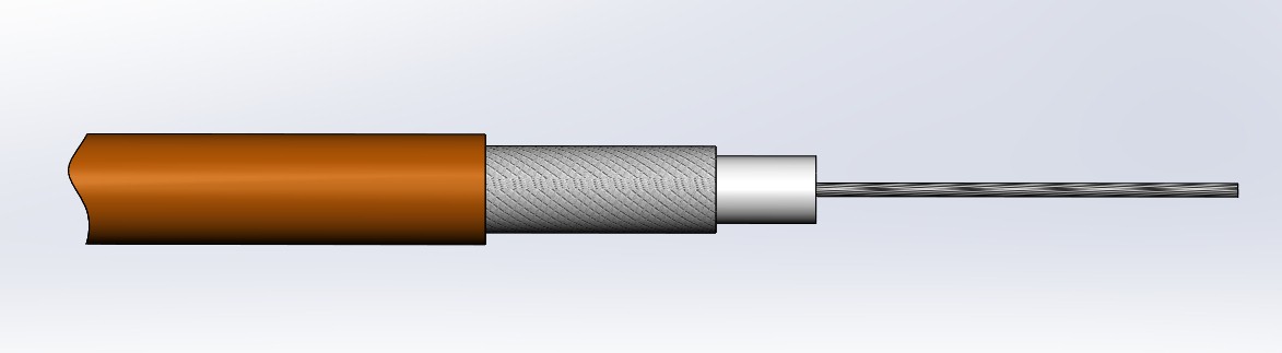
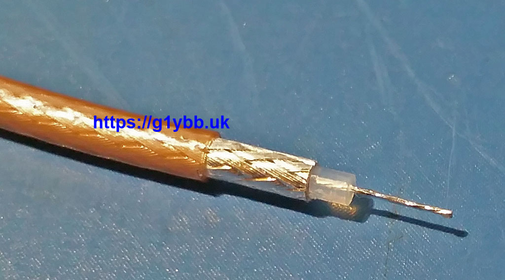
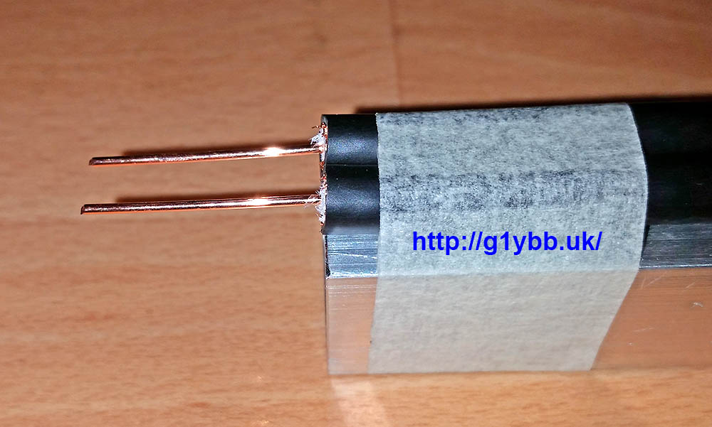
This DK7ZB match cutting jig will enable you to cut RG179 75ohm PTFE coax accurately and repeatably to the length required to make DK7ZB 28ohm matches. RG179 is chosen as it is easy to work with and is best used for antennas that will only be used as part of an array, or lower power use only. It should be good for about 300W PEP on 432MHz. This jig arrangement gives you enough braid to solder to with a very short length of exposed PTFE dielectric. At 432MHz you want to be keeping your ‘tails’ short and tidy for best results.
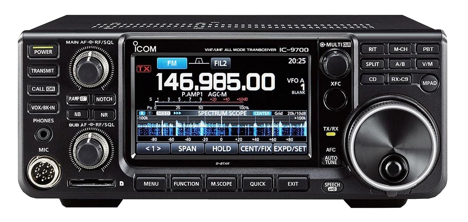
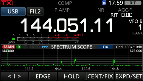
This is my brief Icom IC-9700 Contesting review based on my experiences in many RSGB and other contests, nearly all portable on a hill top and all three bands the IC-9700 covers.
I bought the Icom IC-9700 at the time the second batch of this radio to hit the UK were being hotly sought after. I had recently got the IC-7300 before it, which I also love, so I was pretty keen to get this one to add to my portable contesting stable. In it’s early days there was a LOT of negative talk about dynamic range and frequency drift, I’ll touch on that at the end.
I can honestly say right now, I love this radio! Review done.
Oh you want to know why? OK headline points for me…
Functionality.
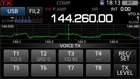
The IC-9700 has brilliant functionality for VHF contesting. The spectrum display is the biggest new thing to me (on 144MHz and up). Whilst this is brilliant for spotting signals on the band (and for this reason I think everyone ELSE should have one to find me!) not only that it has made the biggest gain to my 144MHz performance since getting the 9700. The way it actually did this, apart from the signal spotting ability, is to highlight why I was getting so much QRM on 144MHz. I always blamed other club members out portable nearby, line of sight, and some using FT-991 radios. Whilst they did batter me there were some nights I couldn’t find who it was killing me on the old school radio I was using. The 9700 soon showed me: I was getting awful QRM and the OVF warning in regular all night long pulses, as you can see all over the band, but particularly hammering me where I usually run (144.265). That’s no ham! We determined the source to be a local (100 metres away) pager system. For so long I had suffered this QRM without realising the true source. It took me a while but after buying one filter that wasn’t sharp enough I borrowed another bandpass filter that took out this pager QRM and left me with a bandscope a little healthier looking! Couple this with the excellent receiver the 9700 has and it has truly transformed my 144MHz operating, and also on the other bands based on the receiver.
In the first QRM image above you can see I have the inbuilt memory buttons showing. The IC-9700 has these for voice and CW (maybe data?) and these are a complete godsend. I use two for contesting and one for general calls pre-contest. They auto repeat and you can get an external box to replicate the first 4 buttons. (Another build in the future)
You can connect the 9700 to your PC with a simple USB cable and get CAT control and data in out for things like digital modes, computer reading and sending of CW etc. So much easier than buying a rig interface box. I just use CAT when I am contesting.
The 9700 will also record both sides of a QSO as you go onto the SD card. Useful for DXers and the RSGB recommend doing this for contests. I guess it would be good for resolving disputes.
Those are probably the biggest plus points for me that I use all the time. Receiver functionality like adjustable filters and notch filters etc are there but not unique to this radio of course.
Performance.
As I touched on above, the radio performs excellently in my opinion. It won’t match a top HF rig into a high spec transverter of course, and may not have the optional roofing filters some radios have, but I have done very well with mine and I have seen quite an improvement in my scores since getting this and the 7300 (which I also love and has basically the same features). I find the receiver excellent and pretty good at withstanding some strong QRM locally as we have a pretty good turnout in the UKACs at Hereford ARS.
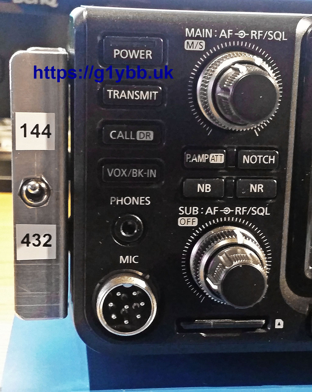
This radio does satellites (I know nothing about that) and can receive on two bands, but one of the first things I did when I got it out of the box was turn off the sub-receiver never to be used since. Until this March! March sees the RSGB March 144/432MHz where you need to operate on both bands at the same time. Not possible simultaneously as a single op but I set up with two antennas and two amps and ran on 144MHz and 432MHz, using CAT control from Minos to change bands by changing logs. Worked so well. However one thing I didn’t realise it could do was receive on one band while transmitting on the other. In the video below the 9700 is sat on top of the 70cms amp that you hear click when I Tx
I’m pretty impressed by that (as you can tell).
The “Bad Things”
When the IC-9700 was first announced there was a lot of talk about insufficient dynamic range to handle huge signals whilst receiving weak ones. Now whilst this might show up in a contest like 144MHz Trophy (IARU Region 1 in rest of EU) with huge signals from multiple antenna arrays and QRO amps (in fact our club station had such a complaint from a fairly close line of sight 9700 user) I can say that I have never had this that I can recall from another radio amateur. The only time my 9700 has shown OVF (overflow) is from the local pager mentioned above and from the Clee Hill radar station on 1296MHz. Bear in mind that I operate 11km away from G4ASR who has been known for being a very strong signal for many, many, many decades. (hehe Dave). I get strong signal QRM from him if too close in frequency when pointed at each other, but he has never put the 9700 into OVF (That is NOT a challenge Dave)
When the first units were received there was a lot of talk about temperature based frequency drift. It was the end of the world as we know it. Icom has since come up with a firmware upgrade to assist and GPS locked board and mods are available. I feel it’s worth mentioning I am using one of the very early units and it is as it came out of the box. No firmware updates have been applied. None have had anything I felt I needed. I don’t do data modes (to date) just primarily SSB. I have never had anything mentioned to me about drifting and never noticed anything on receive. That’s on all 3 bands. I do only normally use the radio on 10W on each band so I probably generate less of a temperature change. (They say it multiplies up on 1296MHz)
So if you want to actually talk to people yourself rather than letting a computer do it for you, the 9700 works. Works well.
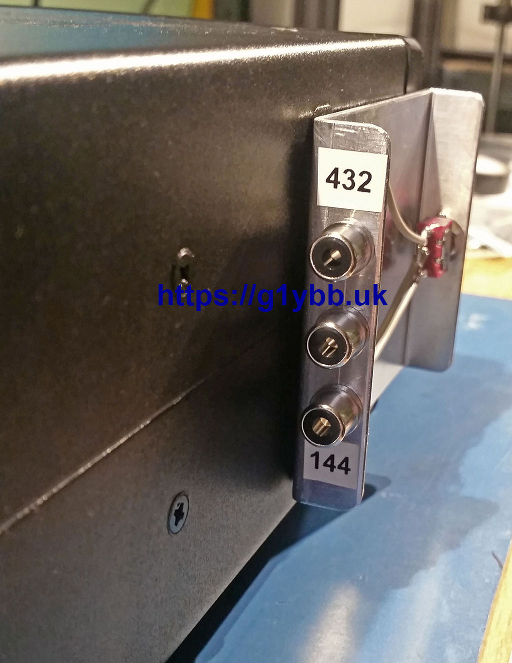
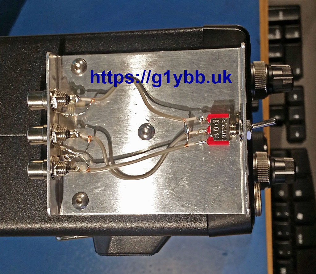
One real issue that has reared its head with me is the single PTT output for driving amps and transverters etc. There is only one contact available that grounds on Tx for all three bands. People have designed units that read the C-IV data and generate a band specific PTT output and I do plan to build one of these myself. For a recent dual band contest however I did something a little more old school: Summary.
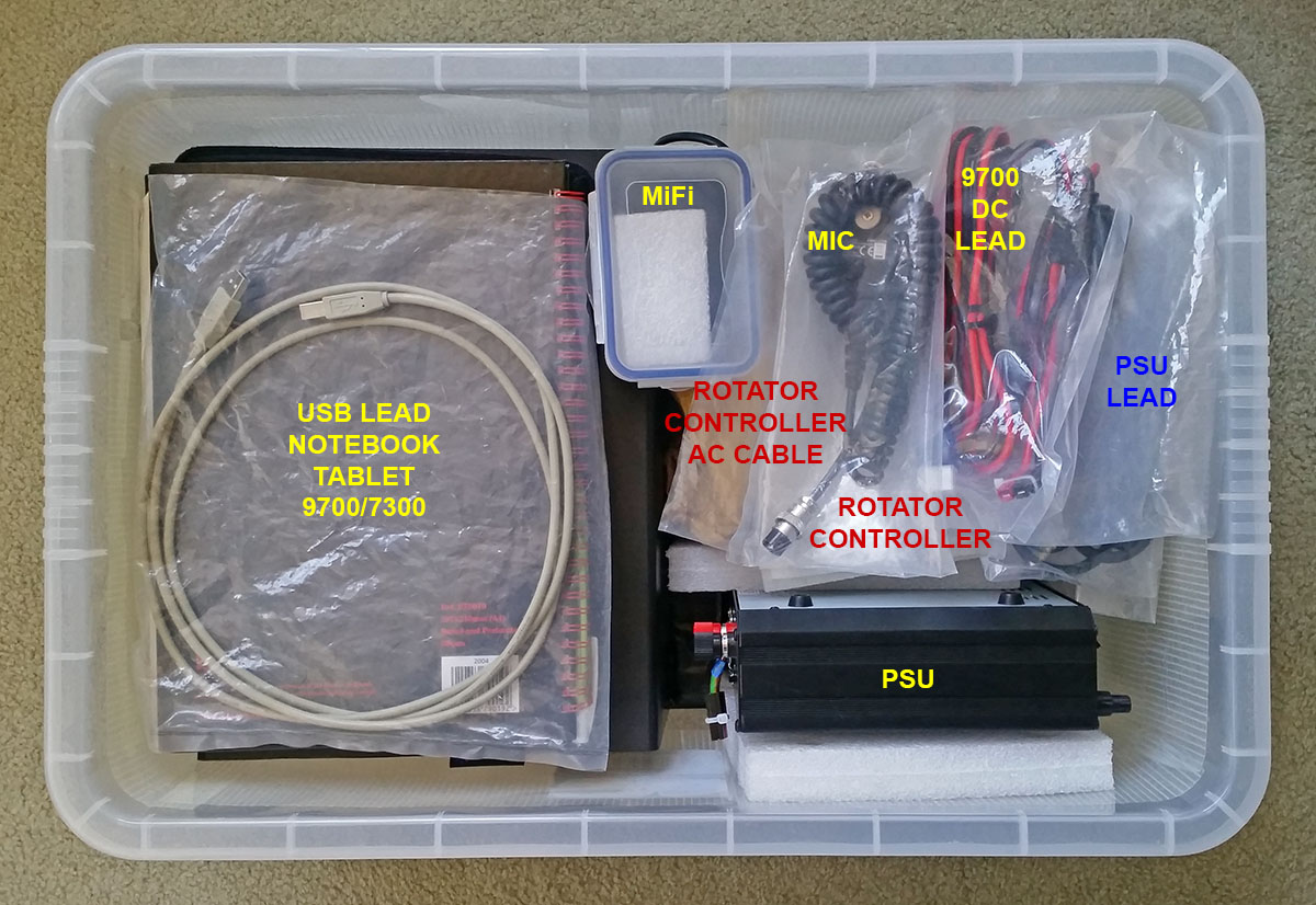
I am really happy with the purchase of the IC-9700 to accompany the also great IC-7300. One thing I like is the matching form factor. They are practically identical so I can alternate them in my portable box depending on the band I’m using.
My suggestion is to think carefully about what the naysayers are actually saying and decide if their nays will actually have anything to do with what you want to do with the radio. For example, I’m not currently interested in EME or data modes like FT8 so the drift ‘problem’ doesn’t bother me. If I decide to do data, then there are firmware and hardware solutions ready to solve that.
THIS IS NOT A FLIGHT/SHIPPING CASE!!
This is a FTDX-5000 transport case for things like taking it to field day etc.
As the FTDX-5000 is an expensive and heavy beast I designed and made a transportation/storage case to fit it. I’d looked at what you could buy and everything was huge and heavy, increasing the size of the 5000 by a considerable amount. Something simple, low profile and low weight was required.
Images are clickable for larger version.
Below is the resulting case. It’s powder coated aluminium, adorned with protective foam so the radio never gets scratched or dusty/wet (just care fitting the lid is all required) and has latches to quickly but securely lock the lid on. Once in the case it can be carried around without fear of accidental bumps, things falling on it, kids fiddling or rain (to and from car etc).
The box is designed to enable the radio to be operated whilst still in the base, and even offers a handy place to hang the standard microphone: continue reading
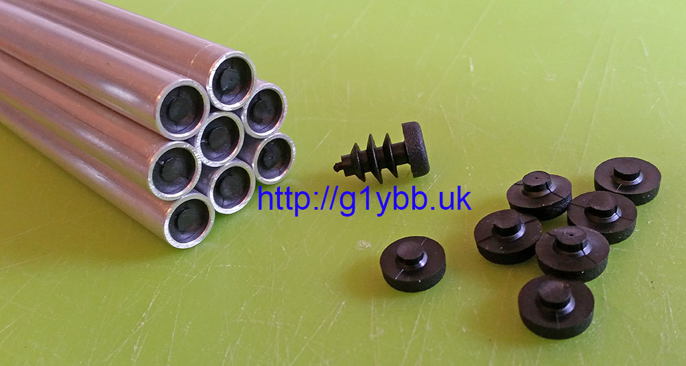
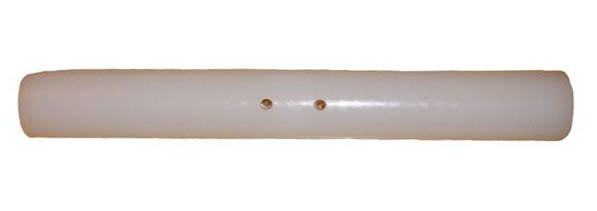
When making my yagis I prefer plugging yagi dipole ends so water cannot run down the tube and enter the dipole housing with its corrosive end results. Also, it does stop spiders moving in and making a right mess everywhere.
Many people do not like to add caps to the elements for concerns over altering resonance, so I just cut the cap off and push them in so they are fully inside but water cannot enter. Simples.
These plugs were from nuxcom.de but he has ceased trading now but they are available at various places including Tino’ Funkshop but these days if you are in the UK it’s best to look more local.
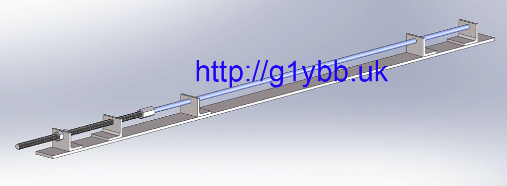
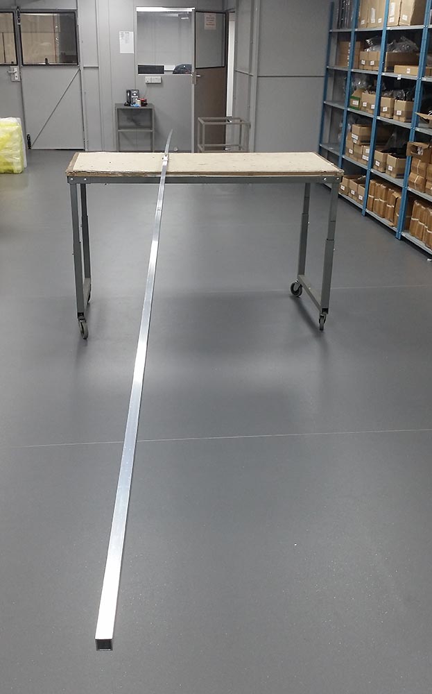
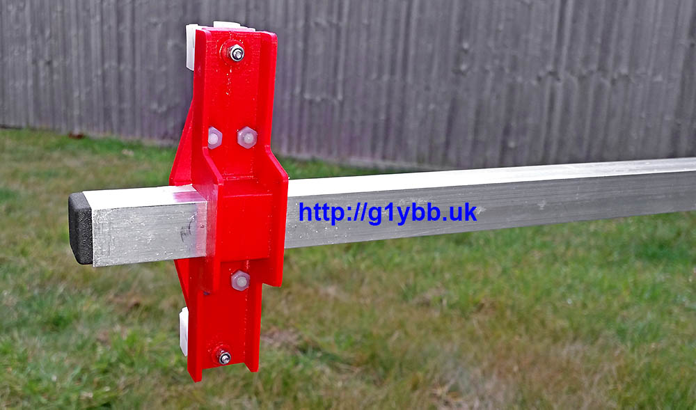
I planned to build more 144MHz & 432MHz DK7ZB yagis for contesting to use in arrays so I wanted to ensure I could make them accurately and repeatedly and also without taking forever doing it! Thus I needed to come up with an efficient cutting jig to make accurately cutting yagi elements to size fast and reliable.
I would use some threaded bar to adjust and set the length and steel angle for the supporting the aluminium tube and cutting the length. First I calculated the range of length between the longest reflector and the shortest director then a quick knock up in Solidworks gave me the length of stud required and ideal places to weld the angle to do the cutting. The studding is M12 because a nut for M12 will take a 10mm ali tube with a little clearance. The long M12 barrel nut (Screwfix, few pence) is locktighted in place. From the left the angle brackets have the following holes: 12.5, M12 tapped, 10.5, 10.5, 10.5:
Some cutting, drilling and tapping later and I have this (the observant will note it’s not exactly the same as the intended design-more on that accidental stroke of luck later!): continue reading
Now it’s towards the end of June and I have been listening to the other club members I chat and contest with reporting on all the times 50MHz has been wide open on sporadic E, I decided today I would knock up a simple antenna for 50MHz for the garden. My location is not suitable for any real antennas due to neighbour issues so I thought I would make a wire delta beam and mount it fairly low as I have a suitable 2m length of plastic pipe I could use for the cross boom. A quick look at the design scuppered those plans as I had no suitable 75ohm coax here.
I then considered a simple aluminium dipole as I have loads of 1.5m lengths of 12mm tube in the garage. Then it came to me in a eureka moment. A good old trusty inverted vee would be easy to make and do the job nicely!
Since I made my first 20m inverted vee dipole I have since butchered it by cutting off the coax to use elsewhere and it has been lying around the garden for a year or so in the grass in the corner of the garden. Rescue that and put new coax on and I am good to go!
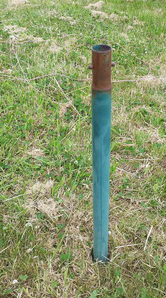
Next (as seen already above) I needed a pole. I took the bottom 3 sections from my 8m SOTA fishing pole which gives me about 3m of lightweight but stiff pole. In the garden there was fitted a rotary washing line with a two part stem set in the ground. Amazingly it was the perfect fit for the bottom section of the pole! The two sprung plungers even stopping it flapping around:
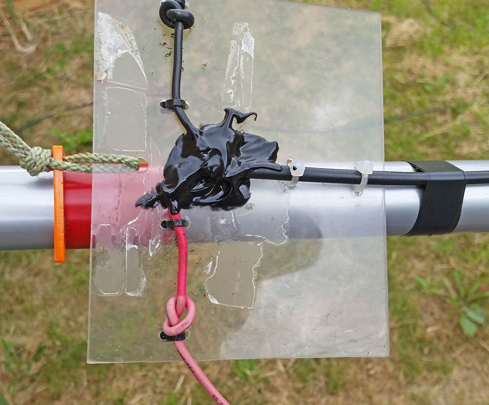
Into the HF antennas odds and sods box and I got out one of the SOTAbeams lasered guy rings I bought to hang the dipole from. I slid it down to a reasonably but not excessively snug point and wrapped some tape around below that to stop drifting lower and possibly cracking as the plastic is fairly brittle feeling. I also sealed the feed point with liquid insulation tape which is great stuff and taped the coax down the pole to take the weight of the coax, which is longer than I need and only RG223 but I am just looking for something to get on the air and do some tests:
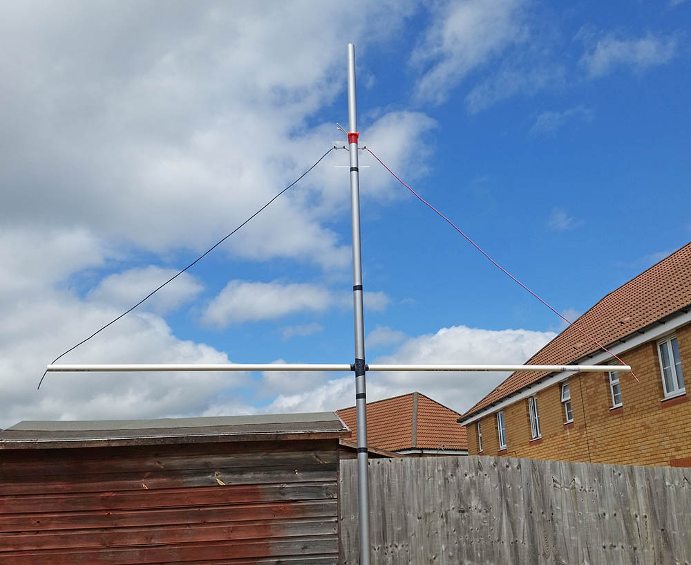
With my HF dipoles I usually peg the other end to the ground with a length of string to insulate and keep the voltage maximum point off the ground but that really didn’t seem a plan. So that delta beam boom was called into play as a dipole spreader:
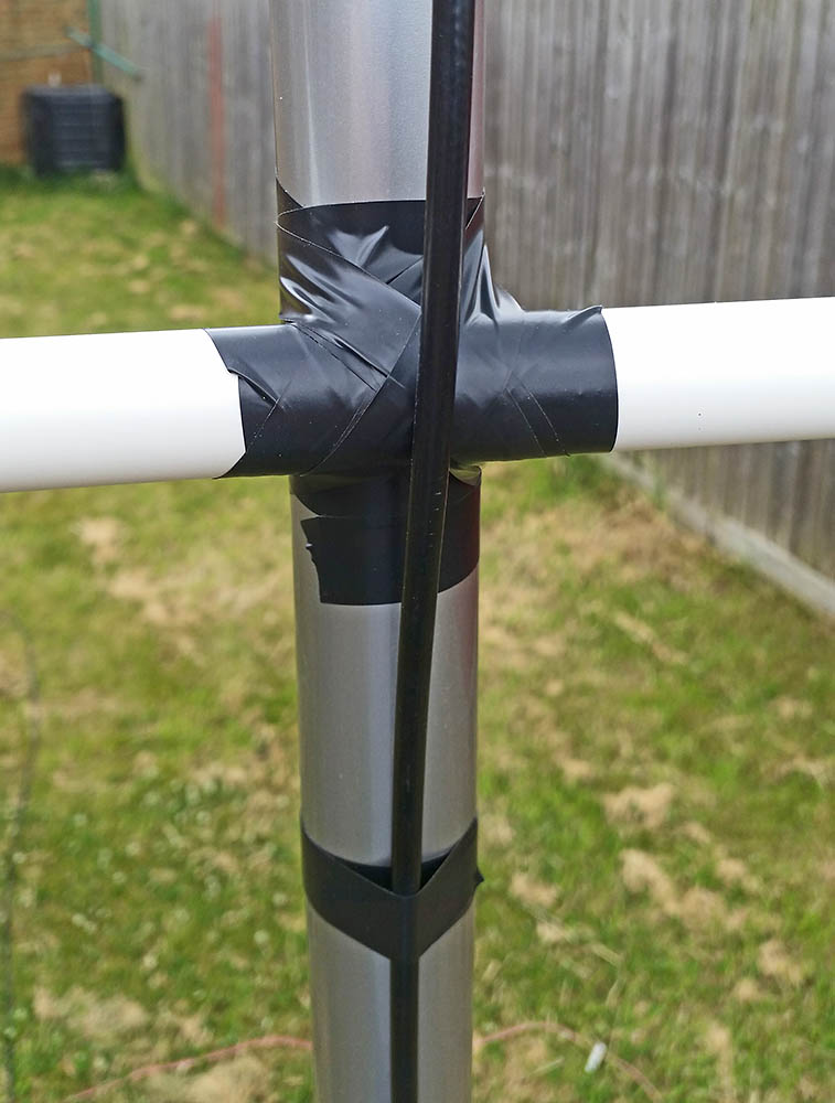
It’s literally just lashed on with insulation tape:
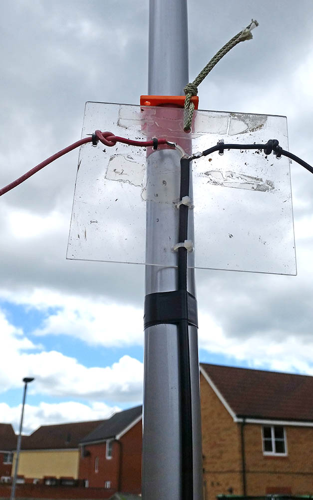
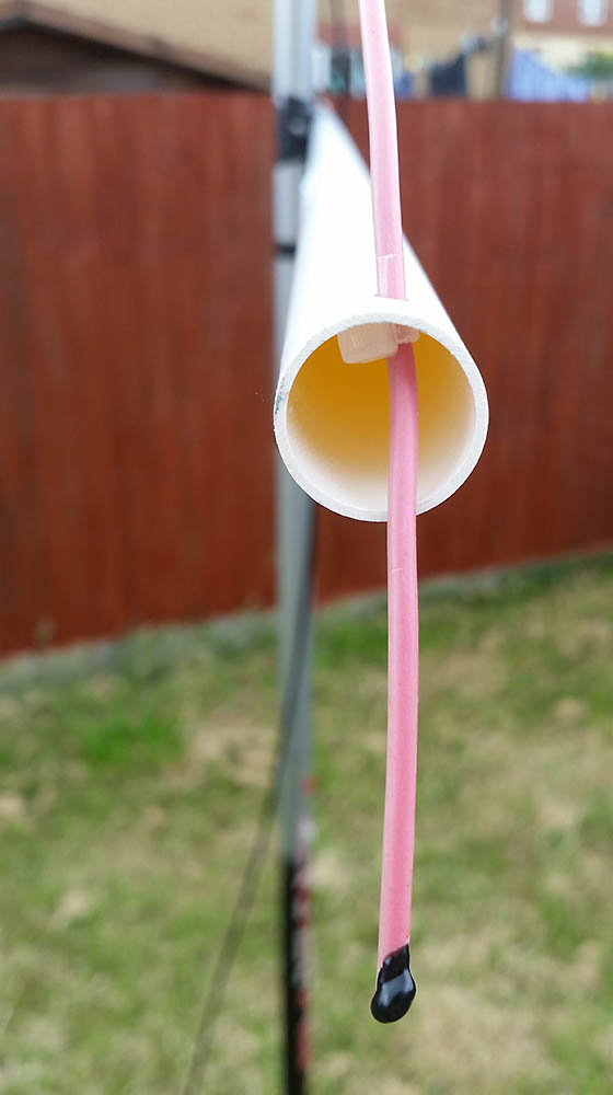
At each end I drilled a single hole to thread the wire through which actually retained the wire quite well due to the tension and angle. But I backed that up with the ubiquitous cable tie. Also visible is a blob of the liquid insulation tape on the end of the wire to stop water seeping up the wire via capillary action:
Here is the finished set up ready for tuning. On the left of the image you can see the coax running into my custom wall mount coax connector box:
Talking of tuning…
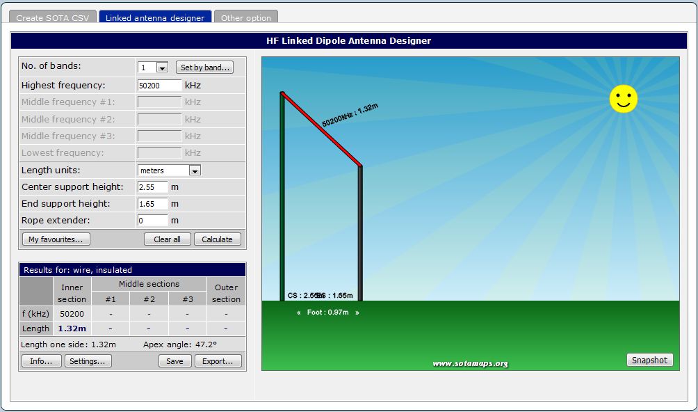
To ‘design’ the dipole I use done of my favourite sites I use for all my HF dipoles over at sotamaps.org. (Click on the 2nd tab for the calculator). I put in the centre height measurement from my set up and adjusted the end support height to get a little under a metre horizontal distance between mast and end support. You can set the wire type via the settings button. You can see it offers me 1.32m for each side. So I cut mine to 1.42m to start as it’s always easier to trim than add!!
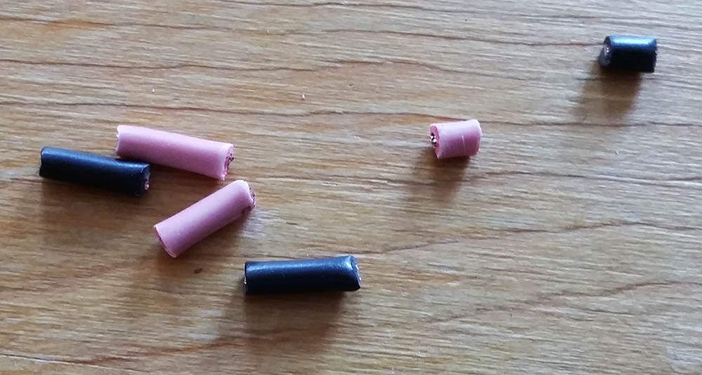
First measurement showed beautiful resonance a little under 50MHz, so I trimmed 10mm off each end. Nearly at 50MHz, so 10mm more. Resonant now more in the CW end so I took off another 5mm. The final cut length is actually 75mm longer than the designer suggested, so it could be my selection of wire should have been for a thinner one or thicker insulation than I chose. (that’s ex red wire with a dose of UV fading applied!):
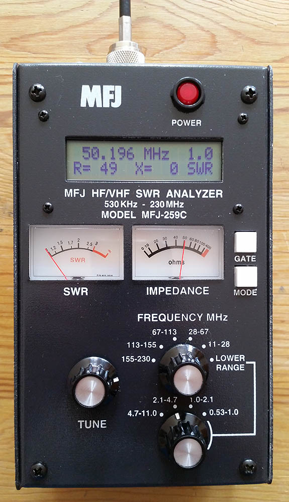
SWR 1:1, zero reactive component and 49ohms resistive component (50 ohms a tad higher up the band but still in SSB section). I’ll take that!
Plugged into the trusty Yaesu FT-857D and a quick scan showed some Es stations calling. Found an EA station and called him, replied to me first time! As did the next 4 stations. Nice one!
So there you go. It is dead easy to get on 6m even with very awkward neighbours and small gardens. 50MHz truly is the magic band when those Es open up too!
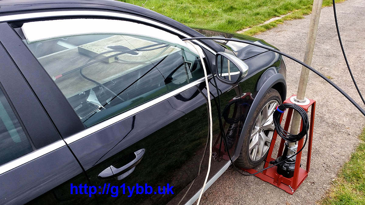
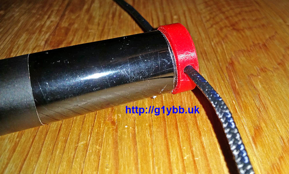
Nearly all of my radio is done portable in one way or another. When I am car portable like many people I bring the cables in through one of the car windows. As I like to operate both through the winter and in the summer I wanted to keep the cold and rain out in winter and the flies out in the summer.
My simple solution to this is a strip of 1 inch thick closed cell foam with a shallow slit in one edge to fit on the top of the window, and a notch for the cables. Simple but works for me. It also doubles as rattle reducing packing on the way up and back!
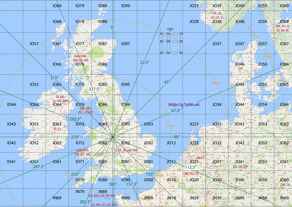
With the introduction of the B2 scoring system in 2017 I decided it was time to update my VHF contesting map that I use to help me aim the beam and find multipliers and bonus squares when out portable.
I have beam heading marked centred on my portable locations. They are close enough together at this scale to us just one point.
I usually take an A4 print of this map with me to refer to but the PDF file is fairly high resolution and should be printable at least A3 size at decent quality. Here is a 100% view of the map to see the detail:
You can download it if you wish but if you wanted one centred on your location you can always email me (my email is on the home page here). The annotations are all done in vector layers and can easily moved around to suit. Here is my PDF for a look but it’s probably only any use to David G4ASR and other portable stations in my area.
Edit:
Several people have asked for a copy of the map centred on their locator so one of these below may be of use for you. The centre point of the beam headings covers a couple of squares around the actual centre so one near yours. If not you can always email me.
NEW MAPS APPEAR AT THE TOP. Below those is a sorted list of previous maps, and below those are 2017 B2 (boooo hissss) maps.
Towards the end of 2016 the rules and days for the UKAC series of RSGB contests were changed. The 50MHz and 70MHz UKAC events were moved to the 2nd and 3rd Thursday of the month respectively. This opened up more opportunities for me as working a Tuesday night contest means rescheduling my Tuesday to a Wednesday and means my Wednesday is busy as heck and it’s at least Thursday before I can even look at the tablet to get the log updated. But a Thursday I am usually free so I can get on another band. As I have no 70MHz Tx capabilities I decided 50MHz was the way forward for me. I have an old home made 5 element yagi we used to use but I wanted a newer better performing yagi. I am getting awesome results with my 144MHz 9 element yagi I decided another DK7ZB sounded ideal.
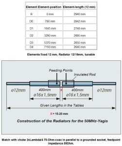
I chose the 6 element 7.2m boom version as I plan to only use it car portable and it’s only 1m each end longer than the 144MHz yagi I’m using. Also it has a great SWR curve. All dimensions are available on Martin DK7ZB’s site:
This design only had figures for 12mm elements. That was OK as I can get 12mm pipe clips like I used in the 144MHz yagi. But it turns out buying 12.0mm tube in lengths greater than 2000mm in the UK is exceedingly difficult. It had been suggested to me to use 12.7mm tube as that would be easy to buy in the UK but would require recalculating the element lengths. Not only that it would prevent me from being able to use the fast fit pipe clip I wanted to use. After much searching and asking in various places I had to admit defeat and arrange with Attila at nuxcom.de to ship (at some considerable expense) some 3000mm lengths of 12mm tube, along with several other antenna parts and also some 3000mm lengths of 10mm element tube.
For this yagi, unlike the 9 element for 144MHz, I had no plans to take it backpacking portable so I decided it only needed a 2 part boom. I was easily able to get 5000mm lengths of 20mm boom for this. 20mm is quite small sized boom for a yagi of this size but my element mounting plates are designed for 20mm boom only. I’ll be using truss supports and side supports if required to stop it flexing too much. The 5.1m long 2m yagi was nice and sturdy with its trusses in high winds on the top of the Black Mountains. Although it’s only 1 metre longer each end, it makes for a big boom!
Once the element positions were marked up the 5 parasitic element clips were fitted in the same manner as the 144MHz 9 element. On this yagi the driven is too big for the element clips so that will need a more conventional box:
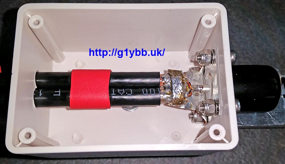
For the feed box I decided to go for a beefed up version of that I did with the 144MHz 9 element. I chose an ABS box from Farnell as it is quite thick walled and with a decent lid should be pretty stiff and is also IP65 rated (before I start drilling it). In order to get a suitable height so the driven element 16mm sections could be on the same plane as the parasitic elements it came in quite large at 200 x 150 x 55mm but that is OK as the driven on this 50MHz is quite big:
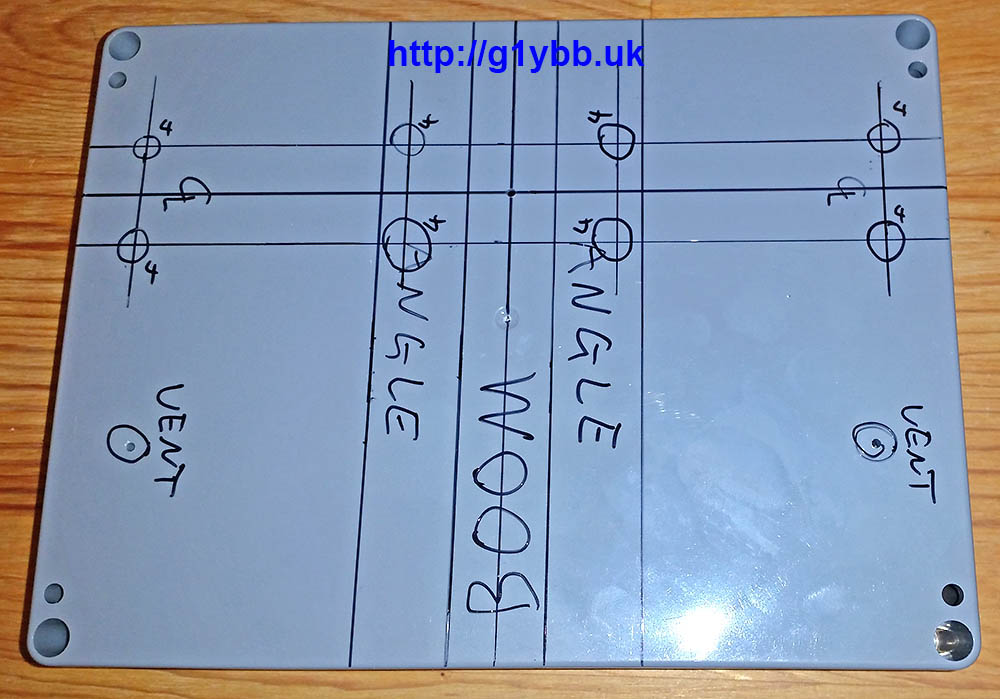
Here it is marked up for drilling. Marking needs to be spot on as this is what makes the driven element parallel with the parasitic elements in both planes so is crucial!
This is the centre point of the dipole box used for locating it on the boom in exact position:
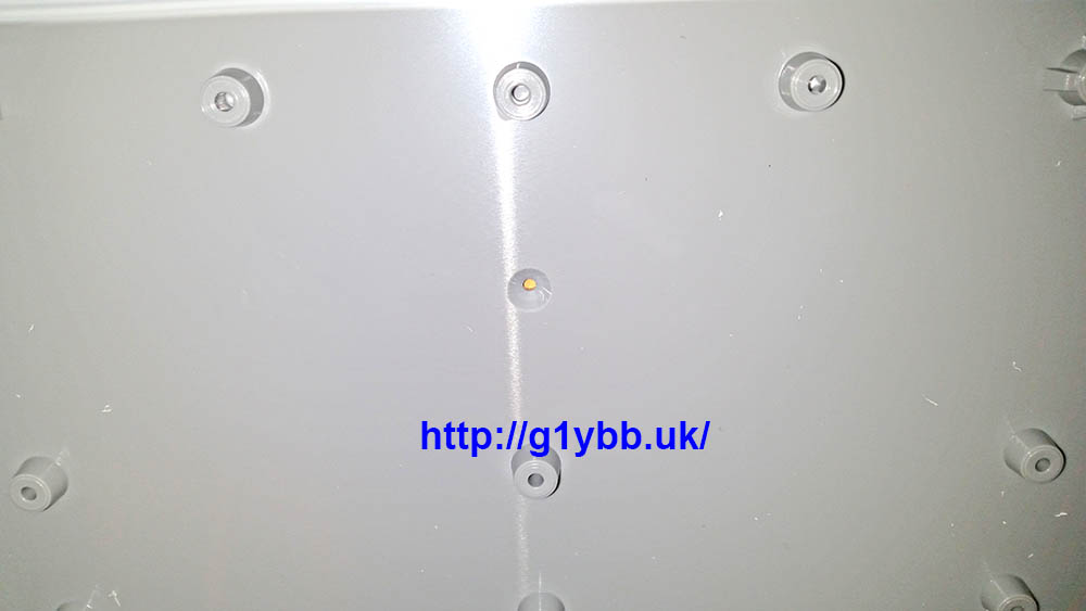
To enable stability and strength for the 3 metre driven element I am using some 19mm angle. The sighting hole above lines up with the centre of the scribed line:
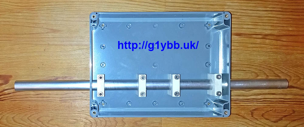
To mount the two halves of the dipole I got my good friend Paul to 3D print some two part clamps in ABS to my design so the centreline height of the driven element above the boom matches the parasitic elements so all elements are in the same plane. Here are the clamps after drilling and fitting to the box with some 16mm tube to check alignment:
To fit the dipole box I drilled and tapped an M2 hole in the centre point of the boom on the scribed line as seen above and screwed the dipole box in place using the 2mm sighting hole. I then fitted the reflector and first director and ensured they were all parallel and drilled the box to fit the two angle pieces:
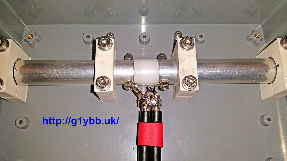
When I bought the element materials from nuxcom.de I also bought their dipole centre for 16mm tubing:
Which is very chunky and strong. But the 16mm tubes fit inside the joiner and I couldn’t see how one would get a good secure contact to the elements. So I got another good friend Ed to turn up a piece that would fit inside the elements like the nuxcom one for 10mm elements does. Here is the mechanically finished dipole centre:
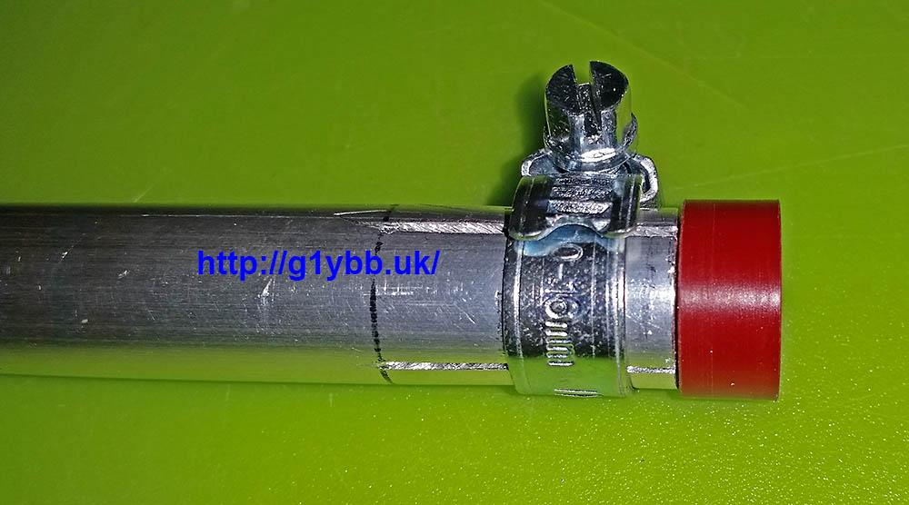
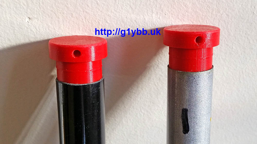
The eagle eyed may be wondering what the red things are in each end. Well as I am using jubilee clips to clamp the 16mm tubes down onto the 12mm main driven element parts, once they are removed for transport (this yagi is for portable use remember) the jubilee clips are free to fall off unless clamped down. So my I got some plugs 3D printed to clamp onto to retain the jubilee clips and also prevent any dirt ingress during transport and storage:
Now the dipole needs the DK7ZB match. I’m using the same WF100 75ohm coax I used on my 144MHz DK7ZB, which is fairly low loss for its size, and is not too big or heavy. Its claimed velocity factor is 0.85 so I worked out the length as so:
300/50.150 = 5.982m full wavelength
5982/4 = 1495.5mm for quarter wave
1495.5 x 0.85 = 1271mm
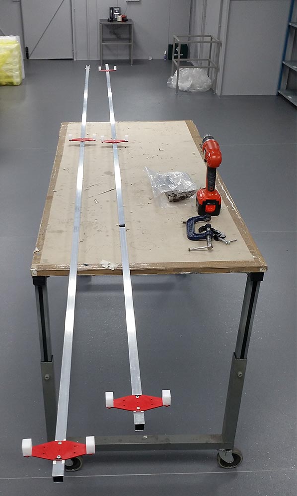
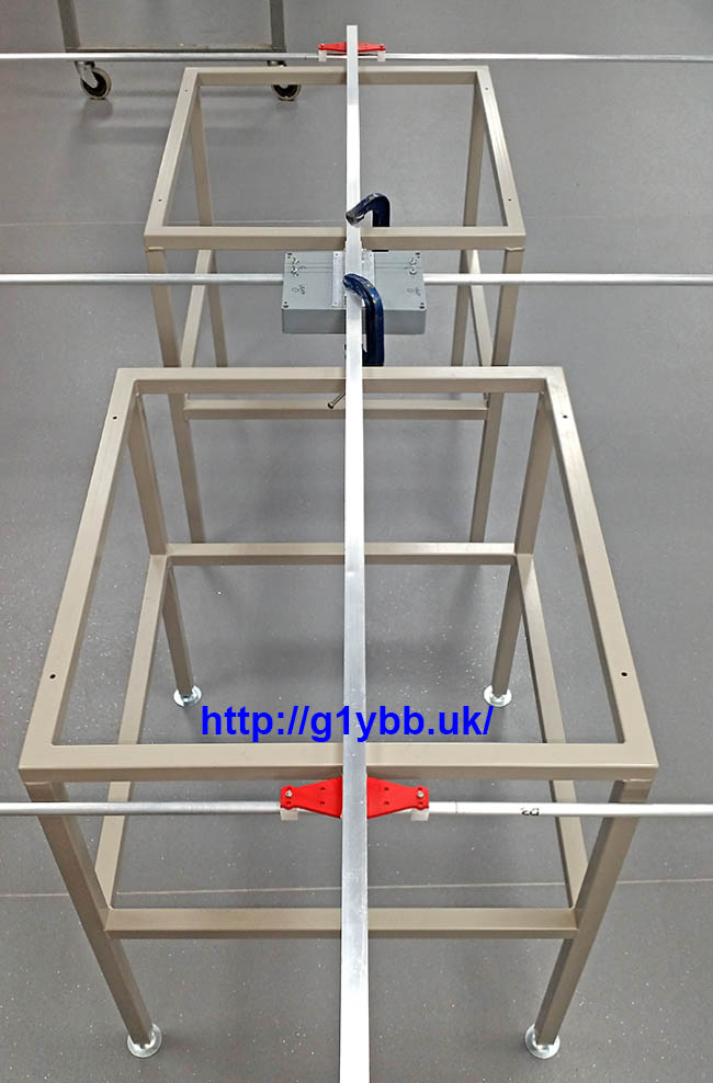
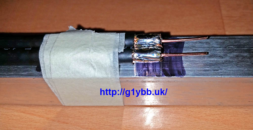
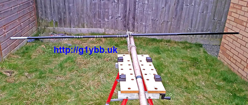
As before I used a section of boom to tame the curling of the coax to allow accurate measurement and cutting of the lengths:
One end of the match fitted:
A picture of the process in operation in the ‘workshop’:
Other end of the DK7ZB match completed:
Apart from the bracing the antenna is pretty much complete except for the fact that the element mounting plates are not really man enough for 3 metre long 12mm elements. They were designed for the 144MHz yagi and only 1m long 10mm elements, which they are perfect for. With the larger elements this is how they were flexing with gentle persuasion:
A quick chat with Paul and he drew up a two part brace that he could 3D print me and soon they were in the post!They utilise the same holes already in the element plates and wrap underneath adding strength without interfering with the element clips at all. I used M4 nylon screws to add extra fixings without adding extra metal, the only metal nut and bolts holding the element clips on:
After fitting the new bracing parts this is the flex with quite boisterous provocation:
Much better!
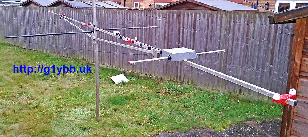
My next consideration is bracing. Long supports were made and fitted utilising the same fittings as on the 144MHz yagi. In fact as I write this I have started work on a 70MHz yagi. All three will fit on the same fittings on the portable mast, and the 70MHz yagi will re-use one of the 144MHz yagi braces and one of the braces for this yagi. The angle of the supports is quite narrow but they do support the boom and keep it straight. This yagi also will need side guys to protect it from the wind. I have several bottom sections of 4m fishing poles left over from HF antenna projects so I utilised two of those. Again Paul quickly produced some parts for me. Some ‘plugs’ to fit to the mast plate to mount the poles onto:
And some stoppers to go in the end of the poles for the 3mm dacron cord, which is very strong and has very little stretch. The stoppers are a good interference fit:
Side guy poles fitted to the mast. These are a friction fit to the ‘stoppers’ and quickly assembled on site:
The sides guys clip onto a plastic bushed (thanks Paul!) bolt on the boom supports with a single karabiner each end. Very quick to deploy:
Next step was to test it! This was done after work on the Wednesday before the first 50MHz UKAC in Jan 2017 the following day! It was reading 1:15 throughout the SSB portion of the band, which was slightly disappointing. There was no time to look into this as I needed to get back home (testing was done in a mountain’s car park) and pack for the next night’s contest!
On the night of the contest the in radio SWR reading was quite low so I was happy the radio was feeling OK about the match and used the new antenna for the first 50MHz contest I have done in 20 years. The yagi seemed to work pretty good and I even managed to beat G4CLA in the AR section of the RSGB 50MHz UKAC January 2017, which I was delighted with!
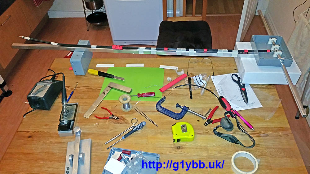
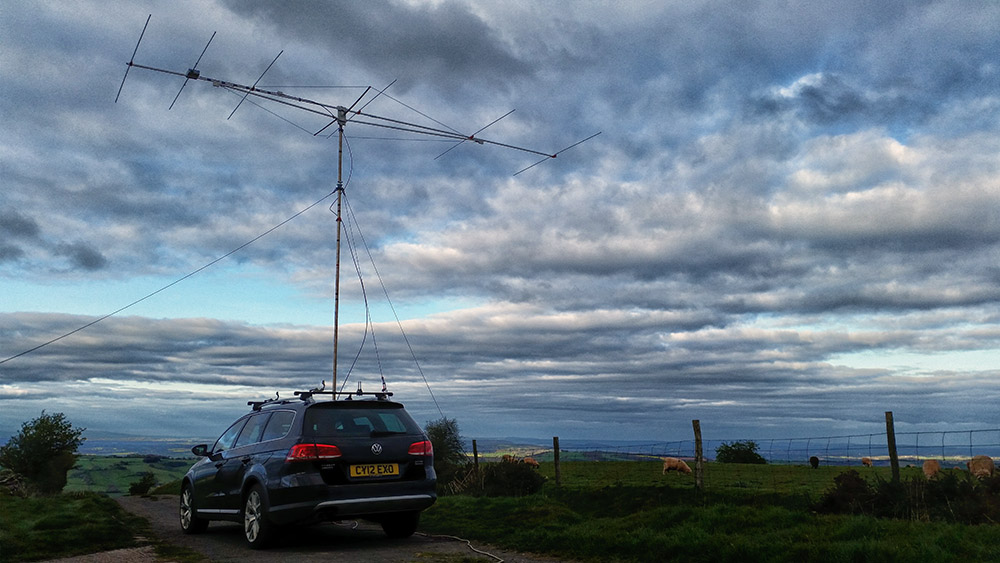
Here is the beam on my portable setup. Longer than the mast is…
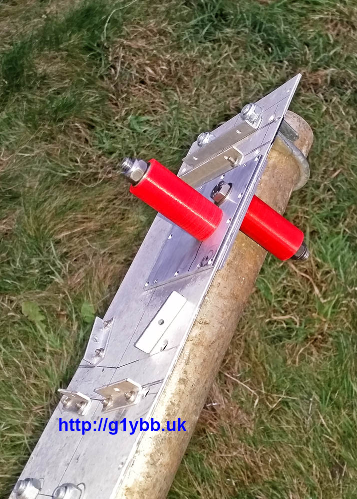
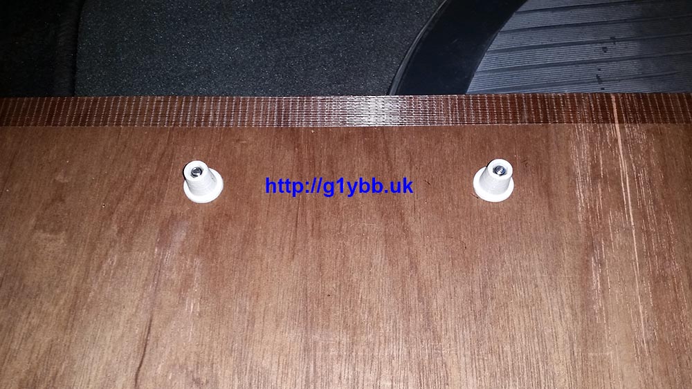
After I made a post on the UK VHF Contest group on Facebook I got a reply from Dave G3WCB showing his cool car portable setup. I had already very recently thought of doing something similar but seeing his setup gave me an idea for a simple and quick update to my plank of wood.
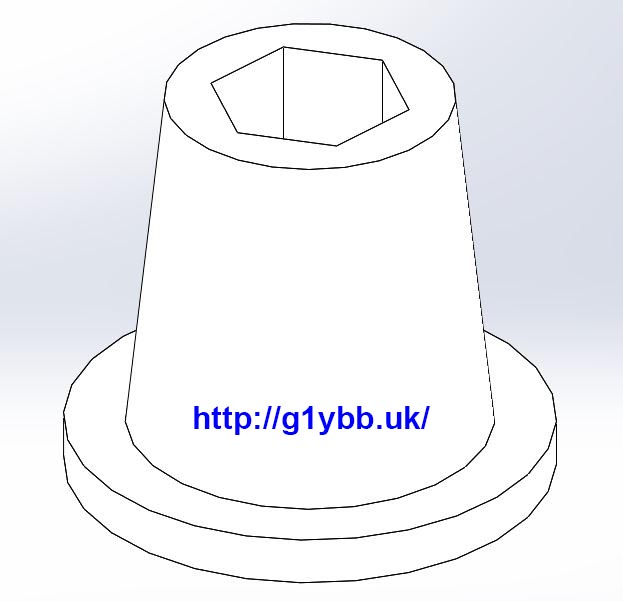
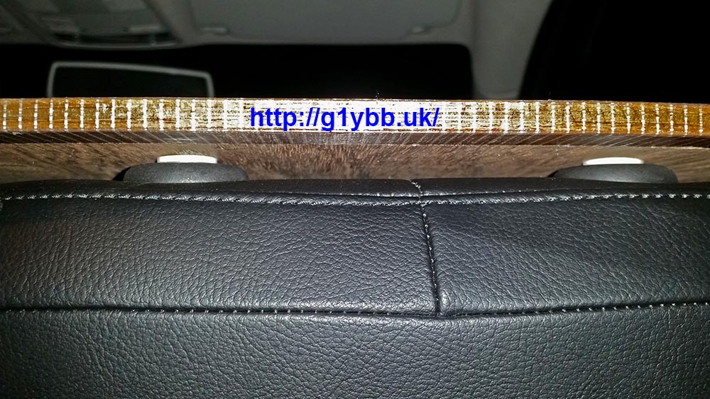
I already locate it over the steering wheel for some security to stop it toppling over and trashing my radio gear but seeing Dave’s set up I realised I could secure the other end with two simple locating pegs and make it virtually idiot proof. Out with the 3D design and quickly knocked up a tapered peg to fit the headrest sockets. I included a recessed hex to take an M4 nyloc to save having to over tighten a bolt onto wood and split it:
Shortly sent the file to my very generous friend Santa Paul who 3D printed me some and they were in the post!
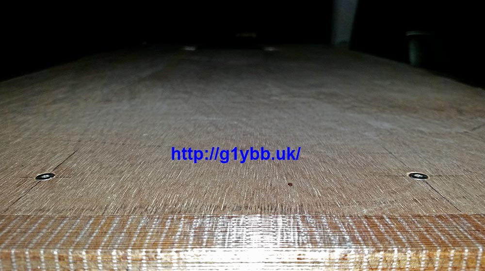
A quick measure in the car and drilling and job done:
Fitted to top of driver’s seat:
Just needs a radio and rotator controller: