Having recently built one of the new (to me) DK7ZB designed yagis for 144MHz I am finding it’s performance to be amazing. It even feels like it performs better than our old array of 2x 19 element MET antennas. So I wondered how they measured up for gain.
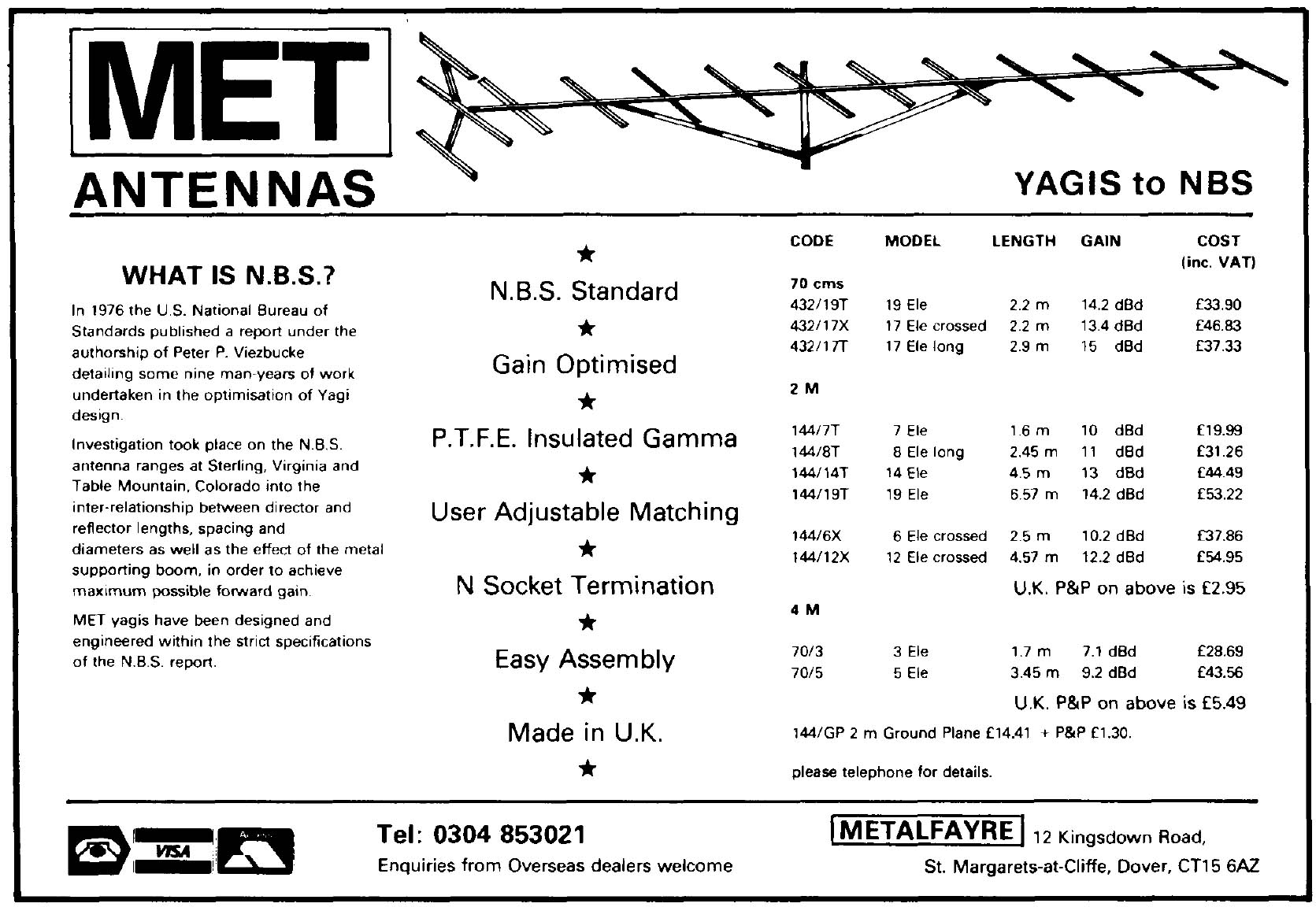
The 19 element MET antennas we used back in the 1980s and 1990s and Google was struggling to come up with the good for me to see what they were specified as to compare. I eventually found this advert in a PDF for a construction article from a 1983 Practical Wireless magazine so I thought I would share it for anyone else who might follow the same path.
So our 19 element MET yagi was 14.2dBd from a 6.57m boom.
My new 9 element DK7ZB is 12.5dBd from a 5m boom.
To get 14.2dBd in a DK7ZB requires a 8m boom. Hmmm.
I’m not sure I fully trust the claimed gain on this advert! 14.2dBi maybe, but I am not convinced on 14.2dBd. The ‘feel’ on the air of the new single 9 element DK7ZB is just great comparing to what we used to work on the 2x METs. I am getting great signals from familiar places and people. I am using a new-ish radio (FT-817) though that is not what I would call a top spec VHF contest radio. I am using a lower mast and probably better quality and shorter feeder I guess. I must dig out the Yaesu FT-225RD I used to use and see how it ‘feels’ on that. One thing I have thought of is I know we mounted one MET at top with support below, and one at bottom with support up. I can’t remember if we arranged the feeds to be on same side! So we may not have been operating as efficiently as possible.
All in I am loving the DK7ZB and can see why lots of the contest groups have them.
As I have always operated way more as a portable station than a base station I have operated from the car many times and in many ways. Some not as comfortable as others that’s for sure. It gets tiring twisting to one side or hunching over. In the end I came up with a simple solution for me that enables me to easily set up and have space, and be comfortable operating, which is important if you are spending a long time operating like in a contest.
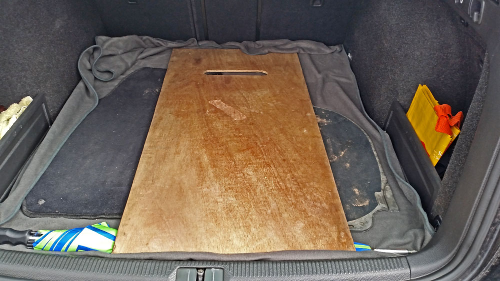
Basically, a plank of wood!
More accurately it is a small sheet of plywood sized and modified for purpose to make a flat table in the car to carry the radio and any ancillary units like batteries, PSUs or amplifiers etc. It’s strong enough to support a 4CX350 based 200W VHF amplifier.
The sheet is sized wide enough to fit in most normal cars and long enough to reach from the top of the dashboard to just past the back of the driver’s seat. There is a slot cut to allow it to slip over the steering wheel:
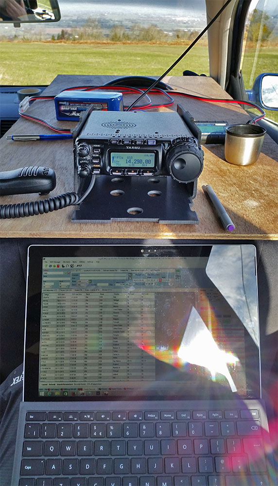
I keep it in the boot ready to go as it doesn’t really take any space. I just take the head rest out of the driver’s seat and sit the board on the top of the seat. The slot for the steering wheel allows the board to sit on top of the dash and adds a level of security from catching a sleeve on a corner and knocking it off. In my shiny new car I just add a towel over the steering wheel and dash and another on top of the seat to protect them from any markings. The two head rest entry points and top of the curved dash make a tripod style stable platform. And the weight of the radio and batteries keep everything steady.
I use my backpacking batteries because I don’t have a DC feed at 20A to the car battery for the radio and I don’t have to worry about draining the car battery if a pileup comes my way.
I pull the steering wheel all the way forward to drive anyway, but this means the wood extends back enough to sit normally in the back seat without even moving driver’s seat and I can sit with my back against the back seat (rather than hunched forward) comfortably and operate. In fact these days as you see, I have the tablet on my lap. The most comfortable car portable operating I have found, and I have done a lot over the years!
This is about the 4th or 5th car this board has seen action in and it is now into it’s 4th decade (with about a 2 decade break).
I was scrolling down my Facebook feed and spotted a post in I think one of the SOTA Facebook groups mentioning a BX-184 CQ Parrot. It looked interesting at first, then awesome! Within 20 minutes I had it ordered.
This is a modification to the standard MH-31 microphone that comes with the FT-817, FT-857D and FT-879D etc. It will record and playback a message, perfect for calling CQ Contest or CQ SOTA etc, but without the requirement to carry and connect up another gadget as it fits completely inside the microphone body. It was designed by Oliver DH8BQA and he describes it on his website here http://www.dh8bqa.de/bx-184/.
It is available for sale on the German Funk Amateur site here Funk Amateur BX-184. However they also do another kit that includes an MH-31 microphone body if you don’t want to disturb your original mic and that is the option that I took Funk Amateur BX-184M. The website is all in German so if like me you don’t speak German Google Translate will help a lot! There is also now a USA vendor here http://www.box73.com/product/2
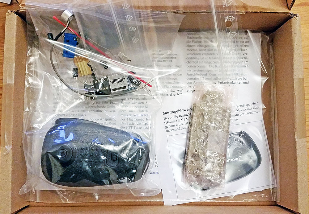
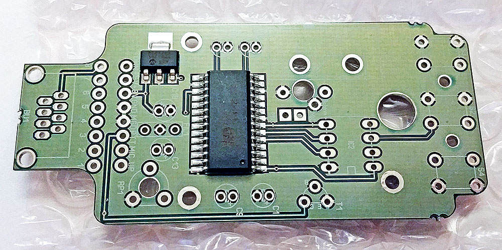
It came pretty quickly and this is what you get in the box:
A complete kit with all you need. The PCB is part SMT (surface mount technology) and part through hole components. You just need to fit the through hole components.
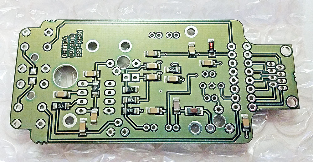
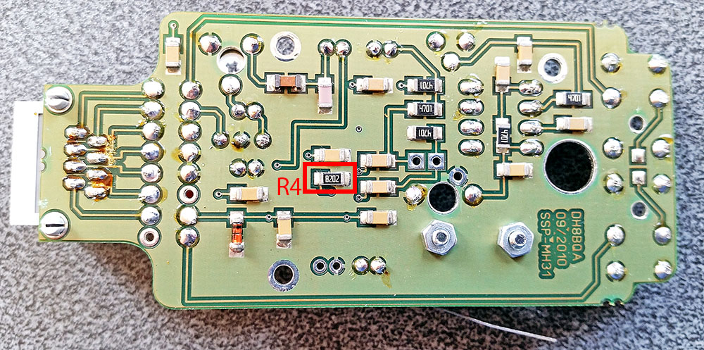
The double sided PTH PCB is very nicely built.
Top:
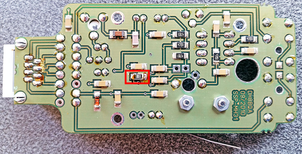
Bottom:
Before it arrived I did some research and found some mods made by DG2IAQ on eHam which sounded worthwhile:
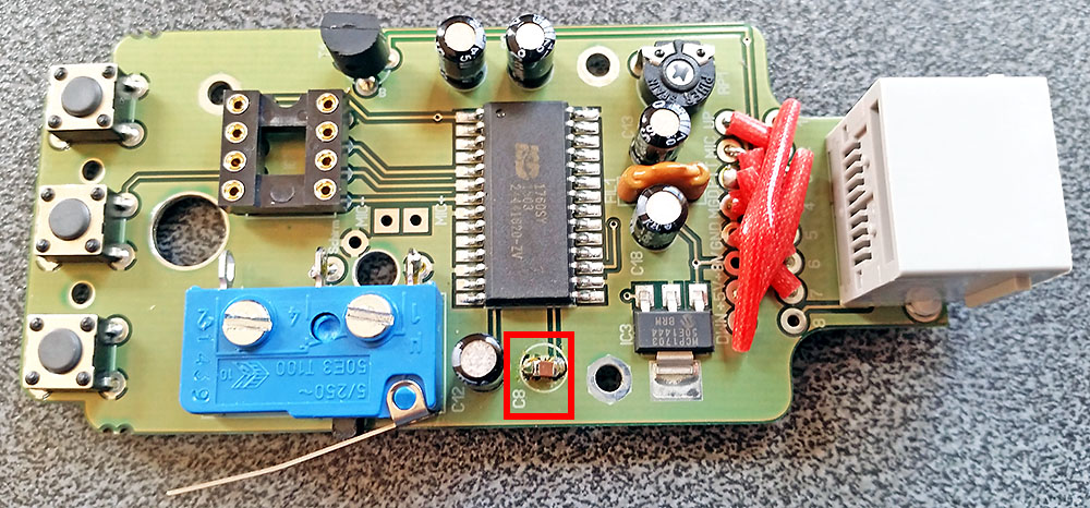
Mod 1:
“I do always replace C8 (4,7µF) by a nonpolarised SMD 1,0µF to fasten up the AGC. With this Change the internal AGC works more as a mic compressor than as a (slightly delayed) mic Level limiter.”
Mod 2:
“And for the first time I changed R4 (82k) into 56k to bring the sample rate from 8kHz up to 12kHz (by a shortened play time of 40s instead of 60s, but that’s still more than enough for my needs). This change gives even more punch for the replayed calls as the sound is a little more high-pitched afterwards. You simply can solder a 100k SMD in parallel to R4 instead of completely replacing it.”
I emailed Oliver DH8BQA for his thoughts on these mods and he confirmed they should be worthwhile.
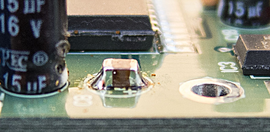
So I decided an 0805 ceramic chip 1µF capacitor would fit best across the pads for the 4.7µF electrolytic it was replacing:
I should have fitted this first as the 15µF cap next to it made it awkward to get a good solder joint on the GND side of the capacitor due to the ground plane wicking the heat away. Got there in the end though:
R4 is an 82K 1206 sized resistor located on the rear of the PCB (this is easy to locate as the kit comes with build instructions in German with a good circuit and layout supplied. English instructions can be downloaded here, page 5 onwards English Build Guide):
And with a 100K 1206 fitted in parallel (on top of the fitted resistor) as suggested above:
With all parts now fitted (including a 1206 capacitor fitted across the supplied electret insert terminals) all that is left to do is mount the electret insert into the microphone body and solder that to the PCB.
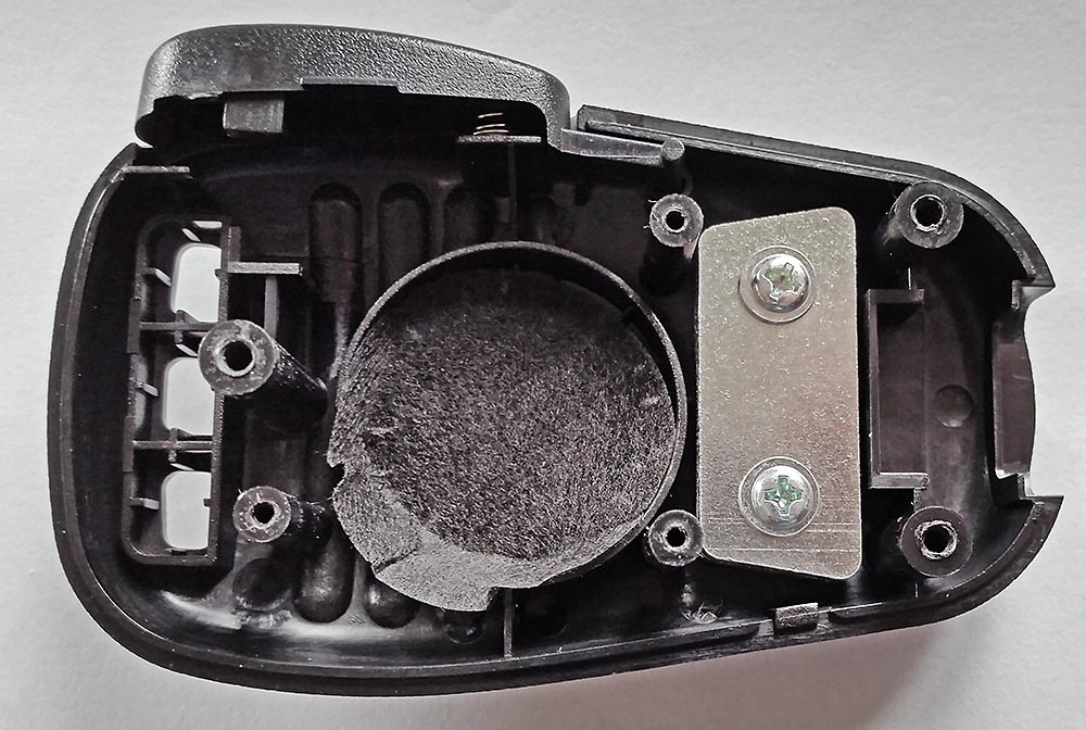
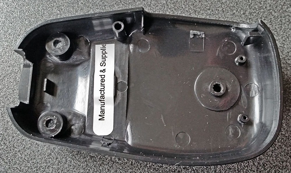
Opening up the supplied microphone and removing the PCB revealed these 2 slabs of steel in the body. The only function of these I could see was to add weight to make it feel more substantial. So I got rid of those. No point in carrying dead weight:
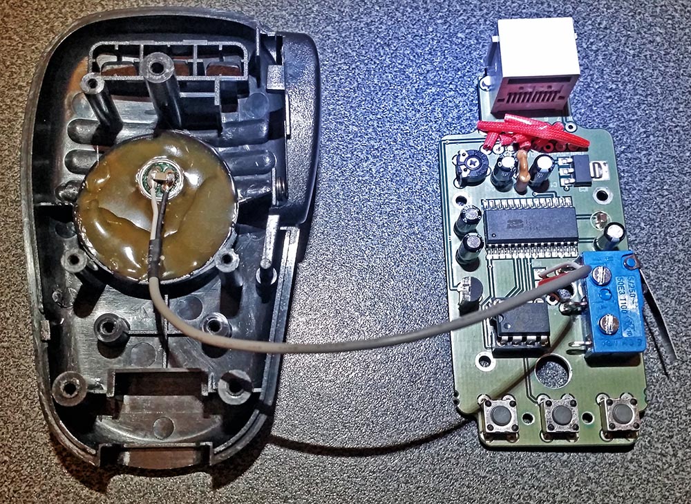
Next I hot melt glued the electret insert into the mic and filled up the void as the instructions said. Actually I filled more than the picture in the build instructions showed by mistake. Then solder the screened cable to the PCB and fit the IC and it’s ready to be assembled:
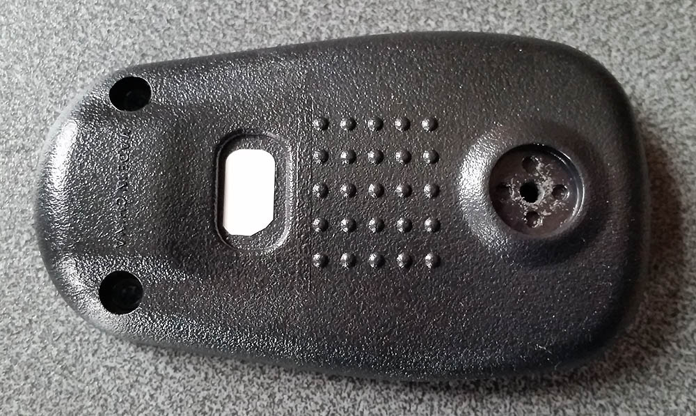
As the replacement PCB does not have the two position slide switch, there is the unused hole in the back of the mic. For this I just used some good quality sticky label material I have to hand.
One piece inside:
And one on the outside.(not pretty but functional):
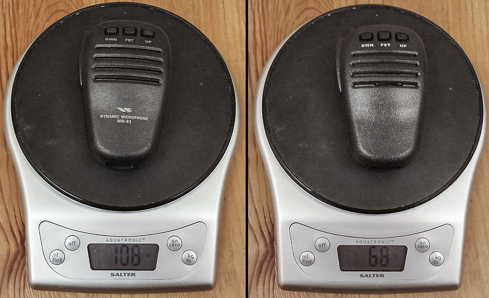
Once assembled I compared the standard supplied Yaesu MH-31 mic for weight against the BX-184 CQ parrot. A 40% saving in weight, I’ll take that:
I soon connected it up to the radio ready to go but there was no outgoing audio! What!? With several projects on the go I could do without time spent fault finding. What if I have cooked the electret soldering the capacitor on now it’s well and truly hot glued into place. Hmmm. Hold on, what was that pot trimmer for? I remembered when building it I couldn’t see any mention of it. A check of the circuit confirmed the obvious answer. It’s on the mic output to the radio. A quick check with the meter confirmed it was currently set to ground the mic line going to the radio. A quick tweak and we are back in business.
In fact the worst part was setting up to monitor myself. Eventually I had a reasonable system, FT-857D on 5Watts into a dummy load near the FT-897D with a 4mm banana plus as an antenna feeding into the sound card on the PC, with Audacity dealing with the recording. The recordings are not broadcast quality but are good enough for a comparison.
Here is a CQ call using the standard MH-31 mic:
Here is same CQ call live using the BX-184:
And the replayed recorded CQ call from the BX-184:
I might need some on air radio reports for final setting but it doesn’t seem to be clipping at all though does have a little more punch.
Can’t wait to try this out in a contest or SOTA activation. All in a great little kit well thought out and went together very well. The only small point is no actual mention of the trimmer function or setting which would be good as a reminder if nothing else. I know this kit is aimed at radio amateurs who should be able to look at the circuit and deduce why the pot is there so this is a very minor point in a great kit.
Edit:
I have since used this ‘in anger’ in 144MHz contests. The first contest I got some complaints about over driving and being wide (complainant was also wide to me for that matter!!). But I turned SSB mic gain down in the FT-817 and back at home I did turn down the audio output level on the microphone itself and did some tests between it and the standard MH-31. Subsequent contests have resulted in zero complaints but some good audio reports.
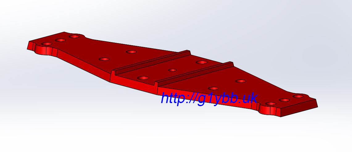
In order to facilitate the building of my backpacking lightweight 144MHz 9 element DK7ZB yagi with a friend I came up with this reinforced plastic element mounting plate.
The primary idea behind it was that it would make it easy to accurately position elements in the right position along the boom and also ensure the elements were mounted nicely perpendicular to the boom. This was the sought after benefit for my build, ensuring all elements were nicely parallel to each other and in the same H plane. Also it would allow easy use of specific element mounting methods particular to my variation of a DK7ZB 144MHz long yagi beam design. The mounting plate is specifically designed to work with 20mm square section boom.
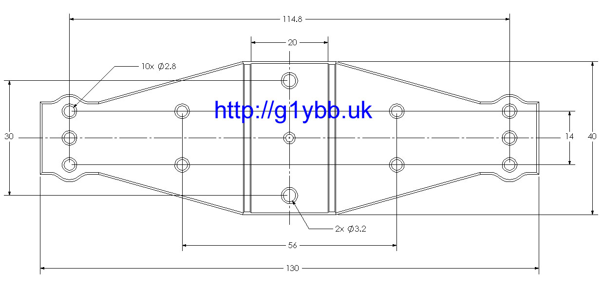
Here is the 3D design of the element mounting plate: And a dimensional drawing for suitability to other yagi build applications:
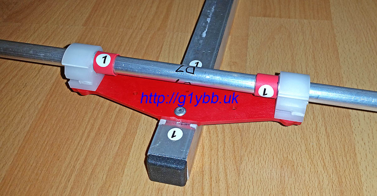
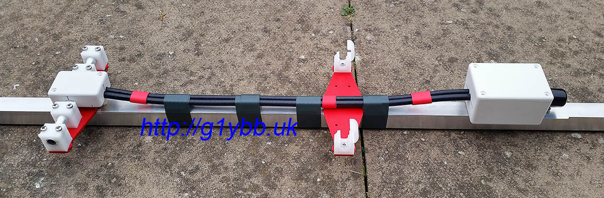
For my beam (linked at top) I was able to use this to mount both parasitic elements and the custom driven element:
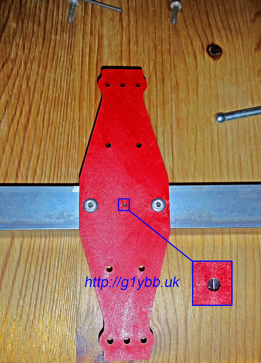
The element mount plate has location ridges underneath to align perpendicular with the 20mm square boom and has a small central sighting hole to align with a marked up boom for element centreline positions:
Two fixing holes are provided to fix the element mounting plate to the boom. They are sized for 3.2mm pop rivets but can be easily drilled out for other sized bolts or rivets. The element mounting clip holes provided can also be easily enlarged. They are supplied undersize for M3 deliberately so that an M3 bolt has to be screwed into them thus providing a precision centre aligning of the bolt and hence element clip mount.
Here is a video of the element mounting plates in action:
As I was planning to resume 144MHz contesting but this time full backpacking style I wanted a decent beam that was suited for repeatedly assembling and disassembling. I have a Cushcraft Boomer and also a pair of homebrew DJ9BV yagis but neither are really ideal for the job. After nearly two decades away from radio yagis have moved on and researched showed the DK7ZB yagis were very popular. His designs seemed ideal for my purpose.
I settled on the 9 element long yagi as it is not too long but with decent gain and also has a good flat SWR curve. The RSGB Backpackers section we wanted to participate in only allows one antenna so stacking shorter yagis was out.
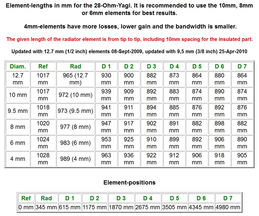
The dimensions are available on Martin DK7ZB’s site:
I went for the 10mm elements as a compromise between size and weight and best performance. I was also able to find 10mm clips to suit my intended design.
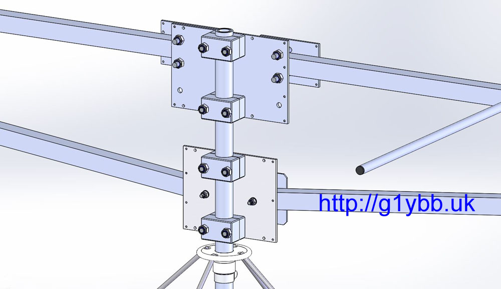
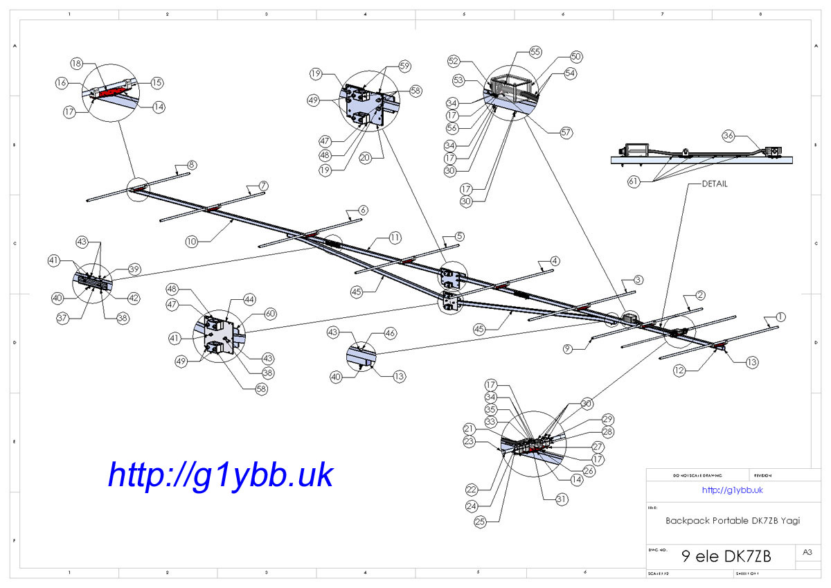
You can buy some of the DK7ZB yagis ready made and also in kit form, but I didn’t really think the parasitic element mounting methods were ideal for repeated building especially in cold weather. Also the driven element was a problem as it’s not ideal at all for disassembly. There was one example of a driven element designed for taking apart on DK7ZB’s site but I couldn’t find any parts like they were using. I was already building my own lightweight portable mast so I decided I may as well design the yagi from scratch too. So I modelled the full antenna down to every nut and bolt in 3D CAD software. This enables me to know exactly what materials I need and also predict pretty accurately the weight, bearing in mind I plan to backpack this up hills:
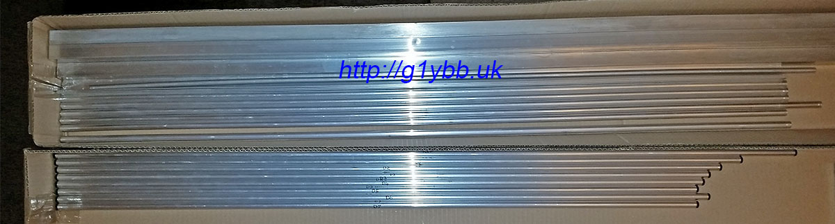
To source the main raw materials I found that it was cheaper to buy from https://shop.nuxcom.de/ in Germany than anywhere I could find in the UK! I went for the 20mm square boom and 10mm elements. My 3D CAD model told me I wanted two sections of boom 1.72m long and one section 1.62m long. (After ordering I noticed that is the same lengths Attila uses in his 9 element kits!) I didn’t go for a kit as there were several parts in the kit I didn’t need and I wanted to order a few spares of the elements just in case I cocked up some of the cutting. Nuxcom sell the boom in 1.5m and 2.0m lengths but the 2.0m lengths cost more than double the shipping, so I asked Attila if it was possible to buy 2.0m lengths but have them shipped in two pieces, 1.72m and 28 cm lengths. He did this for me at no extra cost which is good service. The offcuts would be useful for doing tests later.
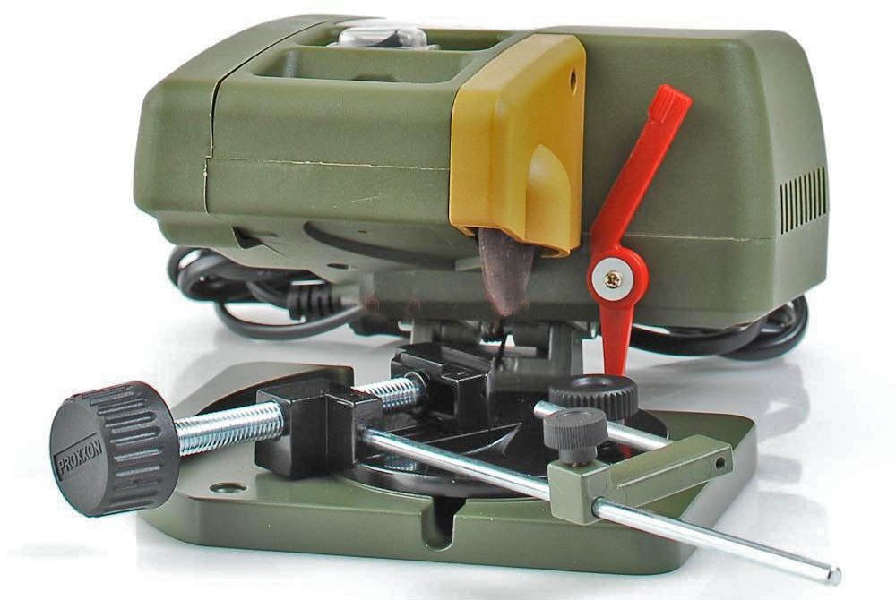
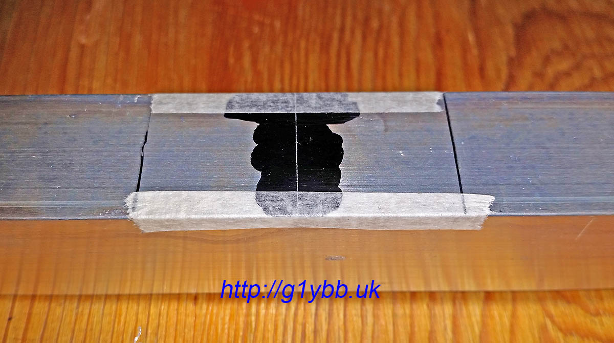
First building task was to cut the parasitic elements to size. Although I’m pretty good with a wood saw I’m a bit rubbish with a hacksaw and I didn’t want to use a pipe cutter as certainly for the driven element I needed no deformed ends to the tube, so I managed to borrow a mini circular disk cutter like so:
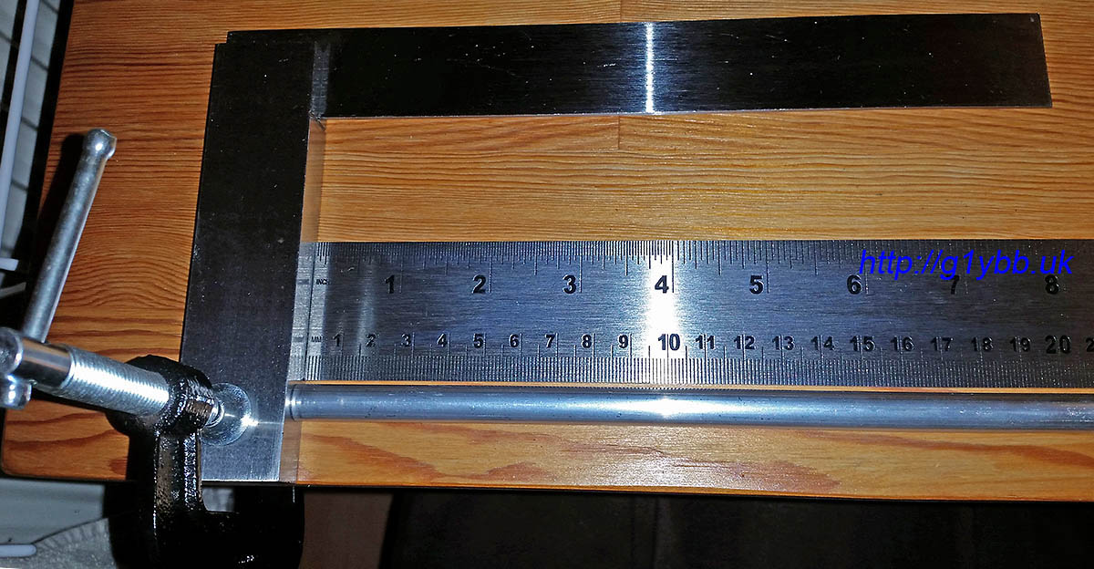
With this I was able to make nice square cuts. To measure them I used a metre ruler (tape measure for the reflector-checked against the metre rule first) butting both up against a stop to get an accurate measurement. I checked that the first mm was a true mm before starting as some rulers have a dubious first mm:
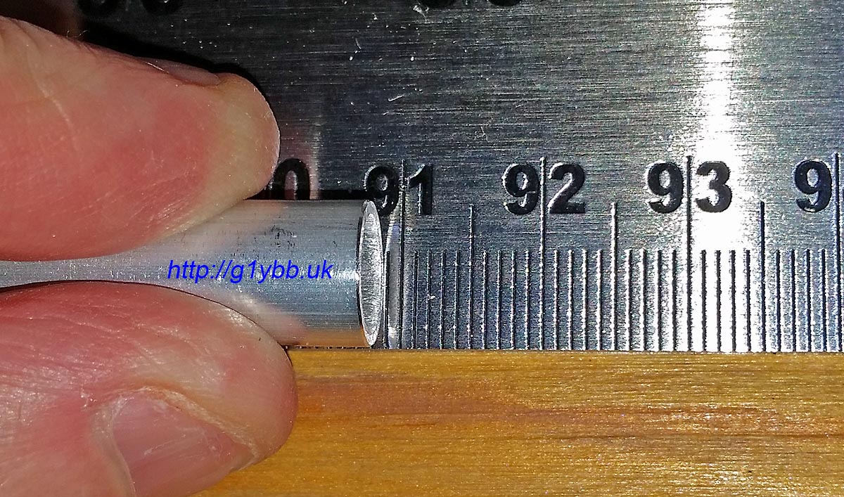
And checking D2 (ever so slightly short if anything by a fraction of a mm):
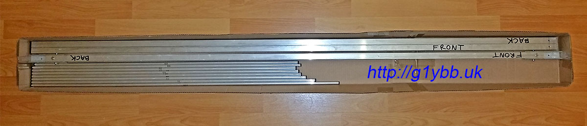
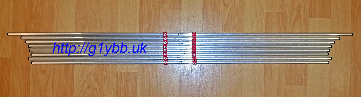
After cutting the parasitic set I fitted end plugs from Nuxcom for a nice finish. (Elements in bottom box, spare elements and boom sections in top):
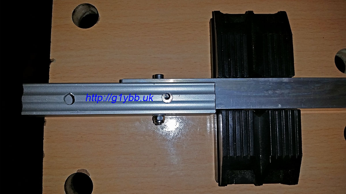
Next to assemble the boom. I bought the Nuxcom boom joiners and I must say they are very well recommended. The fit onto the 20mm boom sections is a snug push fit and the extrusion is thick enough to be strong yet still light. I got them with the M4 bolt and wing nuts. The one thing I didn’t like so much was the massive hole for M4 which was 6.5mm diameter. However, once I modelled up the joiners and dropped them into the antenna assembly I could see that a 4mm hole at the top of the 6.5mm hole would be pretty much bang on centre of the boom, and mean the boom could not move up in the joiner. I also added a vertical bolt on each side of the joiner too as shown below. That meant the boom section was forced into the joiner tightly ready to drill the holes. I drilled from each side, using the 6.5mm hole as a stop for the 4.0mm drill bit:
The above picture is showing the boom joiner fitted to the centre section. Both joiners are fitted to the centre section and will stay there permanently so I have used socket cap heads and nylocs, all stainless steel, bolts cut to minimum length. (The four supplied wing nut bolts will be used to attach the end sections on the hill top). With both joiners fitted, the centre section then is pretty much the same length as the outer sections (by design). I also bought the square boom end caps from Nuxcom to finish them off nicely:
The boom was then assembled in my hallway and the centrelines of the element positions scribed on. I used a tape measure masking taped to the boom to ensure it never moved and starting at the 100mm mark on the tape measure to eradicate any errors from the tape measure hook end.
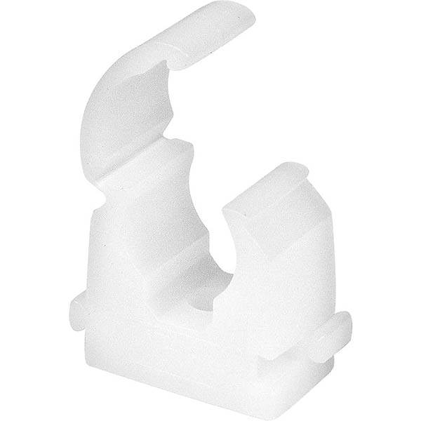
The element clips I needed to find something that was quick to mount the elements and remove them again. The typical single bolt through the centre of the elements I didn’t fancy as it was a bit fiddly especially with cold hands on a windy hill top. My friend found these 10mm pipe clips that were ideal. Snap in and lock, and easy to open again to remove the elements. They will have a finite life but my test piece has had dozens of cycles and they come in a bag of 100 for under £6: Another plus point of this is the element centre is a reasonable distance off the mounting surface which means I had good scope for getting the driven element to be on the same plane as the parasitic elements. I just need some suitable plates to mount these on nice and squarely on the boom. My friend offered to injection mould me some rather than my trying to accurately drill out several plates exactly. So I modelled up a mounting plate to be made from glass fibre reinforced nylon which is extremely strong and stiff for its weight. The image shows the underside. The two ridges are to locate on the square boom:
Soon in the post came a parcel of element mounting plates. We decided riveting them on was a secure and lightweight fixing method. The two location ridges on the bottom had a slight amount of play when offered to the 20mm boom which of course would be amplified by the approx 100cm elements so I fitted two tiny strips of masking tape which made the plates a perfect fit. Once the rivets were in it doesn’t matter if the masking tape decomposes away:
The small hole in the very centre of the element plate is a sighting hole to align the element in it’s correct position on the boom. This was used to line up to clamp the plate on for the drill of the first rivet hole:
Once the first rivet was fixed, the clamp was no longer needed and the 2nd hole drilled and riveted:
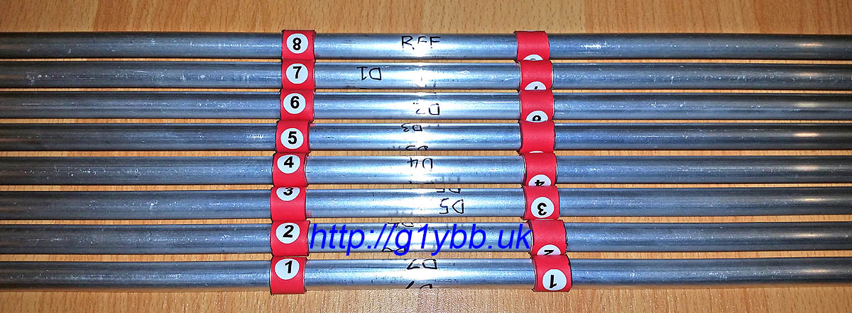
Then a simple case of fitting the 10mm pipe clips and snapping in the elements in the right place centred on the boom. In order to easily locate the element centrally on the boom with out any time consuming I fitted to each element a piece of adhesive lined heatshrink to be positioned between the clamps. I also added some marking numbers for the 8 parasitic elements, numbered 1 to 8 from from to reflector:
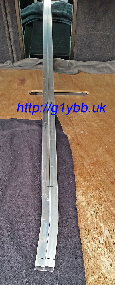
Now the easy bits are done, time for the driven element. This was the biggest head scratcher on how to make it suitable for repeatedly taking apart and assembling. I needed to come up with a method that both left the electrical connections to the driven element halves but also enabled me to remove them for transportation. This meant a split in each half of the driven, but how to attach it?
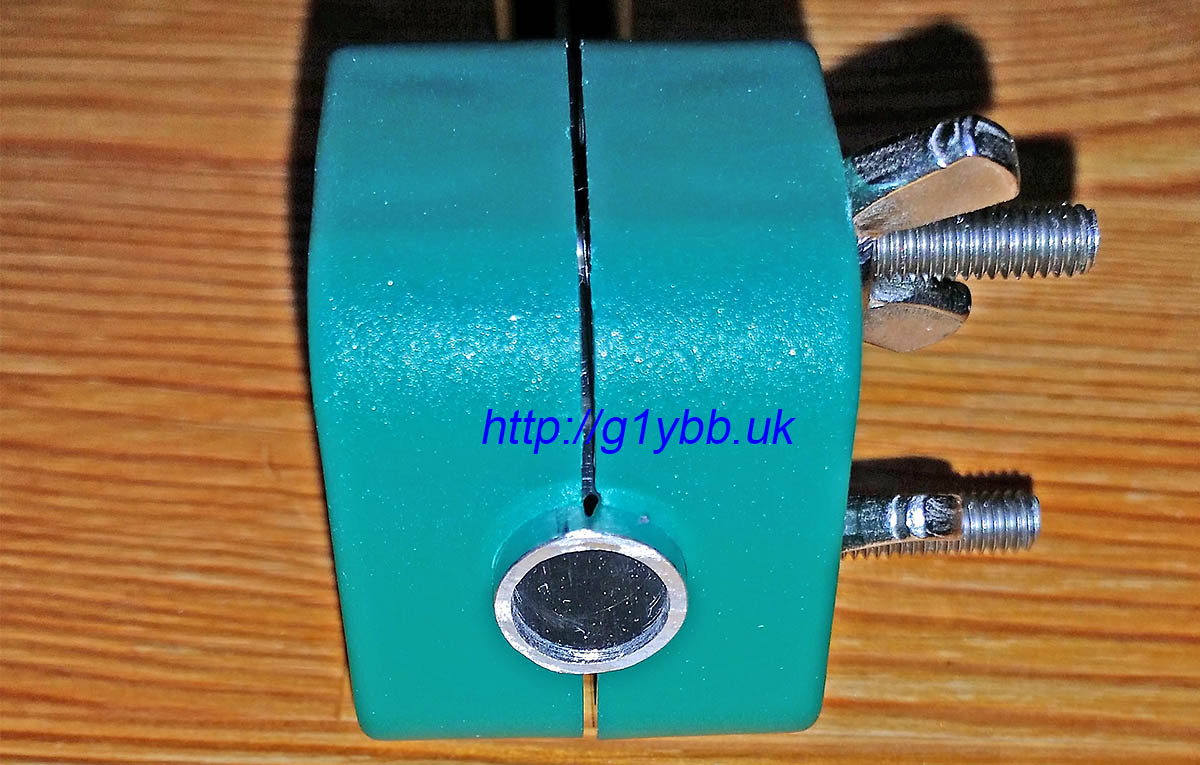
I decided to come up with a system of employing a ferrule in the driven to join the two halves. With some custom made parts it would also be mounted on the same element mounting plate as the parasitic elements and is the reason the element plate is larger than a typical one, although that was also good for rigidity and build accuracy.
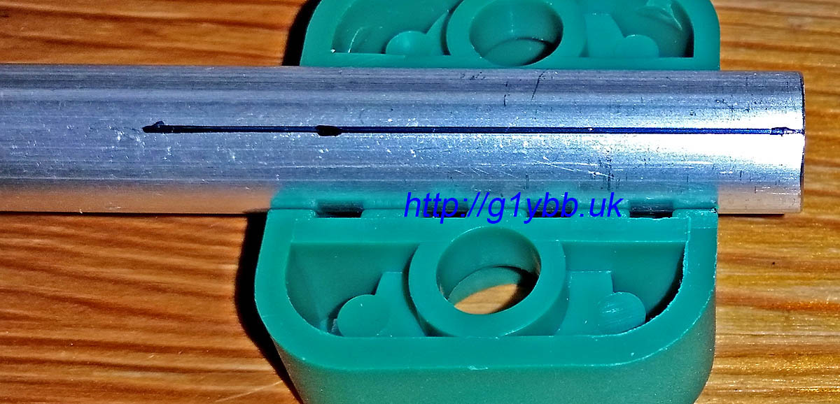
When I ordered my 10mm element tubing from Nuxcom I also ordered 1 metre of 8mm tubing to do this. But there were two issues with this. The first was this was the only piece of tubing that arrived with a bend in it. If I had planned to use it as an element I would have had to reject it. As it was I could cut out straight parts to use but the 10mm diameter 1mm wall thickness elements have a bore of about 7.92mm and the 8mm tube an outer diameter of about 8.10mm. No chance of a fit. Out with the calculator and it soon transpired 5/16″ should be a perfect size. I bought some T6 grade aluminium from eBay and it was a perfect fit. Sliding with no slop at all.
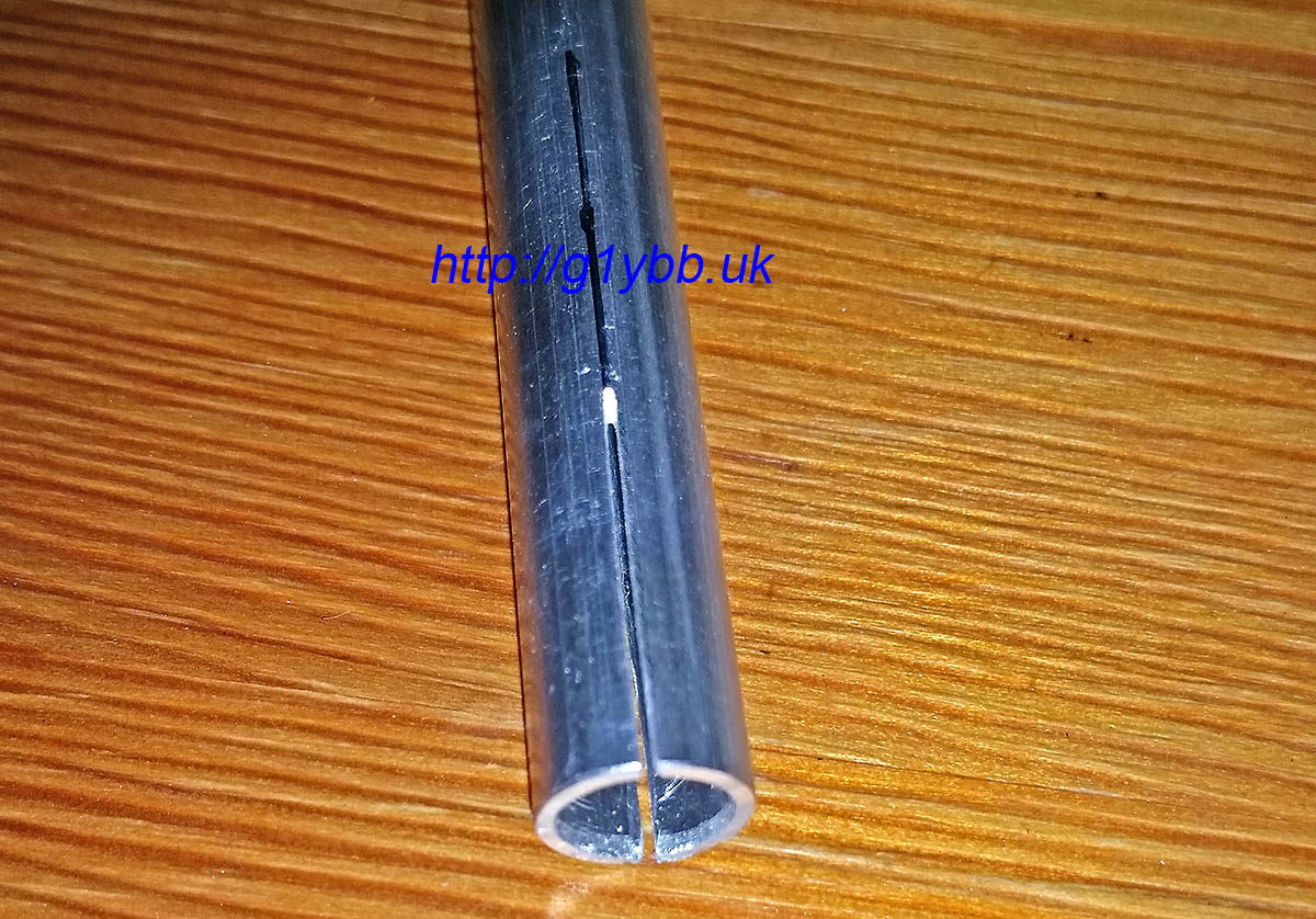
To cut slits in the 10mm tube to compress it with clamps to grip the ferrules I used two 10mm element clamps to mark a dot each end and each side of the clamp and joined them up to make cut lines to follow:
I’m not fantastic with a hacksaw to be honest but using the element clamps above to hold the tube in the vice I was able to cut (from both sides) fairly neat slits with a junior hacksaw (I wanted thin slits):
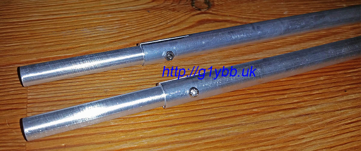
Then it was a case of fitting the ferrules into the outer halves of the driven elements and adding a screw to maintain a good mechanical and electrical grip:
Next to feed that driven element. I decided to straighten out the feed match to take the feed point a little closer to the centre of the yagi. I’m using WF100 75ohm coax which is fairly low loss for its size, and is not too big or heavy. Its claimed velocity factor is 0.85 so I worked out the length as so:
300/144.300 = 2.079m full wavelength
2079/4 = 519.75mm for quarter wave
519.75 x 0.85 = 442mm
DK7ZB gives a length of 440mm for this velocity factor, but I notice all his lengths are in multiples of 5mm so I wondered if he did some rounding down? I hope so!
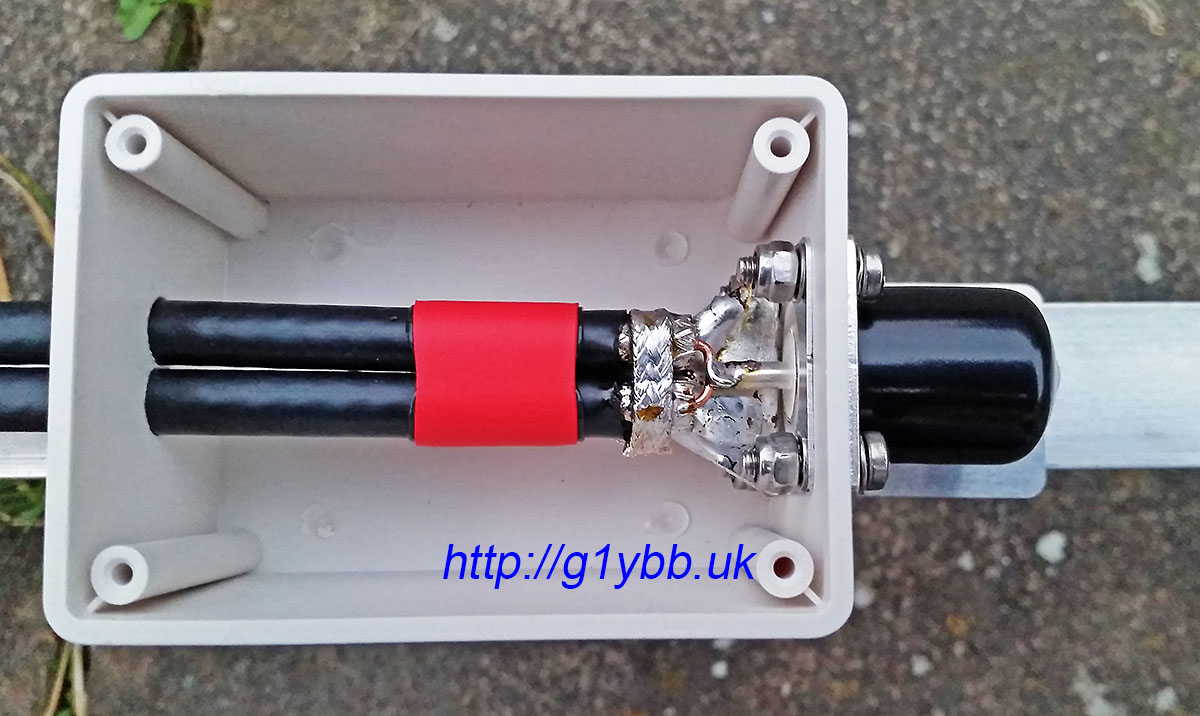
This is the length of the braid. I hate stripping and cabling up coax so did all I could to avoid twisting bits of braid about. I cut the braid and dielectric off square and about 5mm or so of the outer jacket to reveal the braid. With a very large tipped iron of unknown wattage I was able to tin the braid nicely with no apparent melting of the foam dielectric. I then made a small tinned copper plate to bolt to the N-type socket and solder to the braids making a good earth. For good measure I added a loop of braid from some RG223 soldered all round. Then made the inners as short as I could and soldered to the N-type:
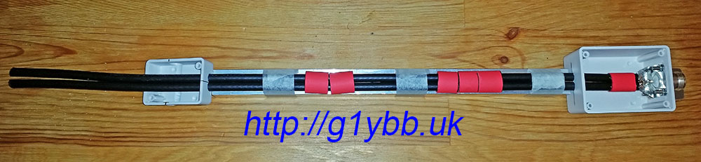
To tame the annoying curling coax I found yet another good use for the short boom offcuts I asked Attila to include. I taped the coax out straight to measure the 442mm finished length:
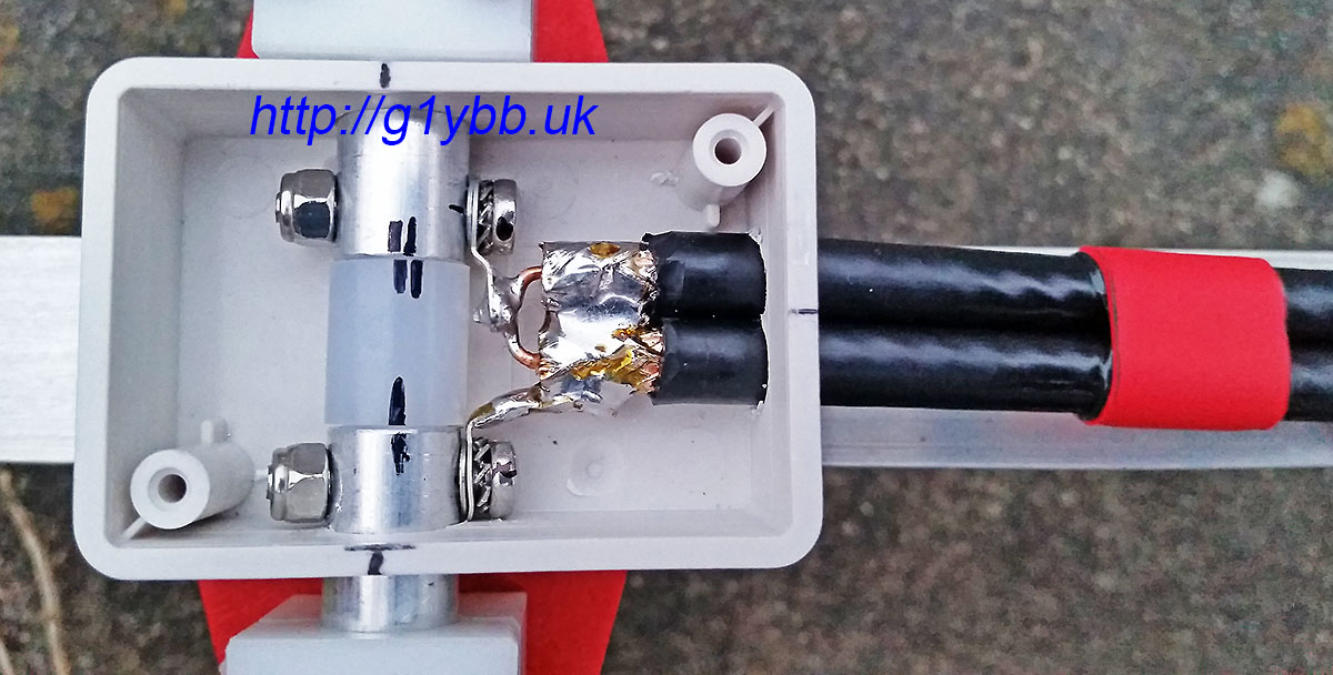
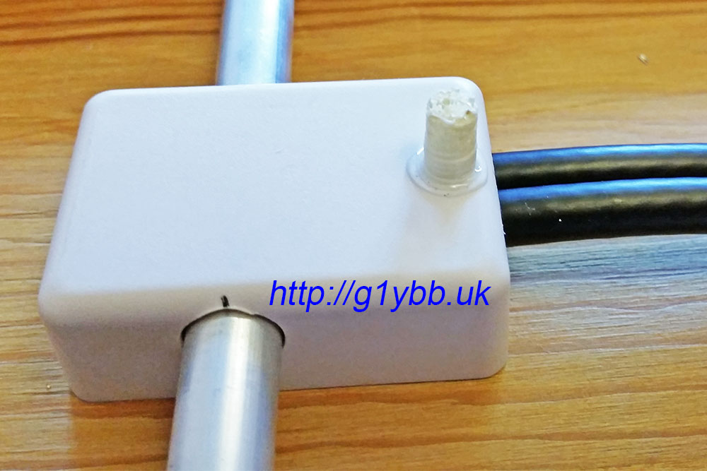
You can see I am using red adhesive lined heatshrink to keep the coaxes tidy and together. In the picture above the tiny box for the driven element connections is threaded on ready for the stripping and fitting of connections. I used a similar method as on the feed end with some copper sheet to join the braids and solder tags to connect to the element halves. This was a very fiddly job but hopefully worth it keeping the connections as short as I could manage:
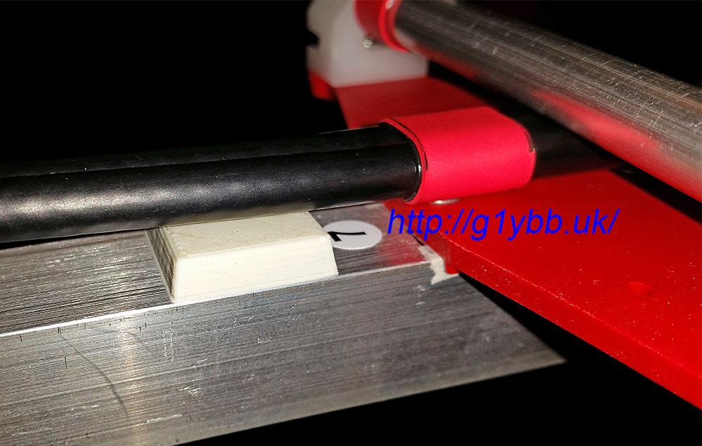
To support and space the feed off the boom as recommended by DK7ZB (although this is going to be used for QRP almost exclusively) I got some ABS spacers 3D printed which I placed in position and then wrapped tightly with insulation tape. The idea is to keep the coax off the boom (which it is miles away from) but also as far away as possible from the element plate rivets but also as far from the element the coax passes under:
The driven element box is supported solely by the driven element inner pieces themselves, but I added a very small 3D printed pillar to make everything secure:
Here is the feed match finished:
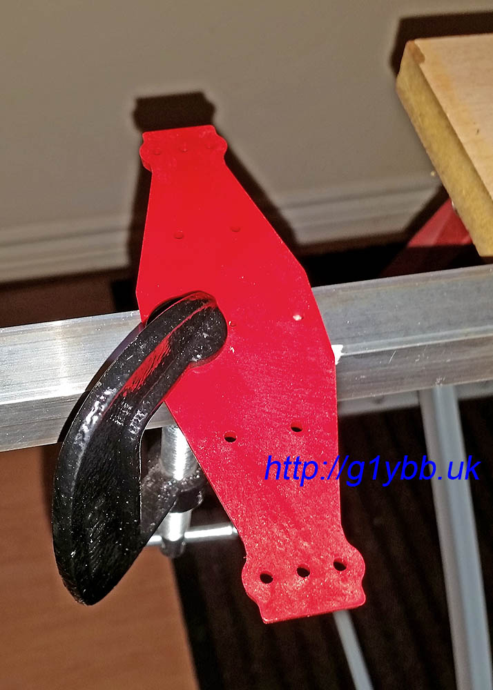
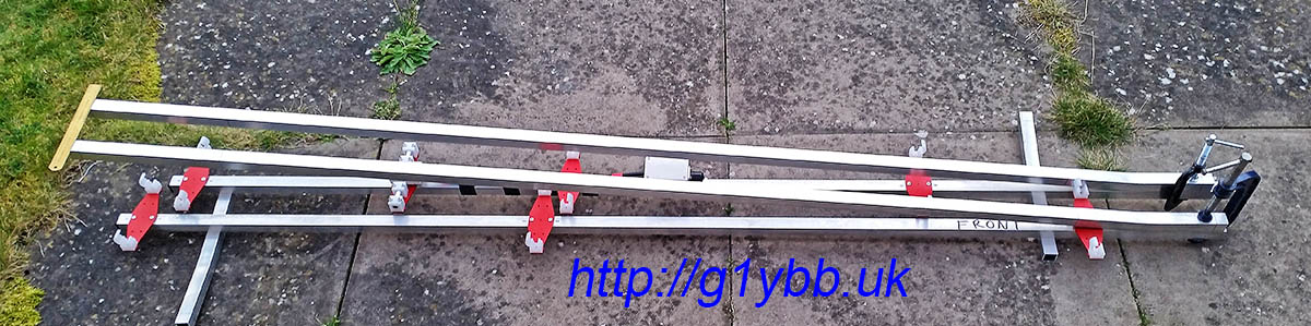
As I plan to use this on a lightweight mast section only 20mm in diameter I didn’t think the usual U-bolt clamps would be able to create enough friction to stop the beam spinning on the mast without being so tight to possibly crush or weaken the 20mm ali mast. I bought some plastic 20mm clamps for large yagi elements from Nuxcom to try but they do not have enough friction. So I drew up some half round clamps to be made out of aluminium:
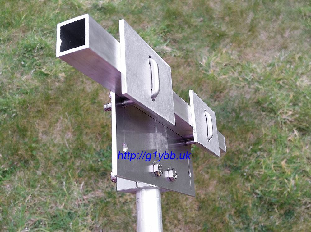
I used a small 3mm aluminium plate in usual manner and bought some 20mm square U-bolts for the 20mm boom itself. As the 20mm boom again is quite small for a long yagi I was again concerned about over tightening the U bolts and creating a weak and potential failure point so I added some small 3mm aluminium plates to allow it to be tightened up nice and tight without any fear of crushing the boom. Here is the finished boom to mast mount. (The two unused holes visible are there to use with the lower 20mm boom mounting holes for a 25mm boom yagi I have):
I used a similar arrangement for the boom support to mast fixings, the aluminium clamps and a slightly smaller aluminium plate. Just a simple M4 bolt per half of the boom support and another plate to help strengthen it all up. The intention is that the boom supports will also help offer a little sideways strength against the wind as well.
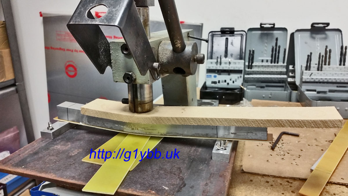
To bend up the boom supports I first tried to bend some 20mm square section (same as the boom) in my workbench jaws (seen above in the first picture after cutting the elements). They were not strong enough to bend it! Note this is not a proper vice as such, more of a drilling and cutting bench with jaws. I then thought I might use a bottle jack to apply the force but couldn’t think of anything solid I could jack onto. Then I remembered we have a small 3000lb lever press at work used for punching small holes in sheet metal. I soon made up a jig using a 10 inch square of ¼” steel with some small aluminium blocks and I used the spare offcuts (yet again) to work out the right amount of packers below the centre to give me the bend angle I needed:
I used 10mm MDF to spread the load from the press and protect the 20mm square tube and a strip of bare FR4 as a bearing and protection to the underside. Once tests were done I quickly and easily put the bends in the actual supports:
Checking the bends are matched:
Then just a case of offering them up, drilling holes in the right places and fitting. Finished!
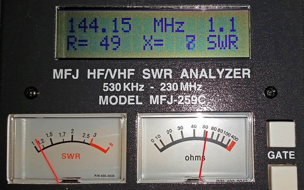
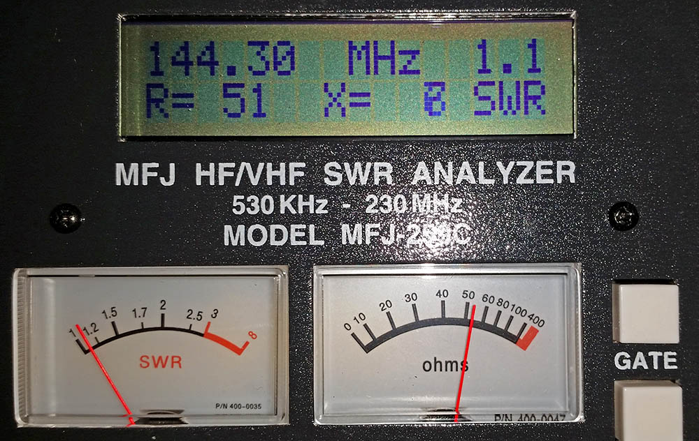
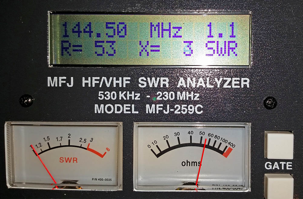
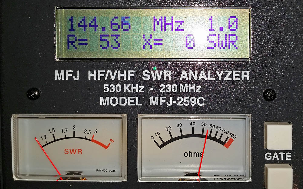
Now for the moment of truth, how does it measure on the antenna analyser? Well to me it looks to be best match at 144.660MHz but is showing SWR of 1.1:1 and 51Ω at 144.300MHz so I’ll take that thanks:
Here is a real time video showing how long it takes to assemble the elements (I have not shown the boom assembly as nothing unusual or new about the boom assembly):
Only job left now is to take this up a mountain top and do some contesting!
Edit: I have done my first contests with this now and it seems to work really well and I got good reports all round. Even with a low loss feeder the radio was not indicating any SWR reading at all on transit. I have come 2nd and 1st in the low power section of the first two UKAC contests I have entered so I am really pleased with the way this yagi performs. It ‘feels’ even as good or better than our 2x 19 element MET yagi array.
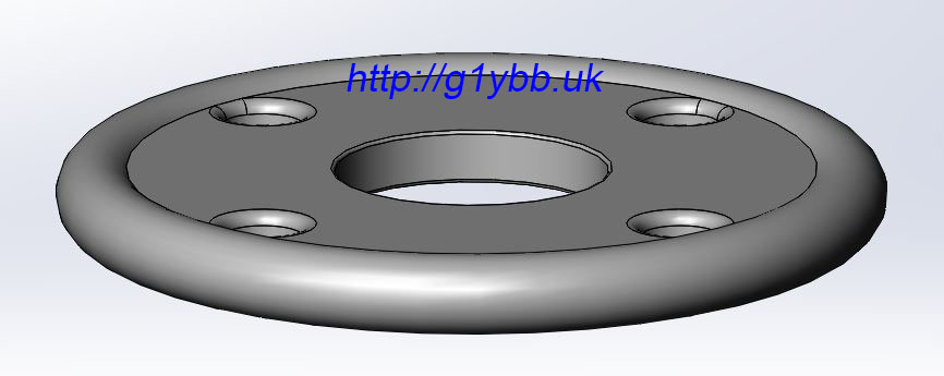
When I made my lightweight aluminium portable contest mast I designed up an ultralight strong mast guying ring to use that was both strong and light. I designed it for my friend to injection mould in a fibreglass reinforced plastic that is really strong. The material is so strong I could not damage a 1.5mm thick long credit card size sample by hand even across the edge of a table. All I did was hurt my hands.
So with one eye on weight and one on strength this is the design I came up with. The design criteria was that these rings would hold up a mast carrying a decent sized 144MHz long yagi with at least a 5m boom on an exposed mountain summit in winds at least as strong as the tent will take but also be nice and light and small. They are very similar to many others you will see (there’s only so many ways a guy ring can be designed), but this is only 61.5mm outer diameter and 14.2 grams in weight:
I went for the simple 4 holes rather than extra holes for 3 point guying that some rings offer as it’s easy enough to just use 3 of the holes. Rope holes are 5.8mm which is plenty big enough for 550lb paracord or other ropes you would use with a lighter weight mast system. The centre hole is 20.5mm sized to fit the top section of my mast. For the lower thicker section it’s easy to open the centre hole with a step drill, in my case 26mm. 30mm is about as big as I would open it too though to retain full strength.
When the rings arrived in the post the first job was to test it for strength. I figured I would make a good test load. Just needed something to hang off and give it some welly. I am a good 170lbs, probably more with boots and big coat on. The rucksack is full of 2 litre bottles of water, probably a good 30lbs more easy. So about 200lbs bouncing weight on the guy ring. This is on a very short length of paracord. A longer length will absorb more shock like a climbing rope does:
Once I was happy with them fitted to the mast and the guy ropes tied on:
And in action:
These rings will also be very useful for SOTA activations where the very ultralight commercially available rings may be a little brittle without adding a noticeable weight penalty. Used for a fishing pole mast the mast will break long before these rings will!
I mentioned that these could be ideal for other radio hams doing SOTA activations and other portable operations wanting a very strong but lightweight guy ring he has made these available (pretty much any quantity) on his website: https://dura-id.store/product/lightweight-mast-guy-ring
Having just finished making a lightweight aluminium portable antenna mast for backpacking VHF contesting I wasn’t really happy with the initial way we were tying down the guy ropes.
Typically I have tied off guys that don’t have tensioners with several half hitches. These are quick and easy but they are hard to tie tensioned properly and I have lost two 19 element MET yagis, a Yaesu rotator and an aluminium scaffold pole when one guy worked loose on a windy day. I didn’t want to use tensioners on this setup as they can work loose and we are going to be operating from a tent and won’t see any loose guys until too late most likely. Also I’m using for this mast lightweight paracord which is meant to be good to 550lbs breaking strain, but I am wrapping that around fairly sharp edged aluminium angle guy stakes which might create a weak point on the paracord. The mast is not massive and I have 2 sets of main load bearing guys but I want this to stay up on exposed windy Welsh mountain tops.
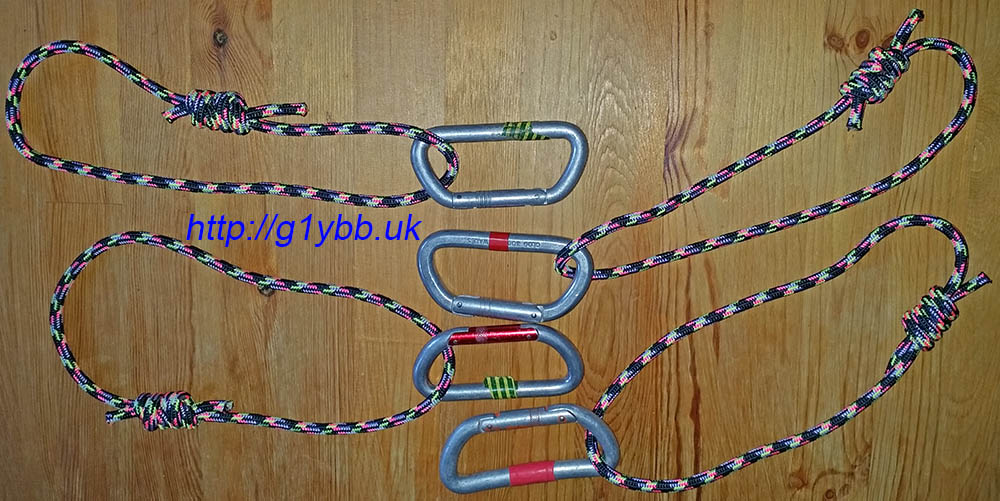
So I thought a round bar would be a better shape to tie the guys to and a clove hitch would be a good start knot as it can be tightened up. For the round bar I thought I would use some of my old climbing karabiners. And to attach those to the guy pegs I would use some small sized climbing rope about 6 or 7mm and use a clove hitch to quickly attach those to the pegs.
Here are the karabiners and rope loops. The rope loops were made from about 1m of rope each and a double fisherman knot used to make the loop:
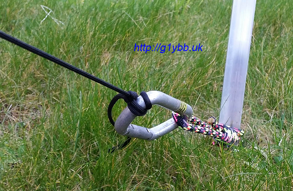
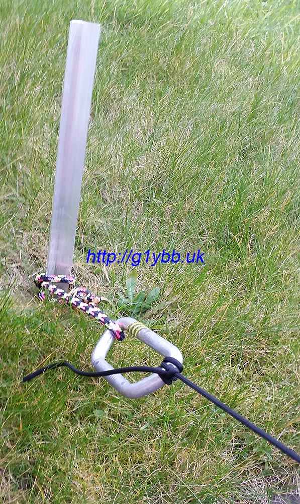
Once the karabiner was fitted to the guy peg it was very quick and easy to make a clove hitch and slip it on, tension, then lock off with a couple of half hitches:
This adds an extra 381grams to carry but I think it will be worth it in the long run. I could probably cut that down with newer smaller and more lightweight climbing karabiners (I’m not going to risk the cheapie ebay style mini ones) and probably a smaller rope would be OK to use:
This is one way of many options, I’d love to hear your methods and tip and tricks!
(email explained on welcome page)
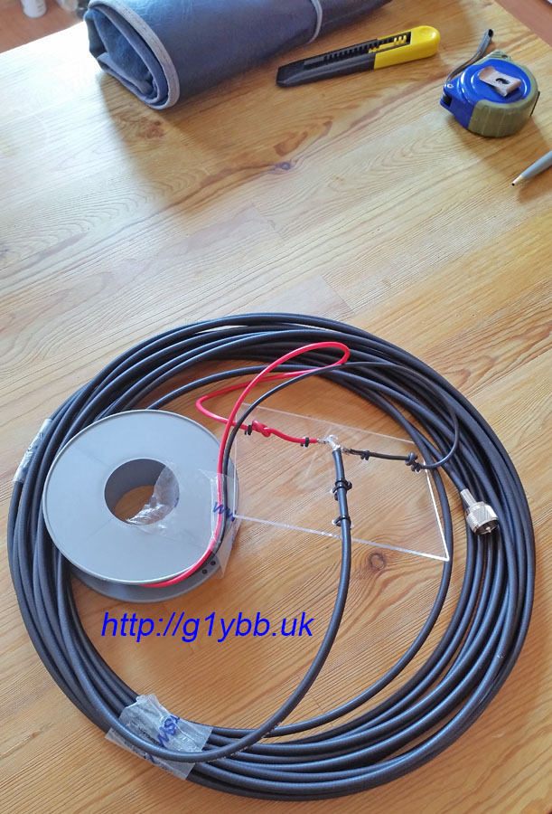
My portable HF 3 band linked dipole for SOTA activations I like to pack the wire away on a spool rather than a kite style wire winder. I find the figure of eight loops put kinks into the wire and I just prefer the wire to lie straight.
Since I made the dipole I have been winding both halves of the dipole onto one shared spool like so (picture is an older dipole but the spool is the same one I now use on the portable dipole):
I use this spool as it’s the smallest I have to hand and has the capacity for both wires including their integral guy strings each end. This is OK in that it keeps the wires lovely and kink free but it takes a while to wind them onto the spool, and bringing one half of the dipole to the other invariably involves unhooking it off every tiny thistle or twig on the ground. Also the two halves love to tangle together.
My dipole (described here) is for 20m, 30m and 40m with small bullet connectors for the links and is made from insulated 16/0·2mm wire with 3metres of 3mm nylon guy line attached at the end of each half.
So I decided to model a smaller dedicated single wire spool to separate the wires and make deployment and packing away easier and faster. This would be 3D printed by my friend Paul so the design needed to be suitable for that, ideally with no time consuming support structures needed during the printing. It would be in ABS so a two part (identical halves) design was used which would be cemented together. The cement works like a weld essentially melting the two parts together. Loading on this part is very minimal anyway.
This is the design I came up with:
The design features were to be:
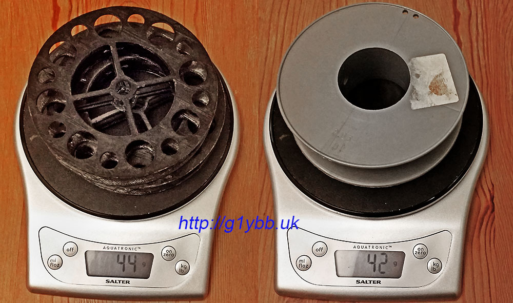
Lightweight. I wanted the two spools to be equal or less weight than the existing single grey spool. I am always aware of ‘feature creep’ upping the carry weight. A large central drum and shallower cheeks keeps weight down, as do the weight reducing holes.
Function. Obviously I need it to take all the wire without overflowing but not have so much capacity I was carrying dead weight.
Usability. I wanted to make it easier and faster to use. The larger internal drum size means more wire wound per revolution and the cross members in the sides are sized to allow a gloved finger from each hand to fit in quadrants 180° from each other to make a simple hand winding action. Additionally the larger weight saving holes were sized to allow the plastic guy locking buckle to pass through to make starting the winding up of the guy very easy.
Bonus features. I realised when adding the weight saving holes that a good airy pattern of holes would greatly help with natural airing and drying out when packed away wet. I also added some internal locating lugs that would self centre each half during the cementing together process (a request from Paul after the prototype build).
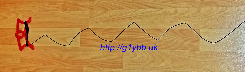
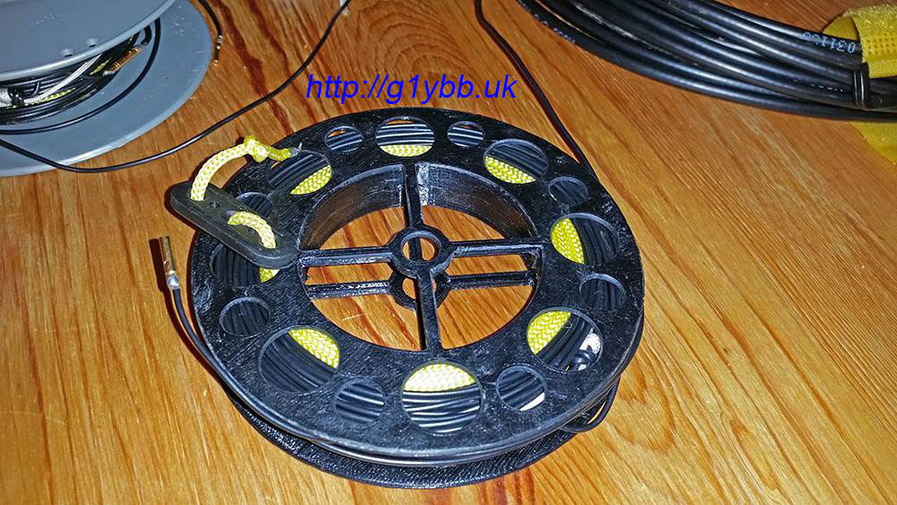
The 2nd version soon arrived and was tested with the dipole. It was definitely much easier and faster to wind up the single dipole half which fitted nicely in the spool capacity (that’s an open 20m to 30m link sticking out):
Deployment is extremely fast as the spool is small enough still to use a thumb and finger of one hand as an ‘axle’ on the centre hole each side (sized to take a pen or pencil for when it’s too cold for dexterous hands) and as I can now deploy each half where I need it immediately with no tangles I’d say deployment is between 2 to 4 times faster which is appreciated when the wind and rain is biting.
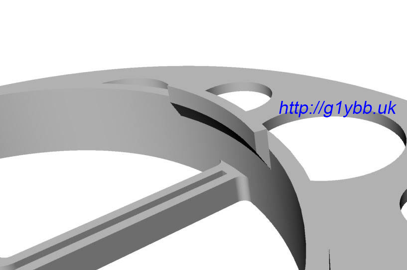
Paul has made a small improvement to the design for printing purposes. My location lugs had such a small surface area they did not have time to cool down before layers so he has extended them lengthways but removed the vertical part of the lug to keep the volume (and thus weight) the same:
Here are a final pair to make one spool fresh off the 3D printer:
The final weight for the pair of finished 2 part cemented up spools is 44grams. 2 grams over budget but I can live with that for the much better overall system:
SOTA HF dipole ready to roll, literally:
Quick demo showing deployment and packing away:
If anyone with their own 3D printer is interested is making use of this design Paul has made it available on Thingiverse and Youmagine.
(Obviously your wire diameter and lengths will dictate suitability)
As I was looking to resume my contesting activities but SOTA style backpacking (for the RSGB backpackers contests) I needed a lightweight portable mast that is strong enough to stand up to some Welsh Mountain top wind and hold up a decent yagi. I looked around the Internet to see if anything was available already but nothing seemed to fit the bill for me. So I decided I would make one myself.
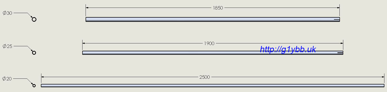
The biggest problem I had was finding tubing that was available and would telescope inside each other. The UK still mostly stocks imperial sized tubes, and each size seemed to be a fraction of a mm too big to fit in the next size up. I did find some metric tubes with a 2mm wall thickness in 5mm diameter step sizes. The sizes were 30mm, 25mm and 20mm. I would have preferred the smallest to be a little bigger like 25mm but I figured it would be OK well guyed.
I wanted the mast to be telescopically erected like I do with the SOTA fishing pole mast so I worked out how high I could reach and modelled up the mast in 3D CAD to find out what the end result would be and what length tubes to order. Also so I knew what lengths and total length of guy rope to buy. Also by applying correct materials to each item and modelling them exactly it enables me to know with pretty good accuracy what I am letting myself in for weight wise for the entire system:
I decided to make the top section longer, both to get a little extra reach and to have a little extra to leave the antenna fittings permanently attached to reduce assembly time. It’s a little long to carry at 2.5metres but should be OK:
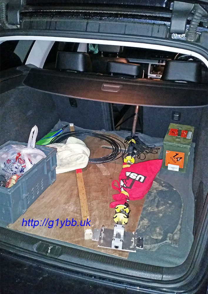
It does fit inside my Passat estate very nicely though:
Using these lengths and with 300mm of pole overlap a maximum height of 5.65m is achievable. Removing the thickest section enables me to keep it to the 4m limit nicely for backpackers and save about 1kg of weight:
To clamp each section I planned to slit the ends in the normal way and use jubilee clips (worm drive hose clamps). Talking to a friend he suggested a different type of hose clamp with a bolt so it would ultimately be stronger. eBay came up trumps and I ordered three clamps like this:
Then I just had to cut slits for the clamps to compress the tube down. The difference in diameters are 1mm so I needed to lose at least 3.141mm off the outer tube. Four 1mm hacksaw cuts did the job. The heavy duty hose clamps are nice and wide (20mm) which helps increase the clamping area:
I wanted 3 sets of guys for the full height mast, one at the top of each section. I would be using 4 guys rather than 3 as it suited my expected erection method. No commercially available guy rings I could find would fit so I discussed options with my friend and he offered to injection mould me some from a very strong and light plastic which would be perfect. I modelled that up and sent him the design:
More details and load test of the guy ring are here. As two rings would be on the 20mm section it would be moulded to fit that and I would enlarge the bore for the next section down with a step drill.
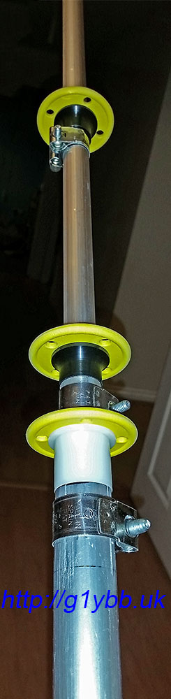
To sit the guy rings nicely I added some nylon bushes to hold them above and clear of the hose clamps and also to enable practically friction free rotation. I was able to find online an existing bush to fit the 25mm pole but not the 20mm pole. Luckily I have another friend who works in a tool room who turned me up what I needed in some nylon.
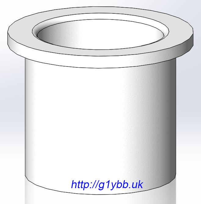
Commercially available bush, 25.5mm bore for mid section:
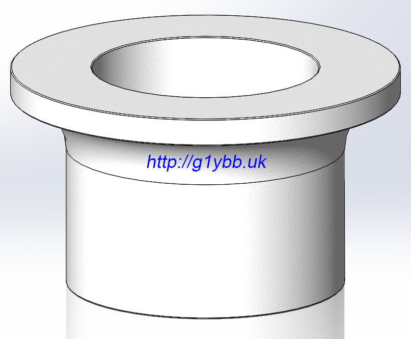
Custom made bush for 20mm top section:
Section view of bush in use (bush in blue). The idea of the bushes are they lift the guy ring away from the hose clamps to reduce risk of guy ropes snagging on the clamp, add a low friction intermediate interface between the aluminium tube top or the hose clamp and offer a flat surface for the ring to seat on to reduce the chances of the ring jamming diagonally across the pole:
For the guys themselves I looked at various ropes and cords available and decided on 550lb paracord. It’s light and strong and not too expensive. From the 3D model I was able to buy the right amount and predict where to place them allowing me to scope out my intended site to make sure I had room to set the antenna system up:
Whilst things were coming together I decided to calculate the wind loading on the 9 element DK7ZB I was also building. The loading on the 20mm square boom alone was quite frightening at typical Welsh mountain top wind speeds and as I am using trusses to support the boom that increases the boom height above the guy point and I was concerned about the small diameter top section. So I got a short length of 5/8″ T6 alloy (the whole mast is T6) that was a perfect fit in the 20mm tube so added that to the top section to span a decent amount either side of the guy point. An M2 countersunk screw was used to just hold it in position:
Close up of the bushes and guy rings before fitting the guys, which stay with the mast to make deployment faster:
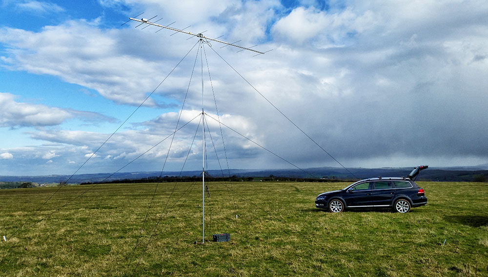
First trial erection went completely to plan, set up on my own.
The finished weight of the mast INCLUDING guy rings AND guy ropes is about 3.5kg. It’s actually currently weighing 3.7kg but that includes some aluminium blocks and plates, and stainless steel bolts, that are part of my yagi mount so not actually part of the mast. It doesn’t include the guy pegs and hammer of course. However for backpackers contests I can save nearly another 1kg by leaving the 30mm section behind and still achieve the 4m height limit. For the guy pegs I bought some 25x25x2mm aluminium extruded angle and cut them into 50cm stakes. The 4 stakes weight 387grams for all four including a bit of mud still on them.
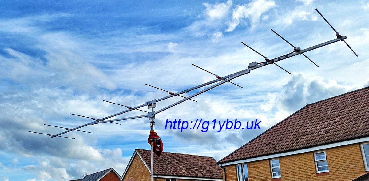
And with a 144MHz yagi:
In order to stop it spinning in the wind as I was using Armstrong Rotator method, I came up with a simple clamping system using some 3D printed half round pressure clamps and a bicycle quick release to lock/unlock it. Arm fixed in place to the ground with a simple guy peg:
As I use my new Yaesu FT-857D for portable operations including backpacking for things like SOTA activations I wanted a way to transport it securely to keep it from getting damaged. I have seen the select knob broken off on FT-857Ds so did not want that to happen. And keeping it from getting bashed and scratched would be nice whenever possible.
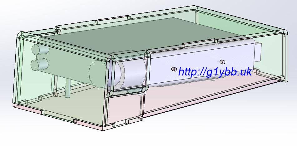
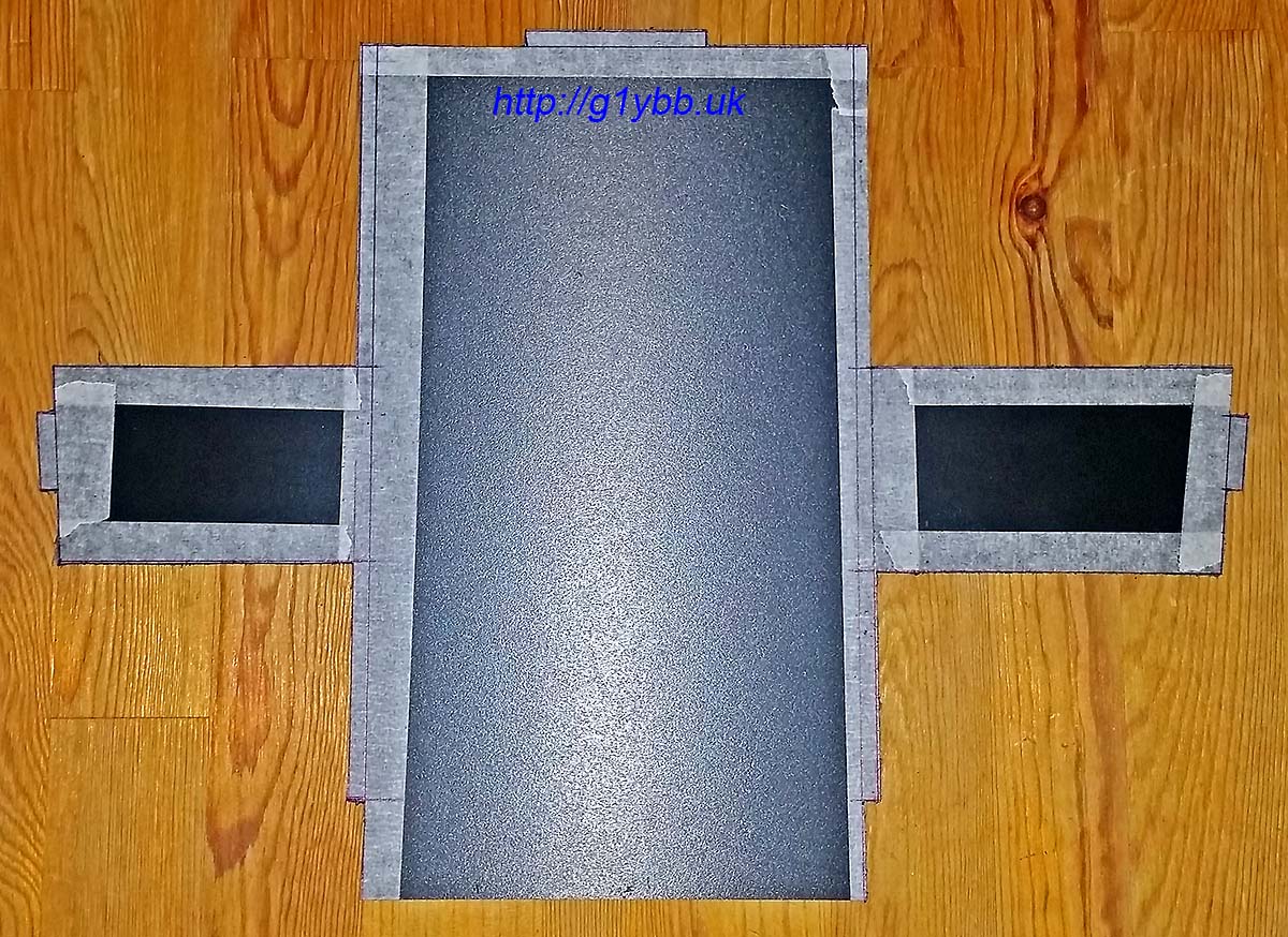
For my initial SOTA activations and portable operations I carried the FT-857D in a Lowepro camera rucksack inside my main backpacking rucksack. This kept it nice and safe but weighs over 1kg total and takes up a lot of space so I needed a better option. I didn’t like the look of any of the tube based manpack builds I saw on the internet a lot so I decided I needed to make something as I could not find a suitable lightweight container I could use. Talking with my friend he suggested some Foamex sheet that he uses as it is quite light and strong. This seemed like a plan so I drew up a two part cover using some 5mm Foamex which seemed strong enough to support the weight of the radio: The pink half will be fixed to the radio using the mobile mount screw holes and the green cover will slip on and be retained by a Velcro strap. The fixed base protection will allow it to be used on grass and stones without any damage or dirt ingress. The green cover protecting the knobs from damage in transit in the rucksack. The microphone will be retained in the space at the front, in a bublewrap bag. The 3D modelling predicted the total weight of the two parts of the protection to be about 500 grams.
I planned to use heat to form the shape of the parts, so marked out a sheet for cutting first using masking tape:
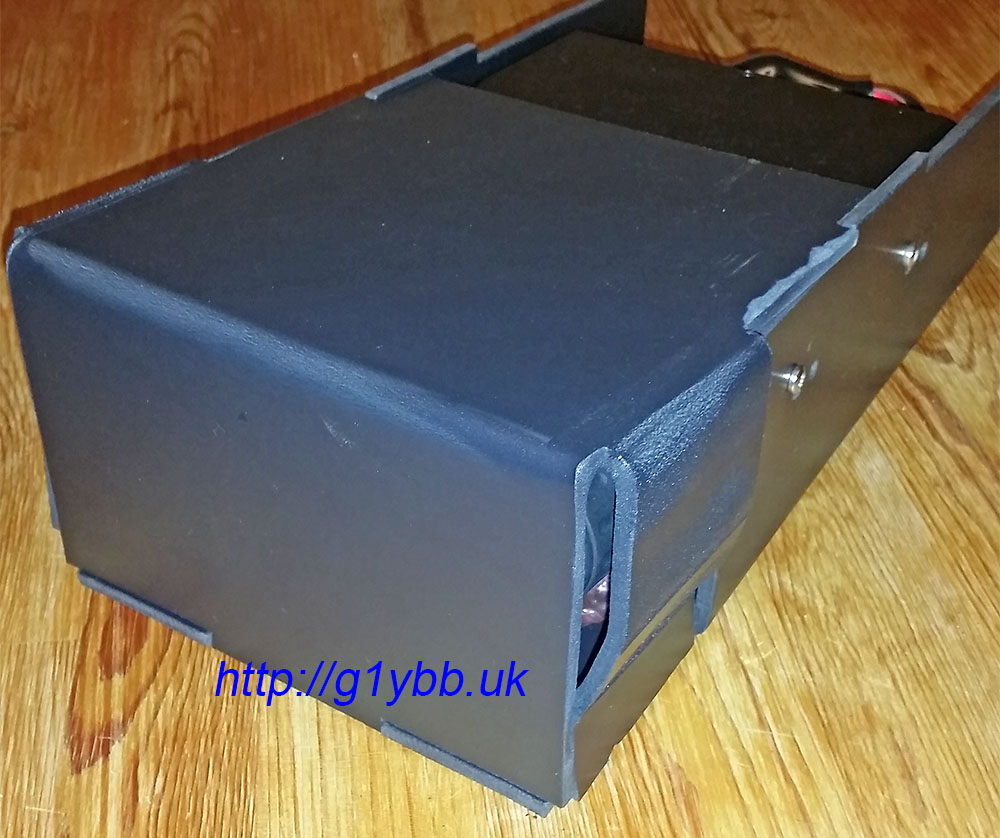
Next I took it up to my brother and got it cut out on a bandsaw then scraped all the sharp edges off with a steel ruler (my favourite deburring tool). Next job was to fold up the sides. My brother already made me a piece of MDF to match the width of the FT-857D to fold it around. I used a heat gun to soften the foamex and fold it up, holding in shape till cooled with a glass worktop saver:
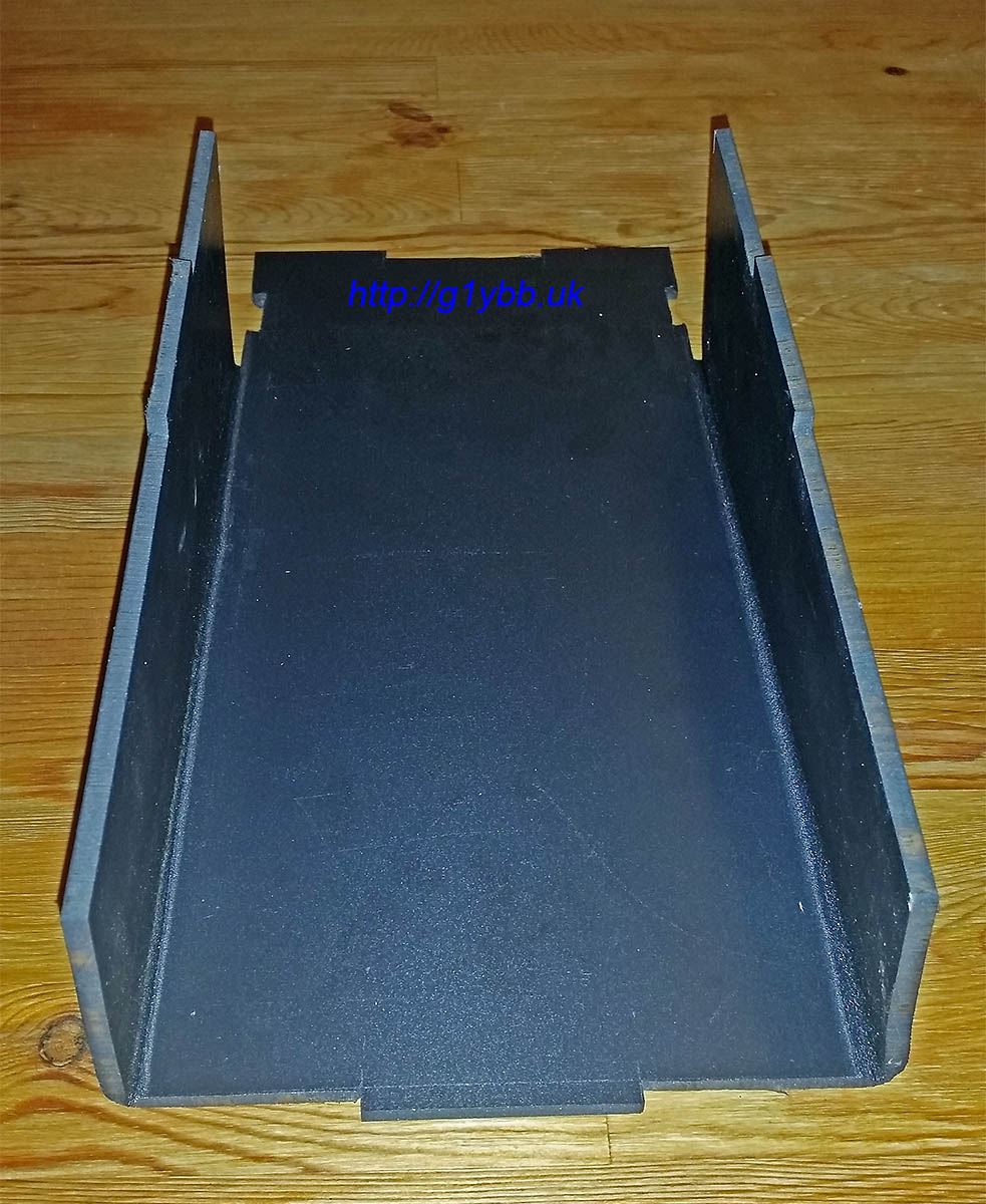
Both sides folded up:
Next drill some holes in the sides to mate with the mobile mount holes on the FT-857D. The rear extension will protect the DC input filter and the front will carry the microphone:
The sides are higher than the radio for the lid to clear the band Up Down buttons when fitted. Unfortunately the foamex panels I have available were not big enough for the lid as it has flaps on four sides making it take up more real estate. So I decided to make it in two halves and cement them together. The front half will be the more complicated one as it has to go around the tuning knob bulge so I started with that half:
The folding up of this part was more complex with staggered shapes but the length of the folds were shorter so at least it was a bit easier. It took a little reheating to get the shapes to sit exactly where they needed to be so the cosmetic appearance was not as good as I would like but mechanically the material still seemed structurally sound:
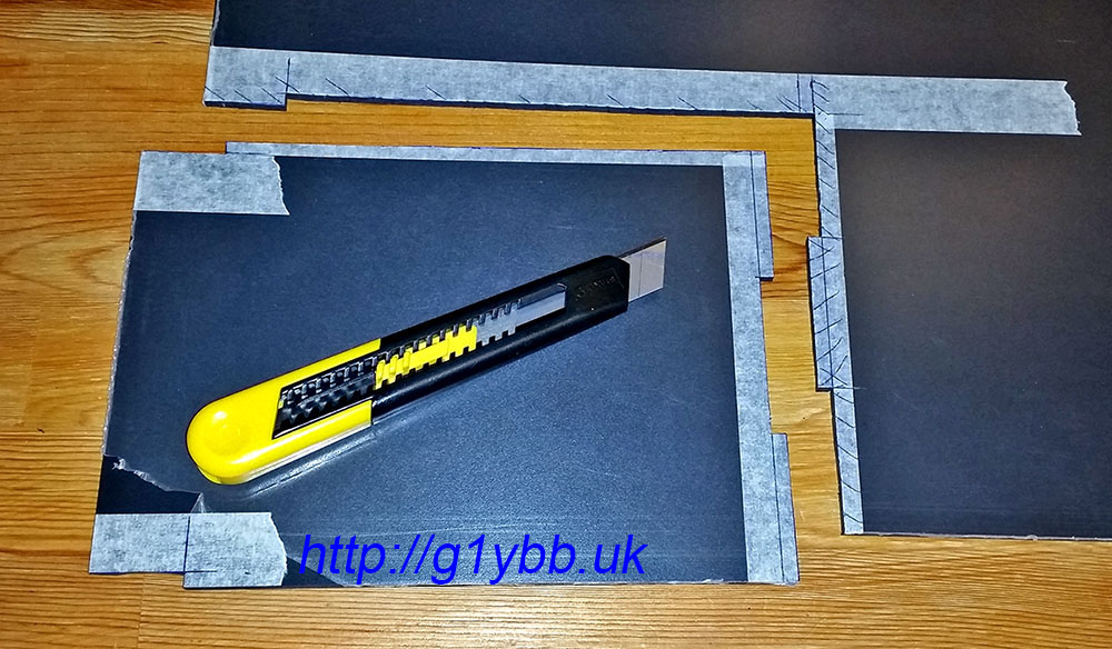
As the rear half of the cover was simpler I decided to cut it out with a knife rather than take it up to my brother to cut it with a band saw. It was straightforward enough just a bit heavy on one hand and shoulder:
And folded up and glued to the front half:
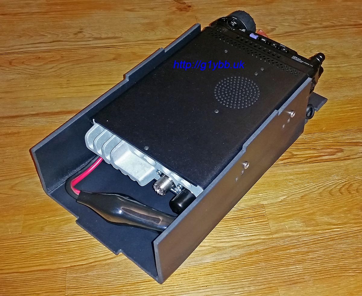
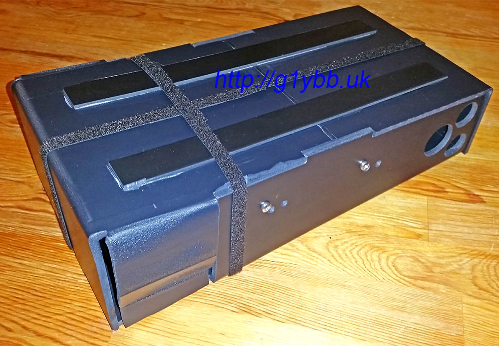
The join felt a little weak to be so I decided to glue some strips of thinner foamex along the top to strengthen it, and also make it a feature I could take advantage of. I could stand the base on the cover when operating to raise the operatin heaight and angle up and use the strengthen strips to locate the base so it didn’t slide or get knocked off. I added feet to the base to locate on the strips and finally drilled some airflow (and lightening) holes either side of the PA heat sink and along the base to recover some of the added weight from the strips. The video below shows the strips and feet in action. I decided to ditch the bubblewrap bag for the microphone and utilise the button for mic clips and drill a hole in the base for that to locate in and secure the mic in position with a small piece of foam. Finally two 10mm strips of Velcro keep the lid securely on and are located in small notches to stop the Velcro from moving in transit:
I’m looking forward to getting out and using this soon. The only cost to me was the Velcro from eBay and the glue, the foamex I am lucky that a friend had some to give me. I think the 540grams extra weight is worth the piece of mind knowing the radio should be safe and it takes up very little extra room than the radio itself and a lot less room than the current bag I have used to transport the radio. It’s not as cosmetically attractive as I would ideally like but this is the first time I have used this foamex and formed it with heat.
Finally here is a video showing how it looks in action and how it goes together for use and transport.
Edit: To assist others who may want to make their own version, I have added below the drawings I worked from to mark out and cut the two halves: Base Drawing Top Drawing