I have appeared in print a few times over the years mainly for winning the Practical Wireless magazine 144MHz QRP contest. That is I would mostly a national magazine although I know it certainly has some circulation into Europe.
Me as a ‘cover boy’ receiving a trophy for the 2016 PW 144MHz QRP contest:
But this year I have discovered that G1YBB is now published globally!
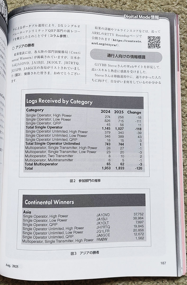
Following the drama I had getting RTTY mode to work ( https://g1ybb.uk/rtty-setup-on-ic7610-with-dxlog/ ) I have had some good results in world wide RTTY contests. In the CQ WPX RTTY contest I actually set a new single band QRL record which I was really pleased with ( results table ) and also more recently (results released wise) have set a DX (all the World outside of USA) all time record score for a QRP section. This got me (so far) a mention in the August 2025 QST magazine. The report is slightly wrong as I wasn’t using a vertical – I have emailed Jeff to clear that up – maybe I’ll get a mention again in the full article.
Link to the QST article: https://contests.arrl.org/ContestResults/2025/RTTY-RU-2025-FinalQSTResults.pdf
I hadn’t actually noticed this article was online, I found out when I received an email from Hisami 7L4IOU to say congratulations and that he had noticed the mention and looked at my website and thought my contesting information sign was good and could he mention it in the Japanese magazine CQ HamRadio. https://ham.cqpub.co.jp/
Obviously I said that would be great and we exchanged some more emails and then Hisami said he would send me a copy of the magazine. The last email was dated 6th July 2025.
Well, they certainly don’t mess about in Japan!
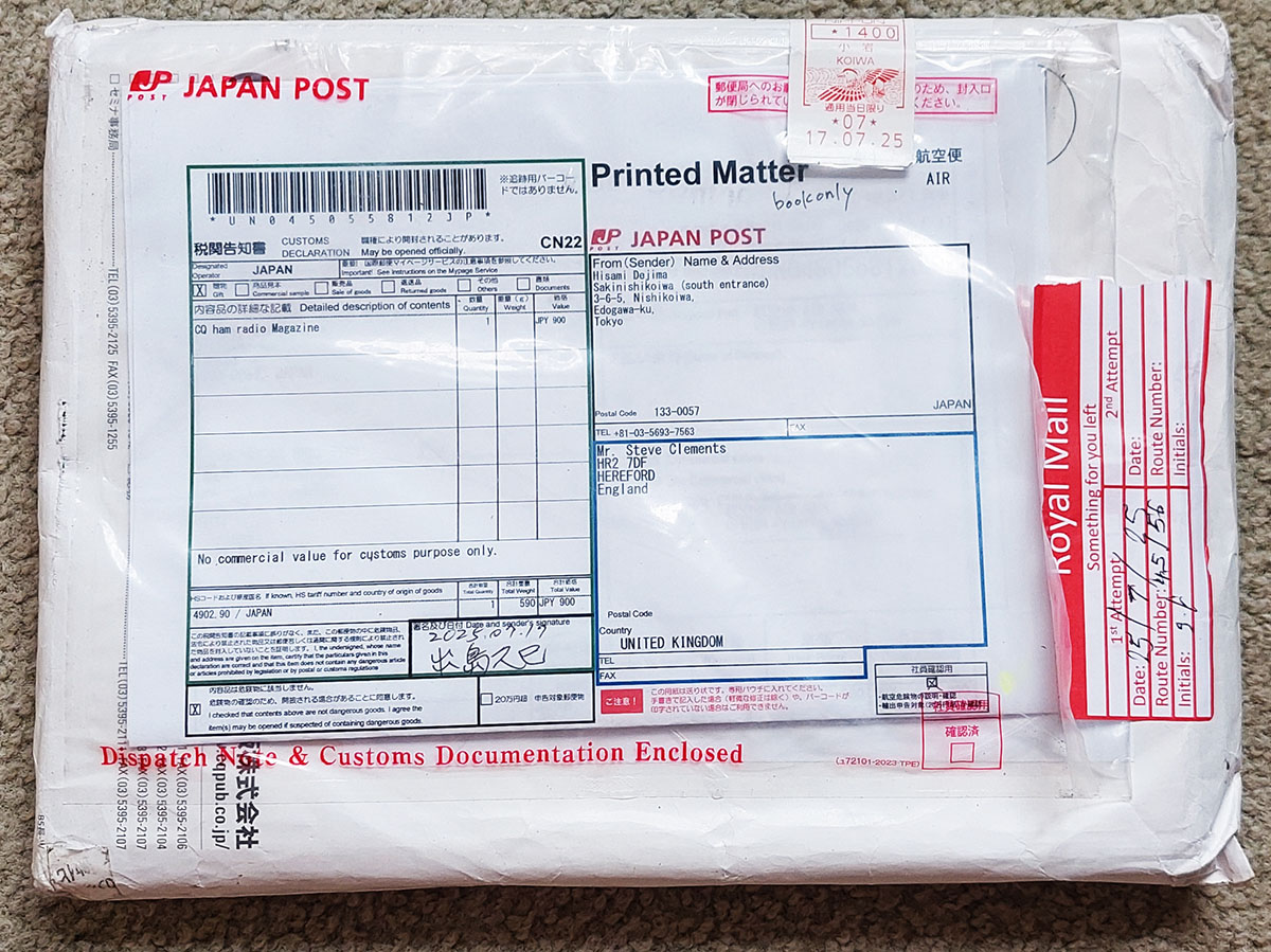
I didn’t know if Hisami meant a PDF copy by email or an actual paper copy. But I was only thinking towards the end of last week that if it IS a paper copy he never asked for my address. Then I though I wonder if he will use my (incomplete) address on QRZ as other countries may well not know it is an incomplete address. Before I had any time to think on this further my mum told me a book had come for me from Japan on Saturday 26th July 2025. You can see below the post mark date is 17th July! That 11 days from last email to hard copy in the post. And it’s THICK! And shipped to a partial address!
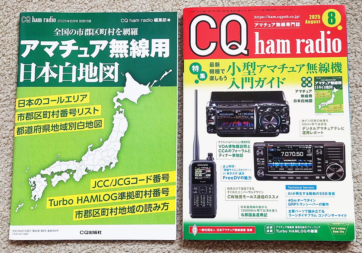
Opening the package revealed two books. One appeared to be a book of all the areas and regions in Japan and the other thicker one the main magazine.
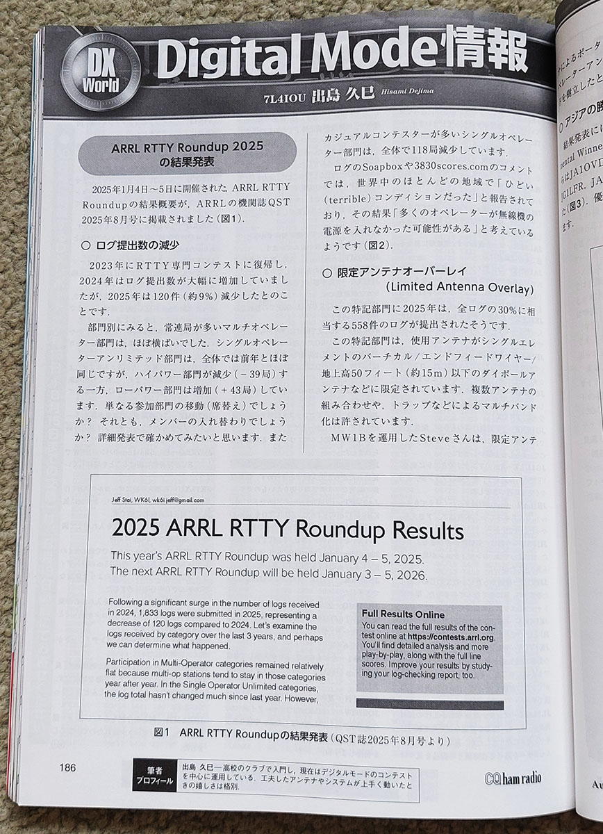
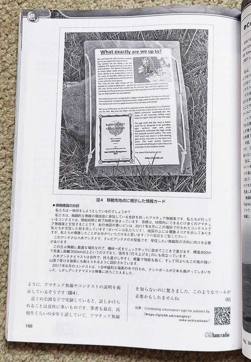
On opening it I found, not surprisingly, it’s almost 100% Japanese, with the odd sentence/phrase or two readable in English. A good excuse to flick through page by page and see what was in it. I eventually found the section where I thought I might get a mention starting at page 186. (handy the page numbers are readable).
Obviously I can’t read the article but it appears to be a report on the RTTY contet where I get mention with my short call MW1B and some talk about that and then some about the contesting sign and some other general stuff about me from my website. Cool.
It has to be said, Amateur Radio really does cross all boundaries and makes the World a smaller place! Wonder if I can get G1YBB now published globally in another corner of the World?
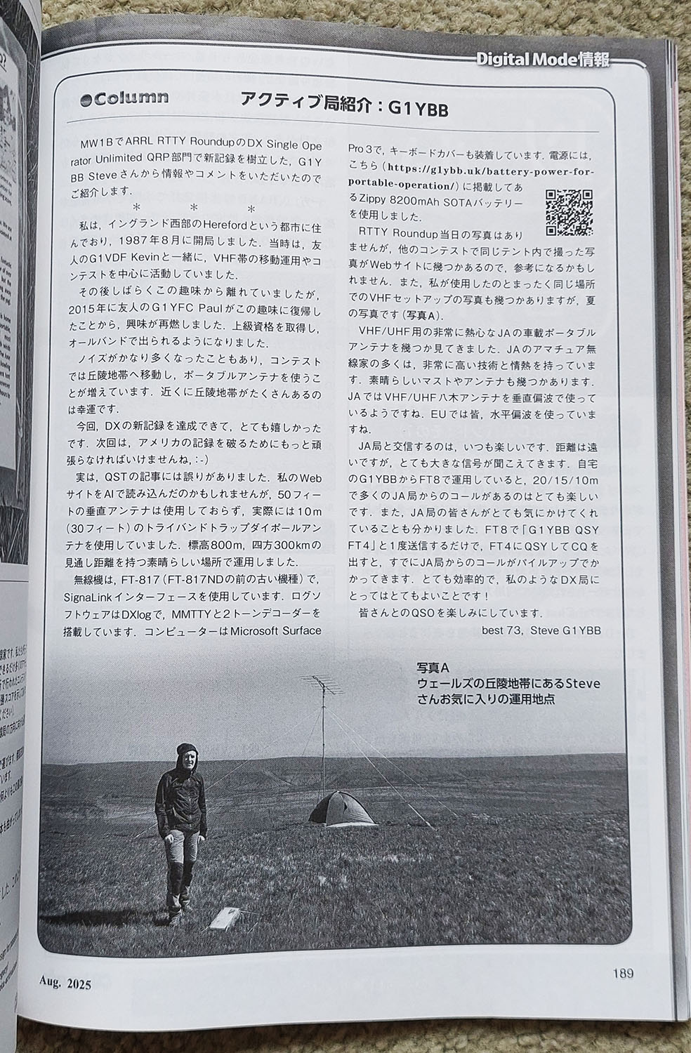
I’ve been making 3D printed parts for years now, all functional. Drill jigs, cutting jigs, antenna parts, all sorts. For most of these years I have only printed with PLA+ which is to be honest not the best choice, however it DOES work. You just need to know it’s limitations. The below antenna is one of 5 I made and every element mount, the dipole box and the N type box are all 3D printed in PLA+. I use this antenna portable (sometimes 2, I’ve yet to put any actual RF up 2 more and 5th one a friend uses) and it works great: However I have noticed some stress fractures in the tops of some of the element mounts. PLA+ is very rigid and a bit brittle. It also will distort in the heat of a parked car in the sun.
More recently I have got a new printer, the Bambu Lab P1S with AMS which I have actually experimented with and switched to using PETG, which I already knew is a stronger material.
Bearing in mind the above you may ask “Are 3D printed parts strong enough?”
Well this week I have come to the conclusion the answer is pretty much yes!
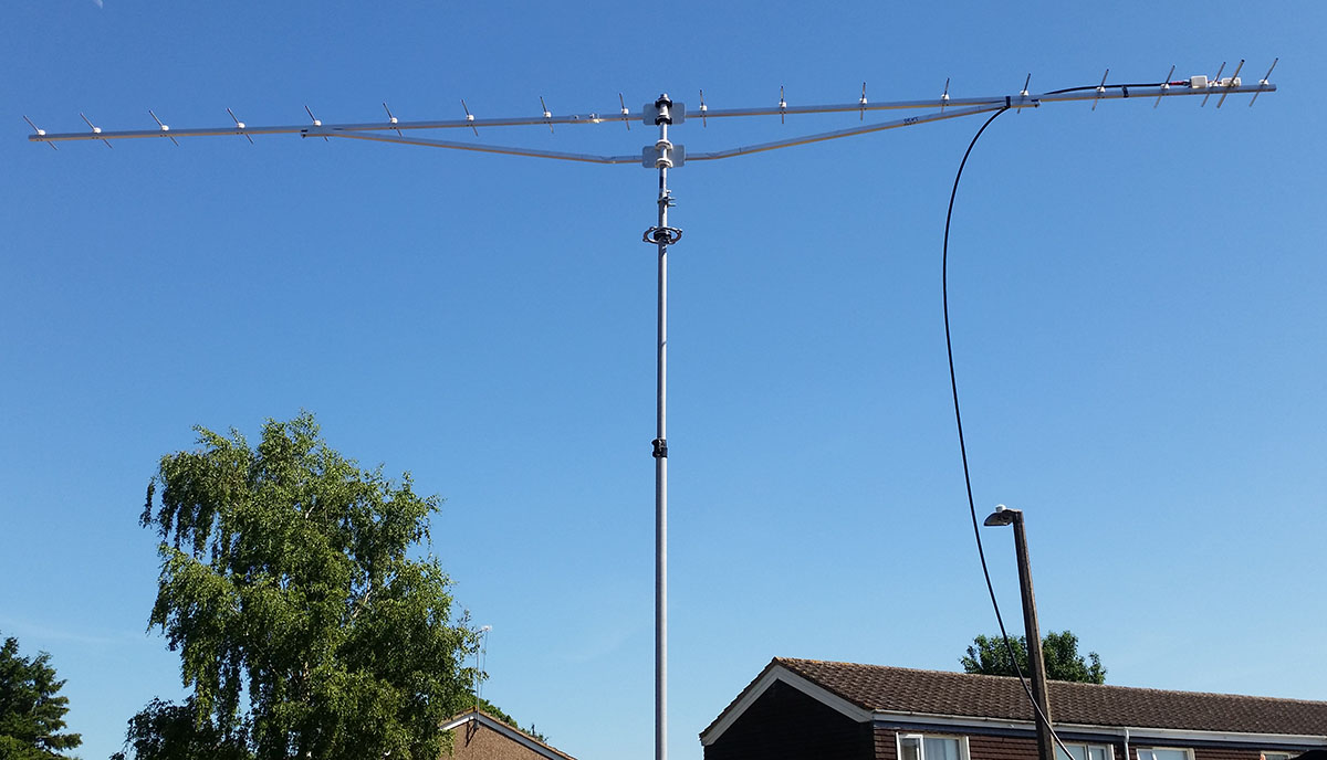
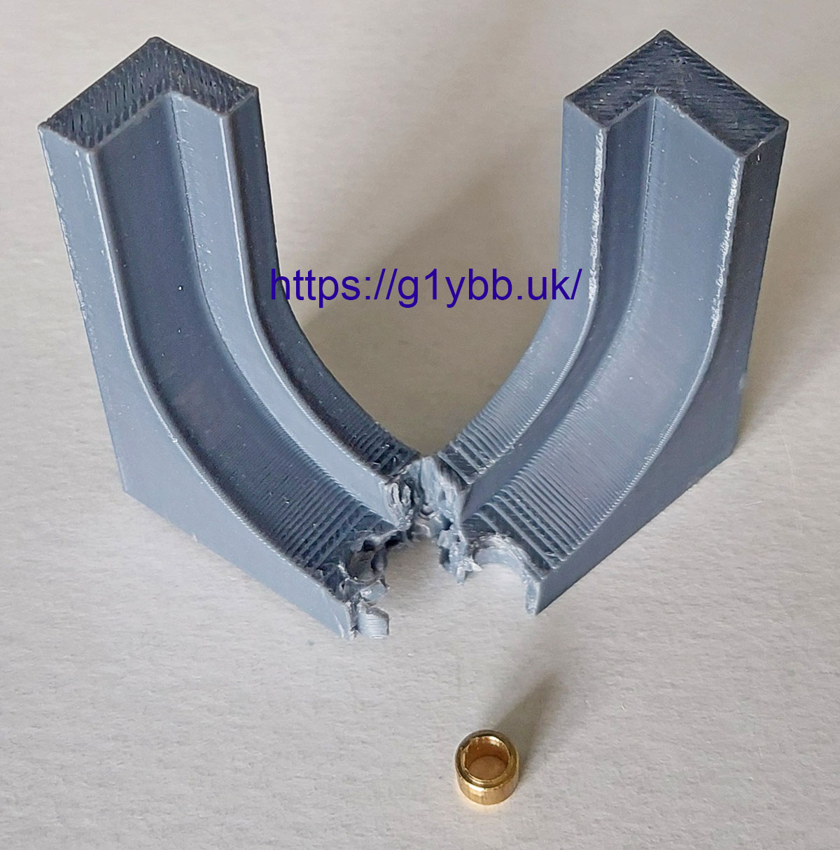
For one of my current antenna projects (will they ever end???) I have designed and printed some drilling jigs (nothing new there) but have decided as they will be used a few times I would turn some small brass bushes to press in so the drill doesn’t wear way any plastic and make the hole fit sloppy.
Here is one. You can see it is 60mm wide and the brass bush has a 6mm external diameter: I wasn’t happy with that jig so decided to tweak the design and print it again. But I didn’t want to turn another brass bush so needed to get it out. It’s pressed in and wasn’t keen on coming out at all.
No problem, I’ll just break the plastic at the ‘weak’ point where it is fitted and it will fall out.
Erm, nope. I tried by hand squeezing the legs together and trying to break it like a wishbone. All I got was sore dented hands. That PETG just refused to snap on me. I do print with decent wall counts but the fill on this wasn’t excessive as ‘only’ a drill jig.
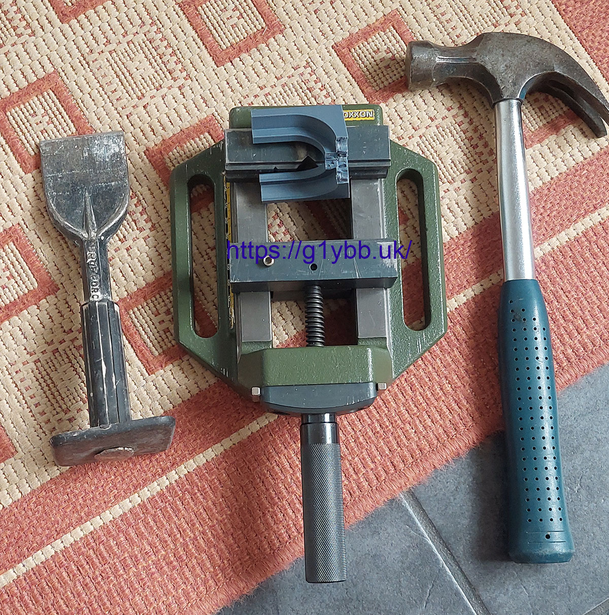
Time to resort to more forceful persuasion!
First I crushed the legs together in the drill press vice (because it’s more handy than my 6 inch vice) and I did break it at the middle point, but it still refused to let go of the brass bush.
So next I lay it across the jaws and split it sideways with a cold chisel (as that was close at hand too).
This did the job:
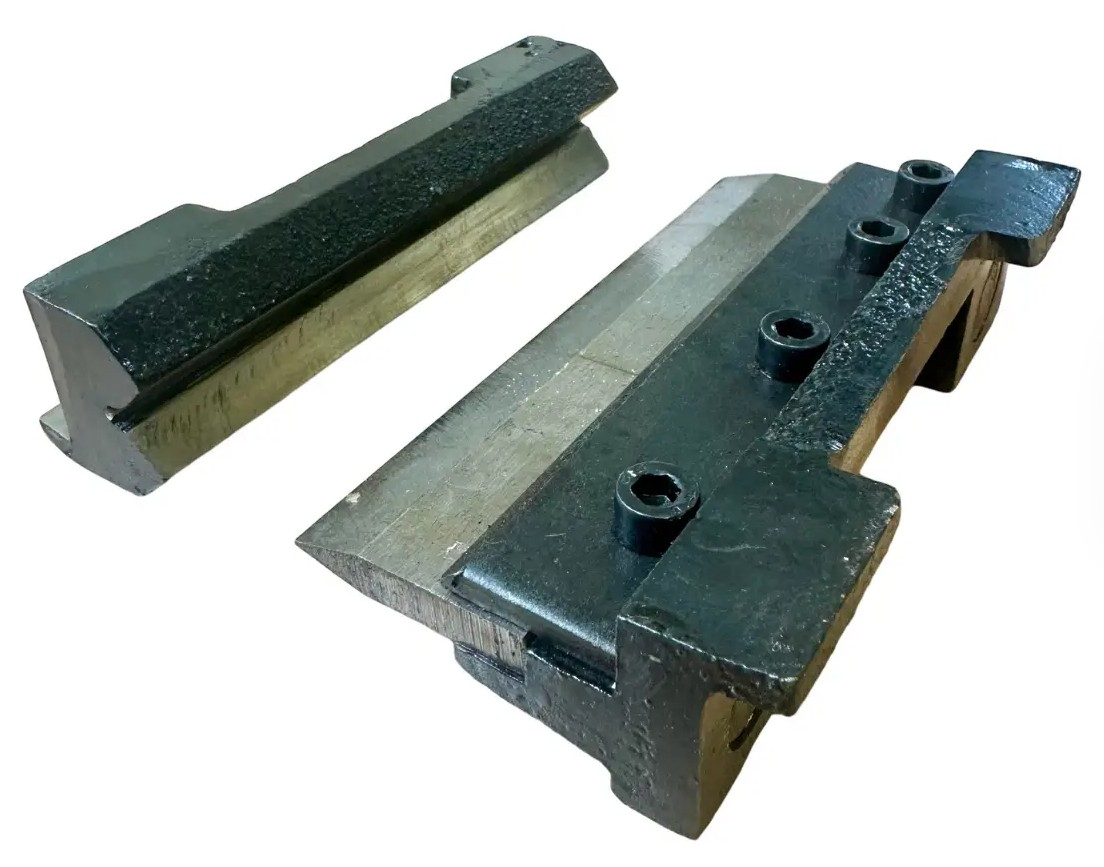
I must admit I was very pleasantly surprised at the length I had to go to in order to break this! When you look at the amount of material at the break below (that bush is 4mm tall) it’s really quite impressive.
So my conclusion is when asked “Are 3D printed parts strong enough?” is that yes they are if printed in the correct material and with an eye for manufacture at the design stage and with correct settings at the print stage.
PETG isn’t even the strongest material we can quite easily get and print with. But it is very readily available and as cheap as PLA/PLA+ pretty much. Some of the stronger materials like ASA need more consideration on fume handling etc so for now I am pretty pleased with the performance of PETG and only wish I had made the switch before!
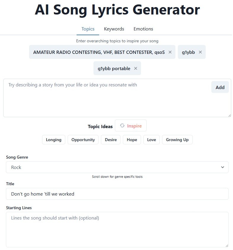
Just a bit of fun this time. When I am out portable contesting and chat to other contesters before the contest starts I always say to them “don’t go home ’till we worked” because sometimes you just forget to work some stations that are otherwise easy to work, especially if you are both busy during the contest. So it’s kind of my catchphrase amongst the UK VHF contesters.
I am not really a fan of a lot of AI, the AI generated results on web searches are often complete rubbish, but I have seen some quite good AI generated songs so I decided to try it out.
I used one website to generate the lyrics, with hardly any key phrases: I was quite impressed with the first go of the lyrics so went to another site to generate the song itself using the lyrics. Each time you generate the song you get a slightly different version. I did two and the first one I liked best!
I then decided to add it to some contesting photos to make a video as it’s often hard on social media to share just and audio track.
So here it is, I present to you for your amusement:
Don’t go home ’till we worked by G1YBB
At first glance my arbor press bending brake press modification might not seem amateur radio related but in fact the first job for it will be element mounting plate support brackets for a 10m moxon.
As a hobbyist we have probably all bent sheet metal in a vice tapping with bits of wood etc but it’s always a bit of a poor job at the end, certainly when I do it anyway! But some time ago I got hold of a small vice based bending set like this: At the time I didn’t actually have a vice only having a drill press vice but the jaws on that don’t open wide enough to take these so it sat around doing nothing for a while.
I did then decide I needed a vice for this and other jobs so got myself one and did some small brackets for my TMF-3 based DXcommander style vertical portable antenna. But in making these simple L shaped brackets I noticed a couple of things. It’s really hard to make a fold the exact angle you want at all and even harder to make more than one the same! Also, as my ‘workshop’ is usually the bench in the garden so my vice is packed away when not in use and not bolted down to a bench like most I have to clamp it down to stop all the weight at the front tipping it over. Additionally there is very little ‘throat’ so the longest flange you can make is about 3 inches, the distance above from the bending V to the top of the sliding body part. So I decided I would utilise my arbor press. continue reading
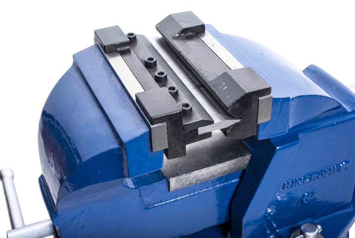
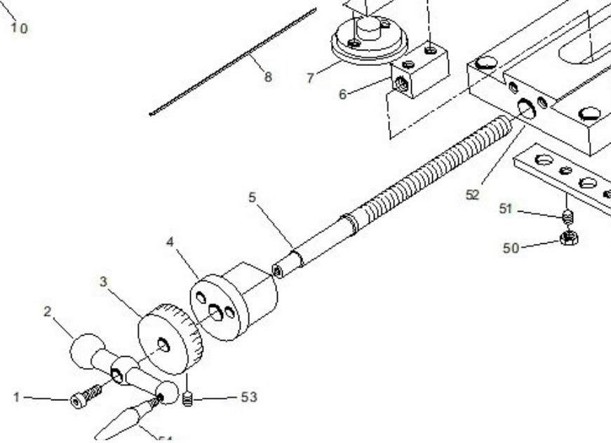
You may wonder what a mini lathe cross slide modification has to do with Amateur Radio but it is a tool I use a lot for radio gear. Mostly for the plastic bearing rings on my coax loop free guy rings ( https://g1ybb.uk/g1ybb-coax-loop-free-guy-rings/ ) but also for other little items like the YBB Washer ( https://g1ybb.uk/the-ybb-washer/ ) so very closely related to my radio activities.
My lathe is a cheap Warco mini lathe that I bought from an old friend G3LZM (now SK) and it sat unused for a LONG time. But now it sees more action and as a good friend of mine recently bought the Warco super mini lathe and has corrected some of the cost saving shortcuts I am trailing along adding a few to mine. So this one deals with the cross slide, or to be precise, the lead screw.
As seen in the exploded view above the lead screw (item 5) has a shoulder on it that sits in a machined recess in the cross slide boss (item 4) and it trapped up against the main body of the carriage (item 52). There is no bearing at all and the boss is aluminium. You can see this in my photo below: continue reading
I don’t actually collect QSL cards myself but I know people do so I do QSL via the bureau. The final courtesy etc so for many amateurs, QSL matters. NOT to Royal Mail it would appear.
Recently I had an email from my RSGB QSL sub manager telling me he was ending out my last two envelopes very soon. A couple of days later I received my ‘3 of 4’ envelope on its own. I assumed that ‘4 of 4’ hadn’t been sent but after waiting a couple more days I did check back with the sub manager and both were posted at the exact same time. Hmmm.
I’ve already previously had a completely empty torn bureau envelope delivered, thanks a bunch Royal Mail so I was expecting I’d never see that shipment of QSL cards and more amateurs around the world would think I was a git and not replying.
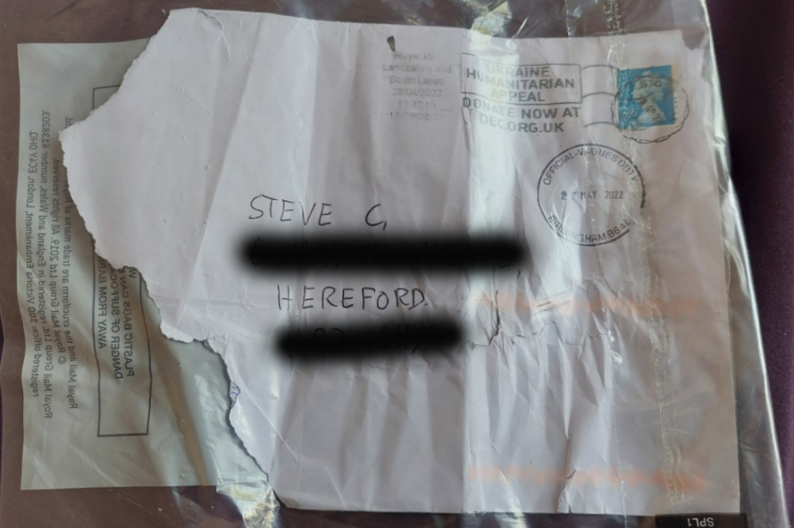
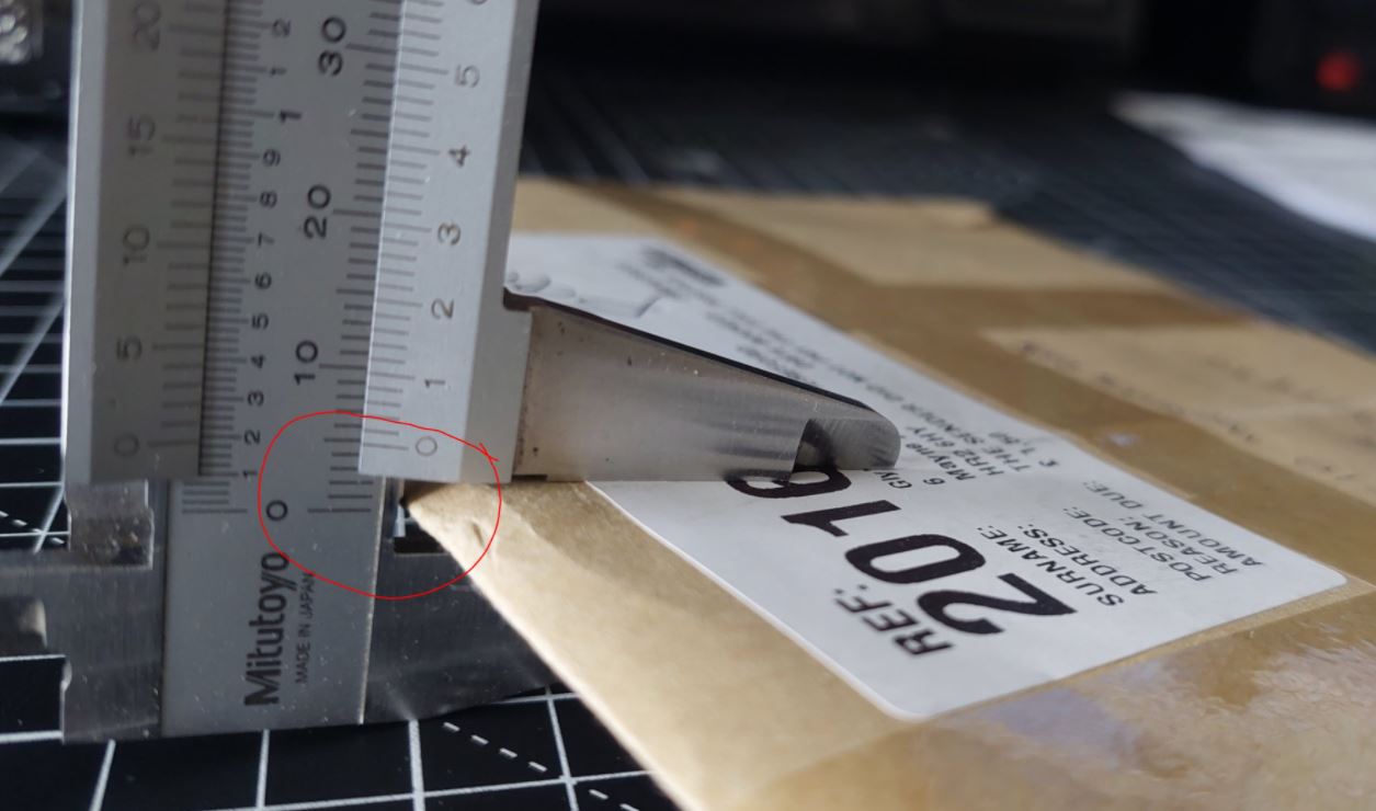
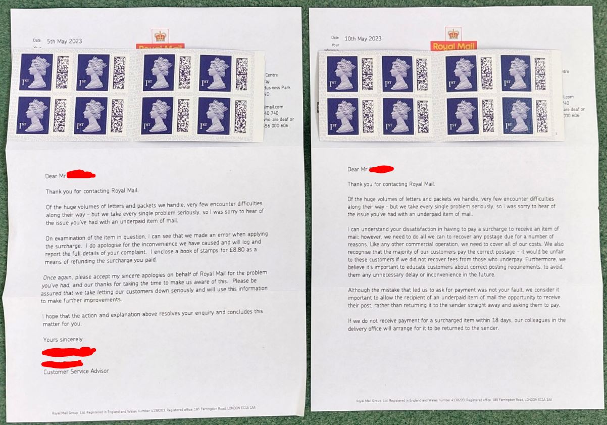
But a couple of weeks later through the door came saying “there is a fee to pay” of £1.50 for something giving the reason:
THE SENDER DID NOT PALL THE FULL POSTAGE
No clue to what it was but I had my suspicions. I paid the fee online then in a day or so sure enough through the door popped envelope ‘4 of 4’.
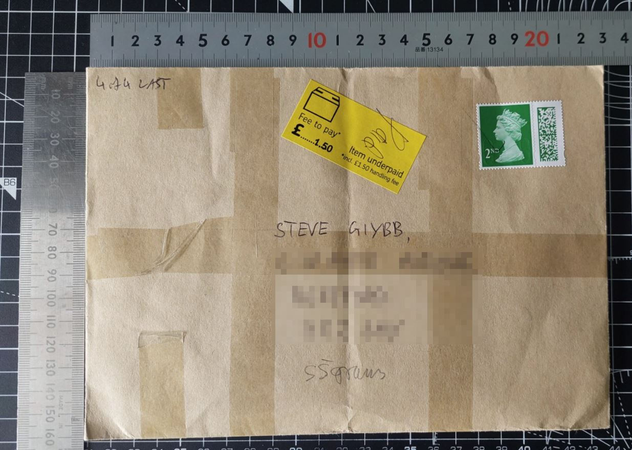
The very first thing I noticed was that the fee, supposedly for underpaid postage consisted of 100% handling fee.
So I got onto google to double check the sizes and weights for a normal letter which are:
And then double checked the letter even though I knew it would be fine. But I like to sure of my facts.
Clearly there is absolutely NOTHING wrong with this letter!
I decided I was going to take every step possible to recover what I consider extorted money. Might be only £1.50 but it might be £1.50 from 100s of 1000s of people, basically mass theft. I shared my annoyance on Facebook and was immediately directed to a group solely for people to advise each other on these matters so it is widespread.
Firstly I went down to my local sorting office wehre presumably my letter had lain for 2 weeks or so. They literally did not give a toss. Not the slightest. Just told me to pick up a card and ring that number.
Now we all know these customer service lines are deliberately undermanned in the hope that we will just give up. But I was on a mission now and sat at the computer working with the phone on speaker and let it work me down the enormous queue. Once through I did speak to a guy who said he would raise an issue but it didn’t sound very promising at all, I had the feeling I was being fobbed off.
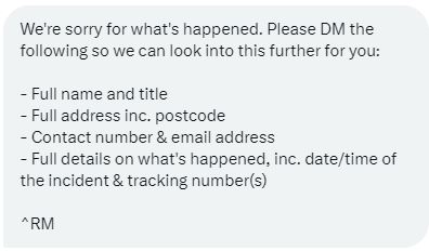
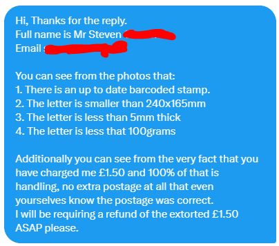
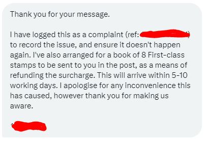
So I decided to speak up on Twitter. I find Twitter very good because all posts are public and you can tag them in a post which then appears on their feed and they can’t delete it and as a result most will direct message you to try to shut you up. Sure enough in a day or so I received the following DM: To which I replied with the 3 photographs above (unpixellated of course) and this accompanying text: Then 4 days later I got another reply: By this time I was about to leave for a 10 day holiday so I had to wait until my return to see if I would actually receive the promised book of stamps. I noticed two matching envelopes in the mail pile and was surprised to see this:
So I am guessing that both the phone call and the Twitter chat resulted in one of each letters. Clearly there is no coherency within the company as both were unaware of each other dealing with my complaints by the look of it.
So my moral of this long winded story is:
DON’T LET THEM GET AWAY WITH RIPPING YOU OFF.
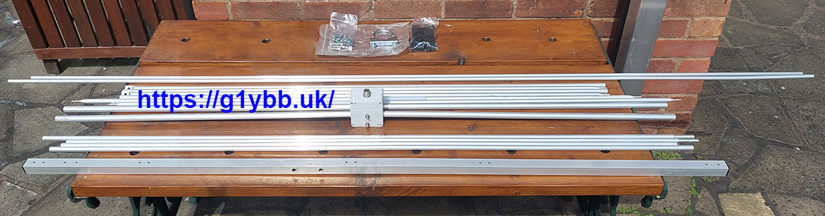
As an avid antenna constructor myself this is a bit of an unusual post for me. It comes around as I was planning to build myself a dual 10m and 6m beam based on the DK7ZB design on this page (link). I was already running late as the Es season was well underway and in chatting with the Hereford club members Clive G8LNR said there was a tri band version of the same thing doing nothing I could borrow. It was made by VPA Systems and sold by TelTad on this page (link). This was ideal for me as it would save quite a lot of time, so I leapt at the chance and fetched it to my house to build.
This is a lightweight budget end of the market antenna with a claimed weight of 3kg and costing 193€ but that is ideal for my purposes. I retract my mast to gutter height when not in use and I don’t want heavy antennas on the aluminium mast (I’d love the Optibeam OB6-3M but it’s just too heavy).
Unravelling the bundle gave me this set of parts: which includes a set of Stauff style element mounts, stainless fittings and a single U bolt for fixing boom to mast. continue reading
Some great mast guying tips……in my humble opinion of course!
I love guy ropes. All masts are just so much safer well guyed in my opinion.
I recently made my own 3 section aluminium winch up and luffing mast for the base station (must detail that one day!) that needed guys for my own peace of mind. So I wanted some good secure ways of keeping is safely guyed when up and retracted. So the below is what I came up with with some experience in other hobbies and some research. I’m really pleased with it so thought I would share.
Anchors.
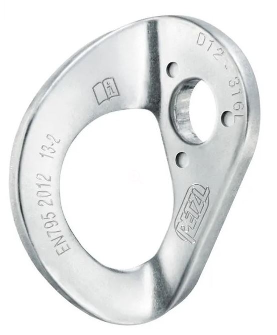
The garden is very small and fully paved but does have a 6 feet or so brick wall on two sides and a concrete post on the 3rd that I could use to guy to. So bolting a fixing to the wall was the obvious answer. I’d already bolted some eye rawl bolts in before but they were too small for the snap links I wanted to use and they didn’t fill me with 100% confidence. What came to mind as the perfect solution was bolt on hangers used in climbing walls for clipping the top ropes into. I could then bolt through the bricks and it would be bombproof. They look like this (though I would be using them upside down as our ropes go up not down!): I got stainless ones from Needlesports here (link) for under £3 each as they will be outside 24/7. continue reading
Welcome to your new callsign. Congratulations on getting your shiny new callsign! And welcome to the Amateur Radio hobby. You may be wondering what to do with it now you have it! The foundation training cannot cover even a small part of the many facets of the hobby so I thought I would share a few of my thoughts, experiences and some of the threads in radio that I am aware of. There are many more I don’t! This is a hobby where the World literally is your oyster.
The facets I mention below are no particular order other than they are the things I thought of.
Online Callsign Databases.
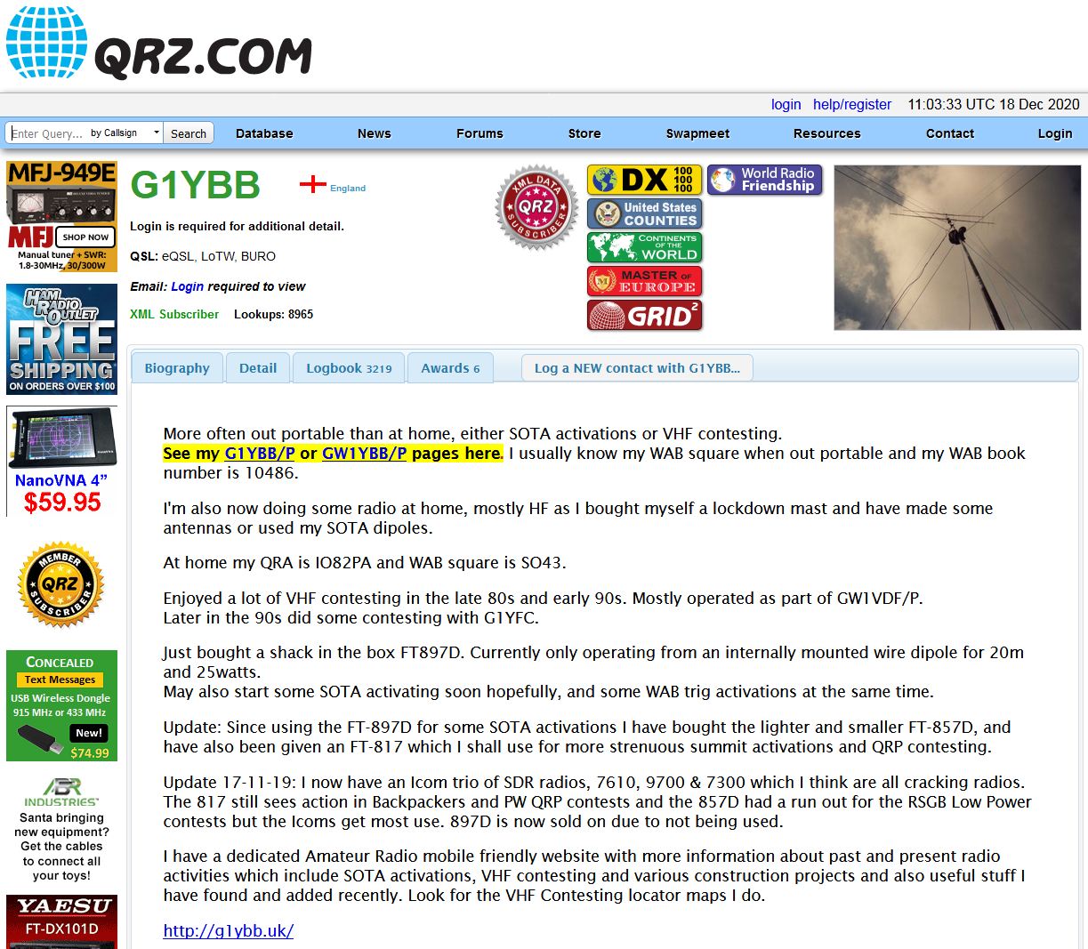
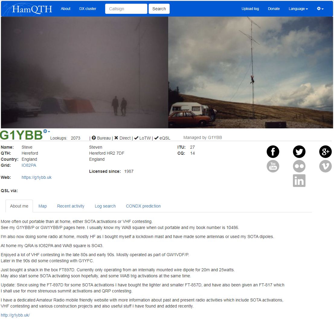
A great place to start is to get your new callsign registered on the online lookup sites. This is free and many people will look you up when they hear you on the radio, either manually or automatically with their logging software. The most used site is probably https://www.qrz.com but I would also recommend setting up accounts on https://www.hamqth.com and https://www.qrzcq.com as well. HamQTH and QRZCQ you just sign up with your callsign, on QRZ you need to make an account with your callsign as the user name and post to be added to the database forum Add My Call Sign to QRZ – Database Helpers Forum.
The following images are my entries on those three sites: Locator squares.
You will notice on the HamQTH and QRZCQ pages my locator IO82PA is stated. It’s very handy to know that and state it on your profiles. All or part of it is used in contests and data modes and grid square collection (more later on that).
To find it is really easy now with many web based help pages. I use this one: https://k7fry.com/grid/?qth=IO82PA&t=n
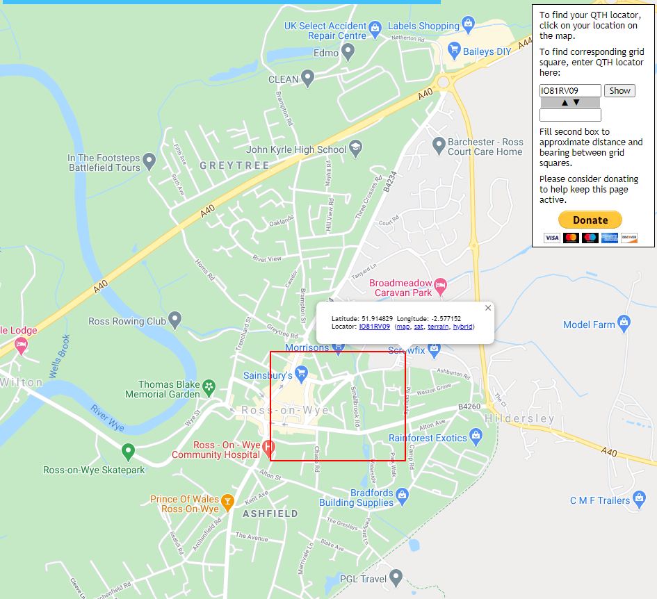
Clicking that link will take you to my locator square as an example, but you just need to zoom & drag the map to your house, click the map on it and then use the first 6 characters (as a rule 6 is plenty). For example if I lived in Ross-On-Wye and clicked my house there a box pops up containing my house and tells me the locator is IO81RV09 so I would use IO81RV:
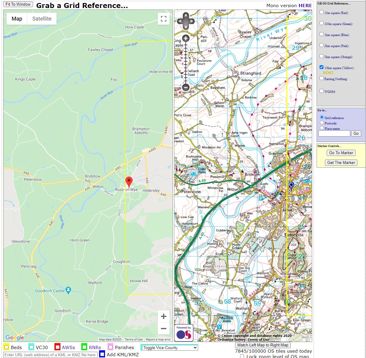
Another square worth knowing is your WAB (Worked All Britain) square as you may be asked this. This is just the 4 figure OS grid reference of your location. Again the internet makes this dead easy to find. On this site: https://www.bnhs.co.uk/2019/technology/grabagridref/gagr.php#map
I scroll the map again to my house in Ross-On-Wye, click the button “Get the mark” on the right hand side of the page and drag that to my house. Tick the “10km square (yellow)” tick box on the top right side of the page and your WAB square is shown, here it’s SO62: You are now pre-armed with information that sometimes catches out new hams that haven’t been told about it.
Logging.
I am a big fan of computer logging. It’s an easy and efficient way to log your QSOs. There are many advantages to this, many linked to some of the activities below. We hams like to spend all our money of radio stuff so some hams generously make free logging software available. I like and use one called Log4OM https://www.log4om.com/
This is very rich in features, too many to go into here, but I did write some pages on setting it up for portable operating, much of which is applicable to just setting up for your basic callsign: https://g1ybb.uk/portable-logging-with-log4om-and-online-log-sites/
Here is a screen grab of Log4OM. I have heard a station PE1EWR on air or he called me so I have put his callsign in the box. The software has looked him up on qrz.com and has filled in his name and locator for me and also pulled down the photograph he has on qrz.com. Also it is showing me where in the world he is and a closer zoomed in map of his location, based on his given 6 figure locator. You can see why your locator is an extremely useful piece of information. From that locator Log4OM is also telling me Frank is 434km from my house (really it’s centre to centre of our locator squares):
Log4OM can also upload your QSOs to the online logging sites automatically, even in real time as you log the QSOs, or at a later date from imports from other software like for example contest logging programs. Most of these are mentioned in my link above on Log4OM setup.
QSLs and eQSLs.
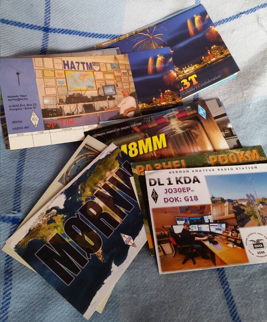
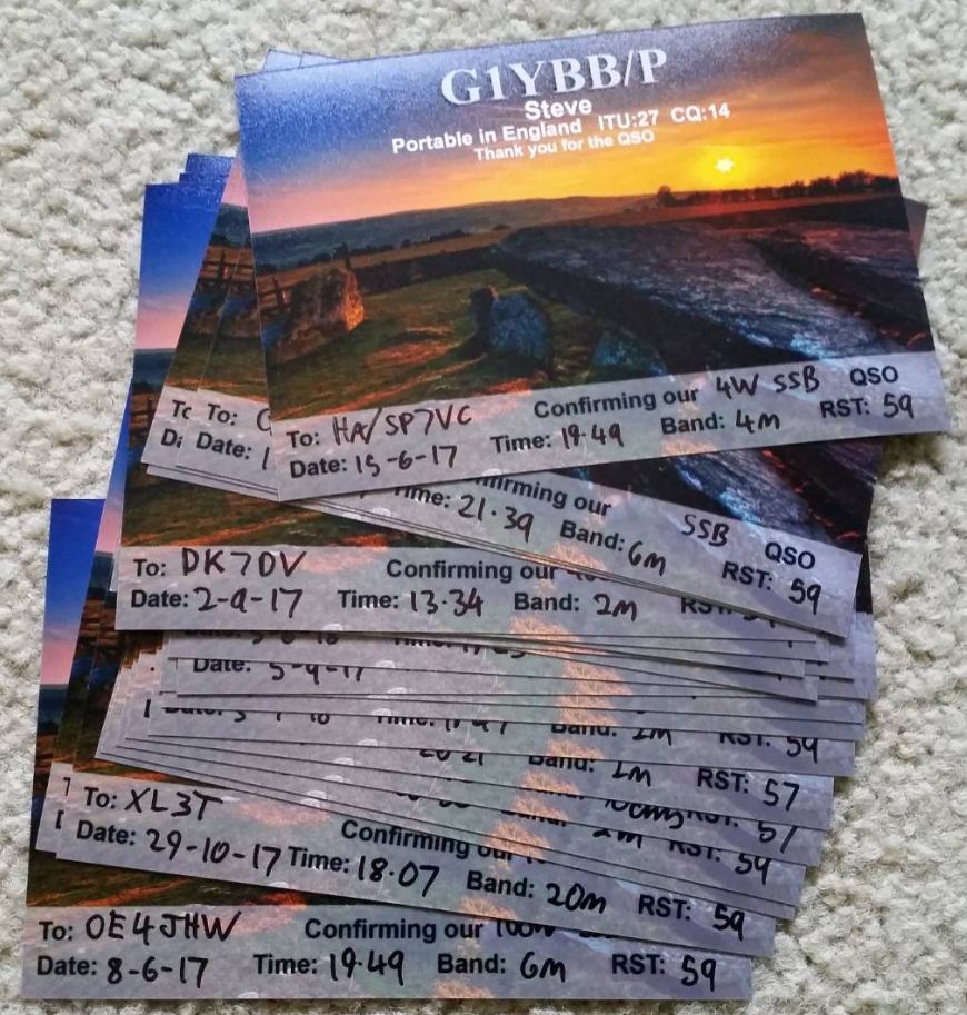
Not everyone’s cup of tea but many people like to exchange and collect QSL cards (confirmation of QSO) as the final act of completion of a QSO or to confirm a country or state for awards, or just because they like to do it. These historically are paper, like postcards but are also now widely done in digital form via the internet known as eQSLs.
As posting actual cards to many places would be expensive all the radio societies around the world run a service called the QSL Bureau. You can send QSL cards in bulk to you local bureau and they will distribute them around the world and the Bureau at the destination end will send them to individual hams. It is a very slow process but is a good option if QSL cards appeal to you. Personally I don’t collect them BUT as people do like to collect QSL cards if they send to me I will always reciprocate. Here is a batch of cards I received recently: And here is a batch of mine before going to the bureau:
For UK hams to make use of the bureau you need to be a member of the RSGB. The bureau information is here: https://rsgb.org/main/operating/qsl-bureau/
eQSLs are a much quicker process and can sometimes be exchanged literally within seconds of a QSO if both stations are logging online and uploading the QSOs in real time to the eQSL sites. Log4OM can do this. The main ones I use for eQSLs are eQSL https://www.eqsl.cc/qslcard/Index.cfm and HRDlog https://www.hrdlog.net/
A couple of sample EQSLs I have received:
Ok behind the sceens type of stuff out of the way, we need a radio!
Radios.
This has to be the most commonly asked question. What radio should I get that I can afford. Or another classic is “what is the best radio to get?”.
There is no answer to that question really without knowing a budget and interests. But you may not yet have found your radio interests so the answer is almost impossible to know.
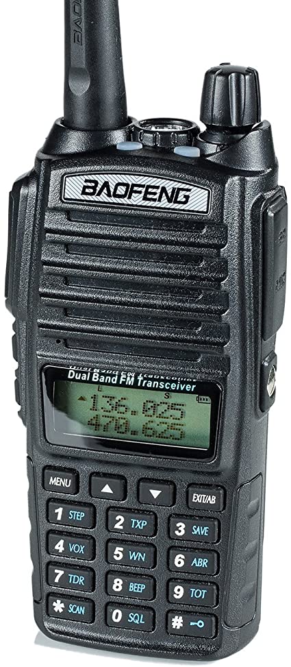
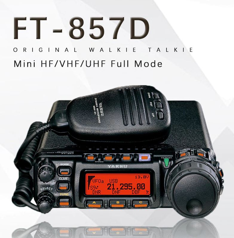
My advice is nearly always to buy a multimode radio if you can afford it. This means you can access FM for simplex and repeater QSOS like you would on the seemingly ubiquitous FM handheld but also opens up that world of other opportunities like SSB and CW, data modes, basically everything. For those who want an FM handheld I personally usually advise getting one of the really cheap Baofeng ones. The keyboard warriors will slate these but I have had no issues with mine and for only a few tenners you can be on 144/432MHz FM and save more tenners for a multimode! Multimode radio wise there is a vast assortment. For a first time radio I usually recommend a secondhand shack-in-a-box radio like a Yaesu FT857D or FT-897D. These have all the HF bands, 144MHz and 432MHz in one small unit and allow you to access all the most active bands and literally work the world on HF even with 10W on a foundation licence. Secondhand they will be in the reach of most budgets, probably starting around £350 and upwards. Whilst I now have dedicated HF radios and VHF/UHF/SHF radios I still love my FT-817 and FT-857D for certain portable operating where size is paramount. There are newer shack-in-a-box radios that have better interfacing to a computer such as the FT-991A.
Join your local club.
A great way to pick up tips, learn new things and even get on the air before you have your own radio gear is to join your local club. Admittedly as I type this in the middle of the Covid19 pandemic it’s not as easy as usual but many clubs are having meetings via Zoom etc. Many clubs have a club station that (in normal times) can be operated by members and meetings that ntroduce you to new things. There is a club finder tool on the RSGB website: https://rsgb.org/main/clubs/club-finder/
FM Repeaters.
These are very often most people’s first experience into amateur radio. Most areas have a local repeater in the vicinity that can be reached with a cheap hand held radio like the Baofeng. Repeater access is a little more involved than in ‘my day’ with a simple tone burst but the information is out there to get the job done.
The following links are a list of UK 144MHz and 432MHz repeaters, with details on how to set up your radio for access: https://ukrepeater.net/repeaterlist.htm?filter=2M https://ukrepeater.net/repeaterlist.htm?filter=70CM
You will often find most repeaters have someone who monitors it most of the time and is always willing to answer calls. As it’s FM and usually with squelch set you can have the radio monitoring in the background listening for people and respond to them. The range you can speak to people is the range of the repeater which is usually much further than you could do with a handheld on its own but limited to a local area, like Herfordshire for my local repeater for example.
SSB and CW.
These are mode often known as weak signal modes and where I like to do my operating. On HF you can speak literally all over the world and on VHF your range is vastly extended to 100s of km. 1000s with good conditions. This is usually because we use directional antennas to increase the range. This is a home made 9 element beam I made for 144MHz:
On HF though you can use bits of wire. This picture is an inverted V dipole made for 50MHz but I have made bigger versions for HF:
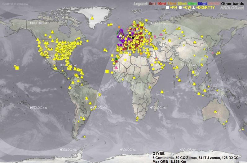
This is a map of QSOs I have made, mostly on SSB or a derived data mode, some CW on mostly bits of wire. The map itself was generated by HRDlog, one of the sites mentioned above and from logged QSOs uploaded with Log4OM:
Contesting.
Contests are organised events with a given start time and end time and the object is basically to contact as many other hams as possible in the time. This is probably how I spend most of my on air time. I like the competitive element and enjoy improving my skill to do better. As HF is world wide there is usually a contest to be heard most weekends. On VHF and up there are also many contests through the year.
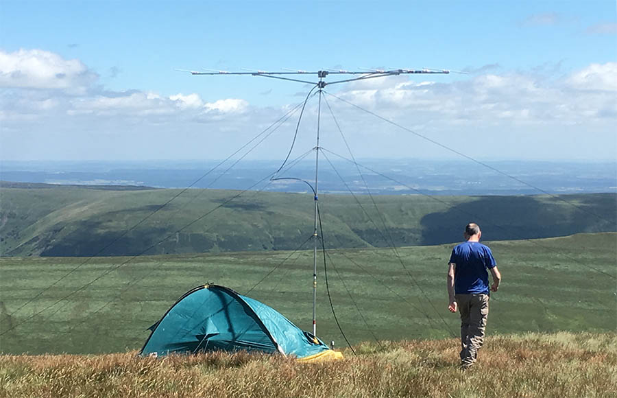
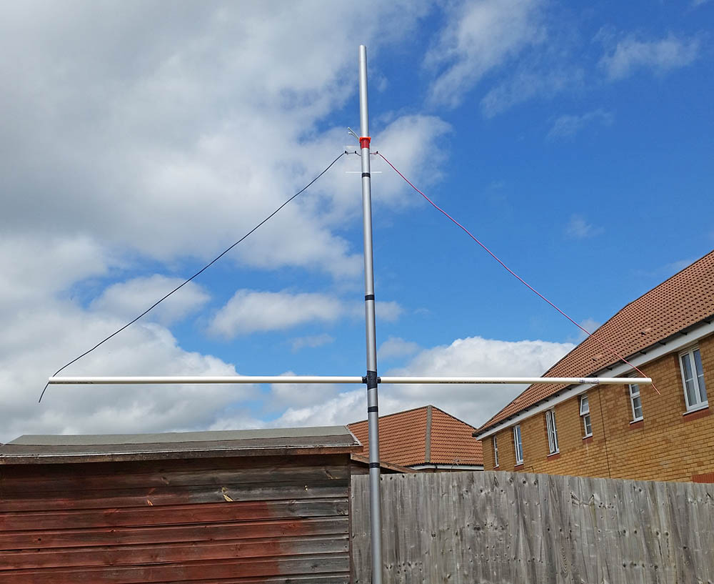
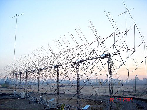
You don’t have to enter to take part, you can merely ‘give points away’ which is just answering the call of the stations who are hoping to win. Because contest stations want to do well they usually build high performing stations which means that a ‘normal’ station can be heard much further afield than normal so it can be a great way to make further QSOs. This is a common 144MHz style of contest setup: With a big antenna system and great spot at the other end, you can be heard a long way off.
The RSGB run a lot of contests each year, here are the VHF and HF calendars respectively: https://www.rsgbcc.org/cgi-bin/readcal.pl https://www.rsgbcc.org/hf/
For most of the VHF contests you only need to know that all important 6 figure locator like IO82PA and usually give the other station a signal report and serial number. The serial number is just the number of stations you have spoken to in that contest so far. If you get interested in this look up your local club in the results lists to see if they are active. They would be glad to have you aboard!
Signals from Space.
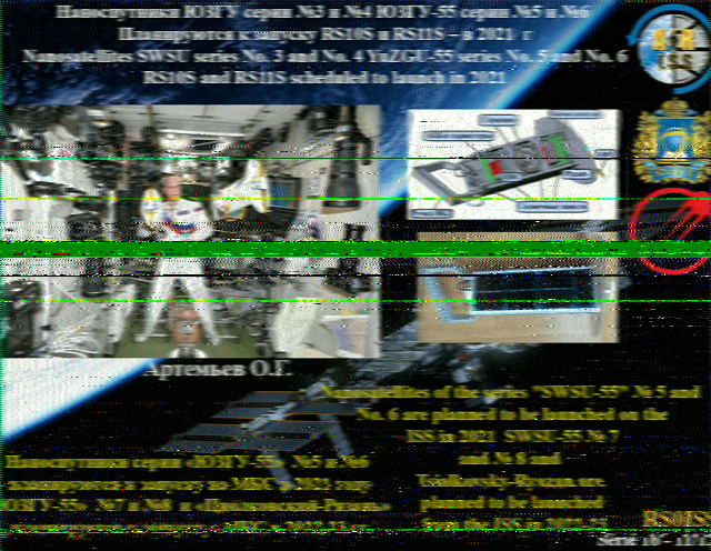
This is something I have only done recently and I think it’s really cool. The ISS (International Space Station) often transmits SSTV (slow scan TV) images as it passes overhead and these can be received with your little Baofeng 144MHz FM handheld in the garden and decoded with your smart phone running an app (I use Robot36 on my Android phone) held by the speaker of the Baofeng. These are a couple of pictures I decoded that way: I find this really cool.
Lots of useful information here: https://amsat-uk.org/beginners/iss-sstv/
Construction.
One of the great facets of this hobby for me is home construction. I prefer to let the Japanese make the radios, they are pretty good at it. But other things we can build ourselves. If I am not actually contesting, odds are I am building antennas for contesting. In the contest station above I built the tallest stack in the middle. A few of my projects are 9 element 2m yagi, 6m moxon, 20m moxon, 80m inverted V dipole, 20/30/40m link inverted V dipole.
There are many many plans for antennas on the web, literally any antenna you can think of.
This is a great low cost way to learn and experiment, and also get on more bands. Nothing beats the feeling of working new DX on an antenna you made!
SOTA and WAB.
SOTA (summits on the air) and WAB (Worked all Britain) are a couple of schemes that encourage people to be active on the bands. SOTA has activators and chasers. An activator takes his radio gear to a SOTA summit (hills and mountains) and makes QSOs with other people, chasers look for people on SOTA summits. Both can be rewarding and can introduce you to new places. Each activation gets you points and if you keep going can earn you an award. Info here: https://www.sota.org.uk/
WAB is similar but is based on collecting those WAB squares I mentioned earlier. Also trig points can be collected. More info here: http://wab.intermip.net/default.php
There are also other schemes like HEMA which are similar to SOTA. Loads to look out for!
Data Modes.
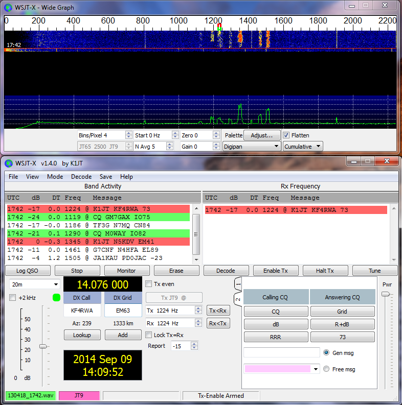
This is a hot newish mode devised for extra weak signal communication. It is done by connecting your computer to the radio and the computer sends tones to the computer which at the other end can be decoded at really low signal levels. On one hand it has led to lots of people sat on the data frequency instead of getting on the SSB or CW sections and working DX but on the other hand it is very family friendly as you are not shouting into a mic or tapping away on a CW key. Also the DX possibilities are excellent. The most often used program to do the data modes is WSJT-X found here: https://physics.princeton.edu/pulsar/k1jt/wsjtx.html
Looks complicated but once running it’s pretty easy to use. Plenty of how-tos on Youtube etc.
You can link it to your logging software to automatically log the QSOs. My setup is such that you make the QSO in WSJT-X. Once comepleted it prompts me to log it, which I do. It sends the QSO details straight to Lo4OM. Log4OM then (after a short delay to correct anything) automatically uploads the QSOs to the logging sites and often in a minute or so an email arrives to tell me the other station has confirmed! Awesome.
Here is an appalling quality video (two monitors wide compressed into small video size) of that happening in real time:
EME.
EME means Earth Moon Earth. basically you point your antenna at the moon, so does someone else and you use the moon as a reflector to bounce the signals to each other and get a QSO much further across the Earth than you could directly. Generally for this you need more power than the foundation licence so it is something that can make moving up through the licence levels worthwhile. It can be done with a good yagi for 144MHz (probably the busiest band maybe) and 100W if you have a big station the other end. The below image is an EME array built by RN6BN. Wow.
Chasing Awards.
Another thing people like to do is collect things that go towards awards. This can be DXCC (Countries) US States, Grid squares, IOTA (Islands On the Air) and so on. A benefit of the online logging sites and logging software as a lot of this can be done pretty much automatically. It relies on the other person confirming the QSO but other than that is pretty painless but can add an element of hunting for the next one.
For example, I just need Alaska to get my worked all States:
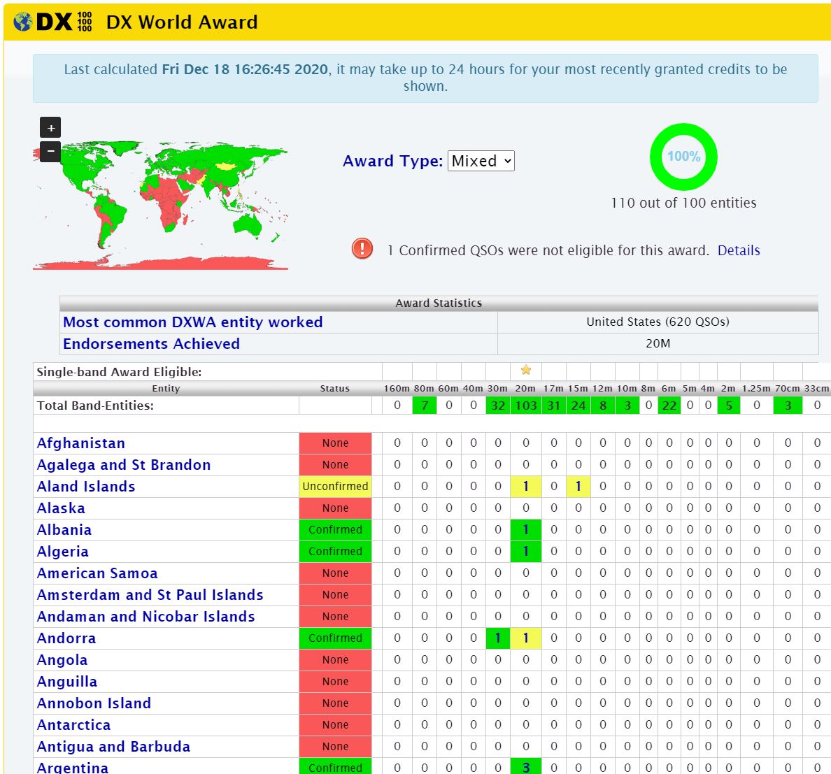
But I have managed to get my first 100 DXCC:
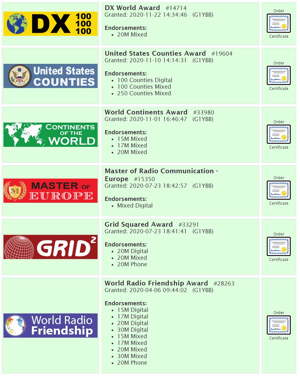
On my qrz.com profile awards tab you can see all the awards I have gathered just from having QSOs and uploading them all: As you can see from the images these are attainable on a per band basis so there is always a new challenge to chase!
These are just a few tasters to share some of the avenues of radio that a newly licenced ham could find interesting.
Also check out the RSGB Beyond Exams page for other practical progression via the RSGB.