This 4th session of the RSGB Backpackers series 2016 is the make or break session for us. Due to being away for the 5th and final session we go into this with 2 wins and a 2nd place. Rob G7LAS is hot on our heels with a win and two seconds. If we didn’t win this then Rob most likely would, and would also win the 5th session making 3 wins to two, an unassailable lead.
So the pressure was on!
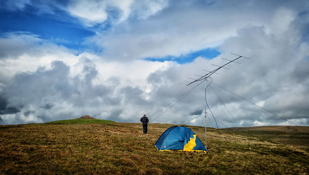
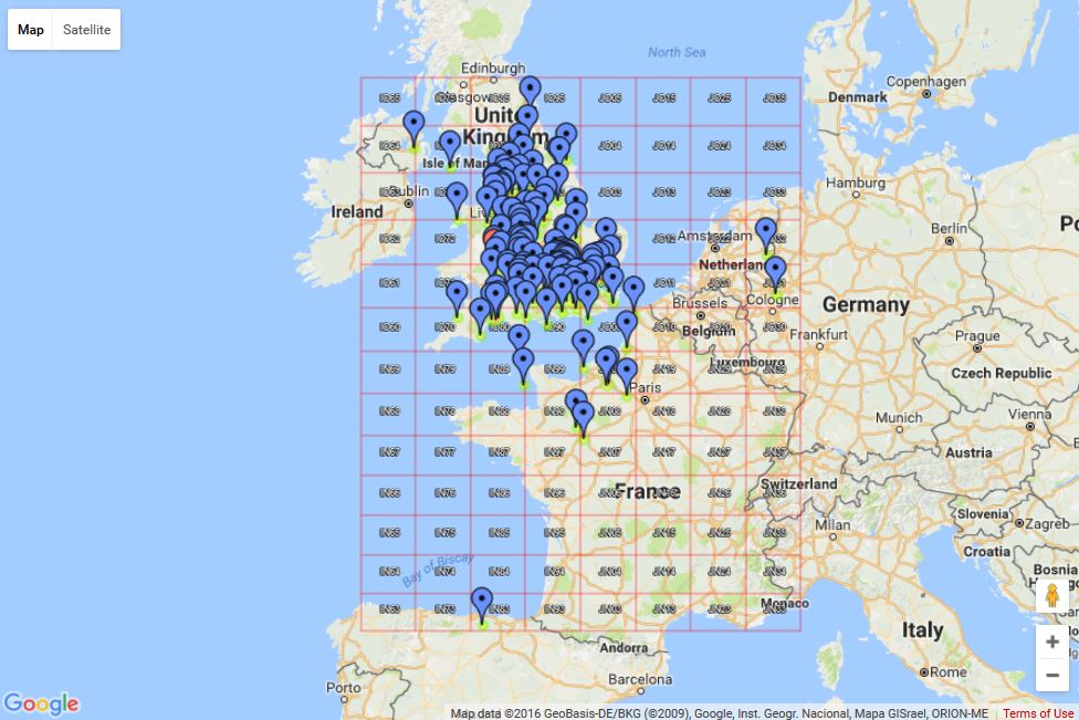
All we could do was continue with our busy work rate and rack up the QSOs as best we could whilst hopefully finding some good multipliers. The tropo forecast was for good conditions to the South and extended just up towards where our location in the Welsh Mountains is. Fingers crossed.
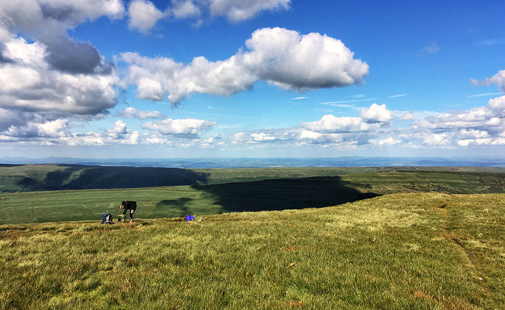
It was a glorious day when we arrived to set up, in fact when I got in the tent it was too hot, I had to take my top off and catch some breeze. Here is a 360°+ pano of our view (click here to view better):
This 4 hour contest starts 1 hour before both the RSGB Low Power and WAB QRP contests, which are 25W and 10W contests respectively. This meant we had a free band to get started on and didn’t expect to suffer too much QRM an hour in. This turned out to be the case and apart from local strong stations working a weaker running station 4KHz from us we had very little in the way of QRM.
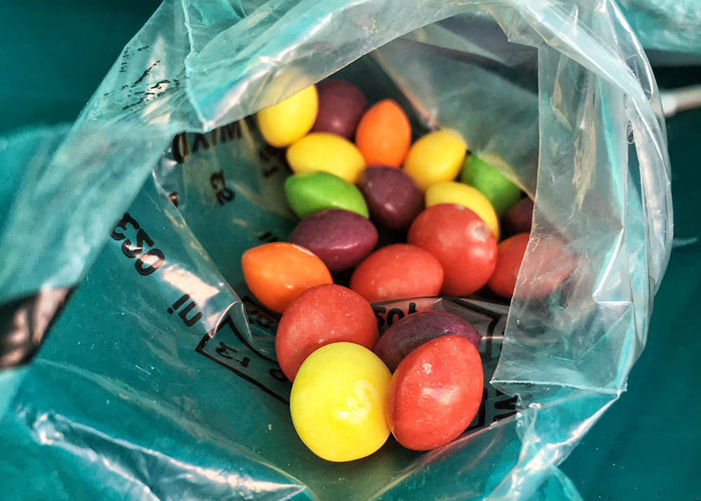
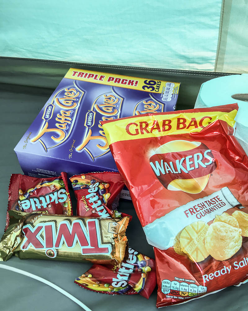
To keep us going we had the backpackers essential supplies:
Activity was good and so were conditions. The tropo forecast seemed to be on the ball and we worked several French stations, Germany, Netherlands and even Spain. Again no Belgium. One glaring omission for us was any Scottish stations, but we did get Guernsey, Jersey, Northern Ireland and Isle of Man.
By the time the contest was over it was so windy we were concerned about the antenna and mast even though it was engineered knowing the winds on the exposed point could be strong. The very second the time turned to red in Minos the radio was off and we were out taking down the antenna. That itself is interesting as one thing with telescopic masts is once you start to lower them your guys are no longer doing any good and the lightweight mast is at risk of bending. However we have developed a process for coping with this and soon had the antenna down. Here are some clips of the wind Paul took towards the end of and after the contest:
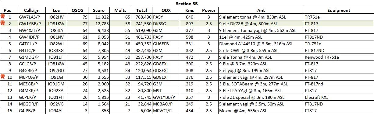
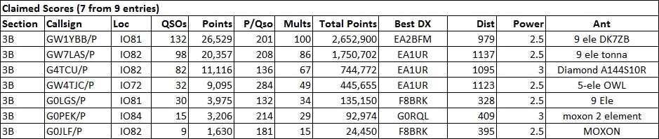
We did really well on both QSO count and multipliers and best DX a little under 1000km. Our score is I think the first score over the 2 million mark in the backpackers this century, certainly the 4th session.
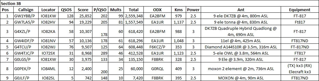
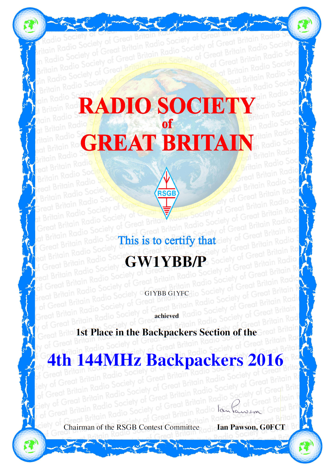
So, job done!! With 3000 normalised points from 3 sessions we have an unbeatable score! Woohoo! Rob G7LAS (as GW7LAS/P) kept us well on our toes but we managed to do the job. I can’t help notice that Rob and us having a good tussle at the top were the only entrants lugging our gear up to 800metres ASL for a great VHF take off. Good to see an even bigger tussle going on in the 10W section.
For this next instalment of the UKAC we have gone all posh. We are basically using the equipment we use in the Backpackers series with the slight exception we can use the full 5W power available from the FT-817. We are allowed to use 10W in the AL section and I think next session we are going to dig out the old Yaesu FT-225RD I have and used to use in the ‘old days’ to make use of that as we are finding 5W a struggle in these busier events. I have a month to make some mods to the 225RD to allow it to be used with my CQ caller mic which will save me also digging out the old (and large!) volatile RAM based CQ caller I still have that we used to use.
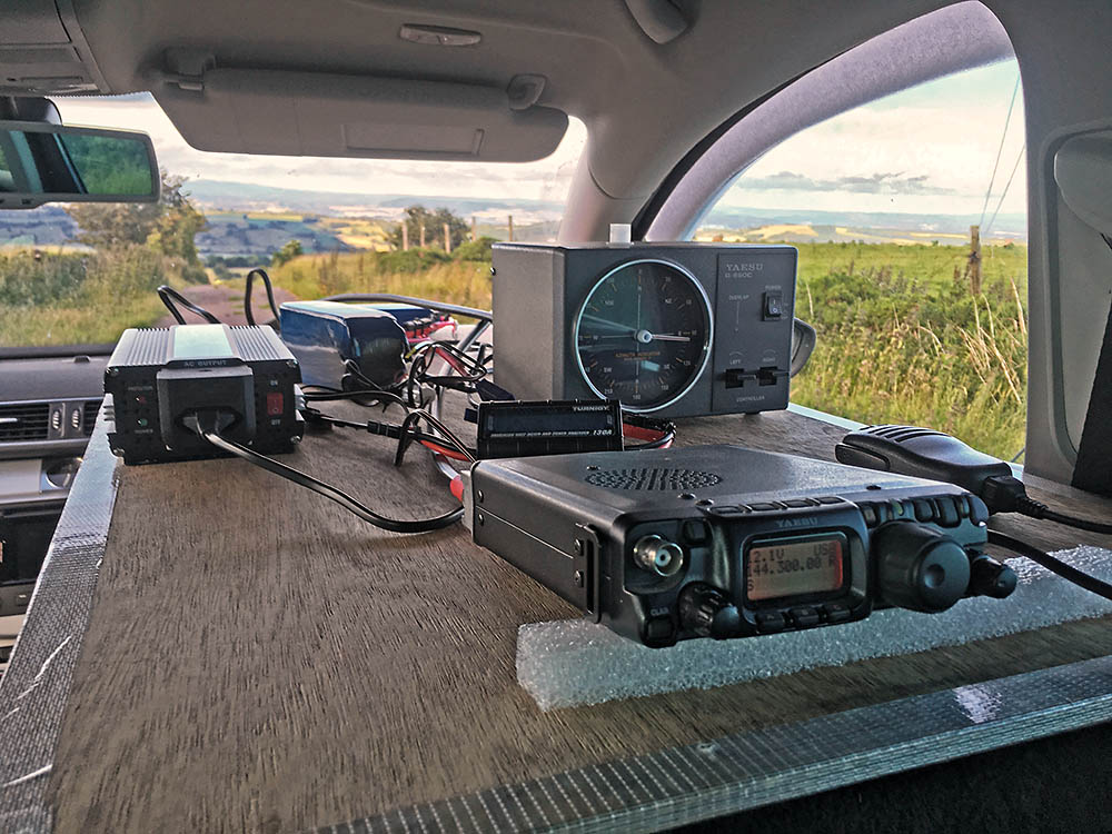
But the Armstrong rotator and lock system I have for the lightweight mast is designed to be used at ground level in a tent not sat in a car. Additionally with electric windows all round turning the beam is a bit of a pain with the ignition of car kept off. So I have bought a new Yaesu G-650C rotator to use. Whilst I do have 2 petrol generators I have only started one in recent times and that doesn’t run properly and needs a service. So I have bought a 150W 12V to 240V inverter and am running that off a small LiFePo4 battery. In use the rotator uses about 5A on the battery and about just under 1A when idle so I am turning the inverter off between rotations (when I remember anyway!).
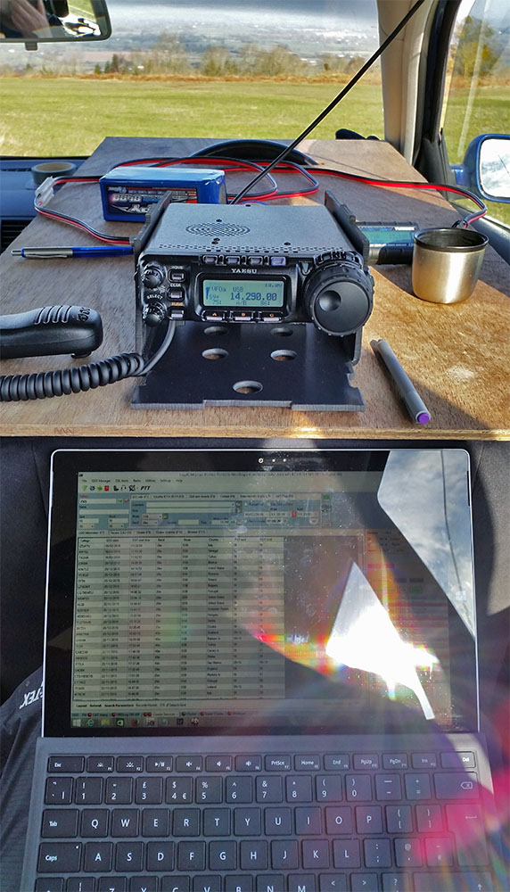
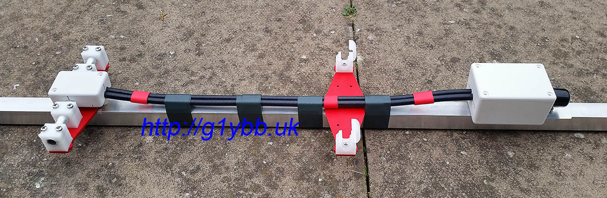
Here is the set up, one battery for the FT-817 and one for the rotator:
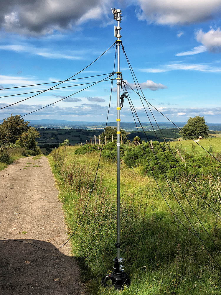
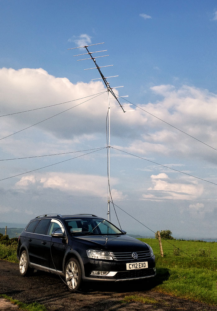
Outside the rotator is sitting on the ground rotating the whole mast which saves having a stub mast and hoisting up a relatively heavy lump of rotator atop the mast. The currently in use lightweight mast is too thin for the rotator to be used on it higher up anyway. The 3 sets of guys on the mast are very low friction by design and the whole thing weighs less than 10kg so nothing for the rotator to deal with. Titterstone Clee Hill can be seen at the end of the road:
It’s all about evolving the station and future improvements will see a drive on base and the use of a single ali scaffold pole for the mast rather than the lightweight telescopic one. This is mostly to speed up assembly and take down.
Once all set up we seemed to have great North South signals but really deep QSB. Once under way we found the band very busy and also had other stations calling CQ contest on the frequency we’d been on for over an hour. Quite irritating and didn’t help our QSO rate as we couldn’t be sure if stations calling in were calling us or someone else.
Paul G1YFC took a short video of me working Phil M0NVS/P:
QSO wise we did well on squares North but I don’t know what we have done to upset PA and ON as we haven’t worked one for a few contests in a row now. Not a single European station worked this time!
This 3rd session of the Backpackers series is timed to coincide with the last 3 hours of VHF NFD which meant finding a quiet frequency was going to be interesting.
On the up side it was a glorious day when we arrived at the summit site to set up:
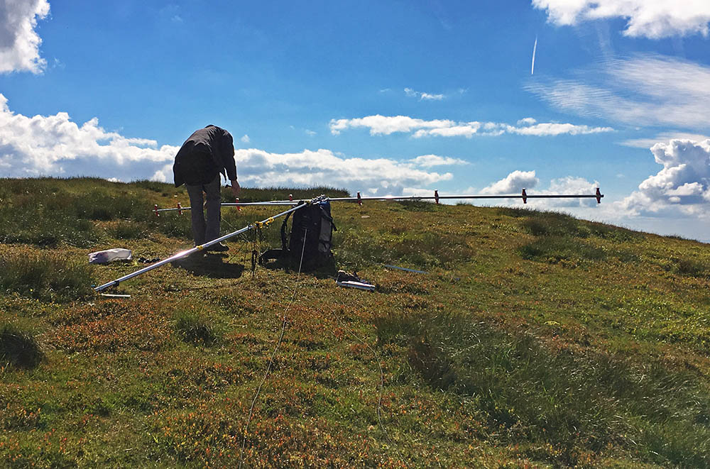
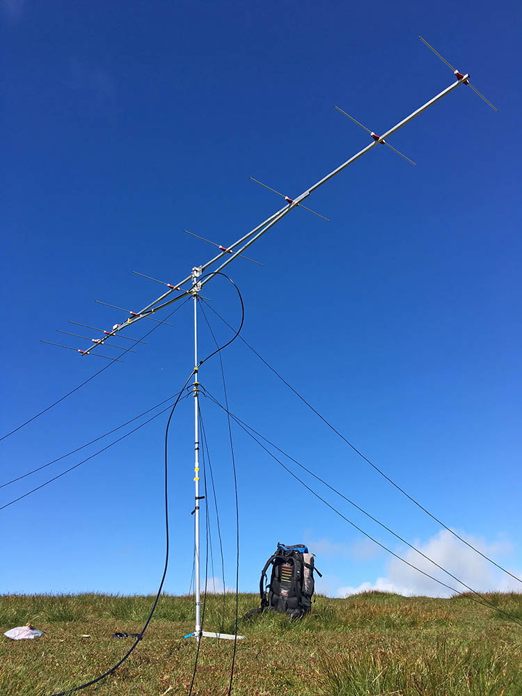
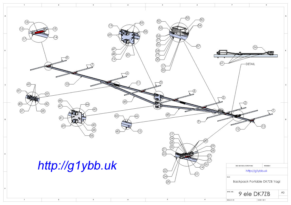
Building the 9 element portable DK7ZB yagi:
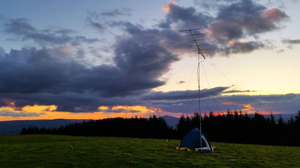
Antenna up and ready. Some strange coloured background behind it!
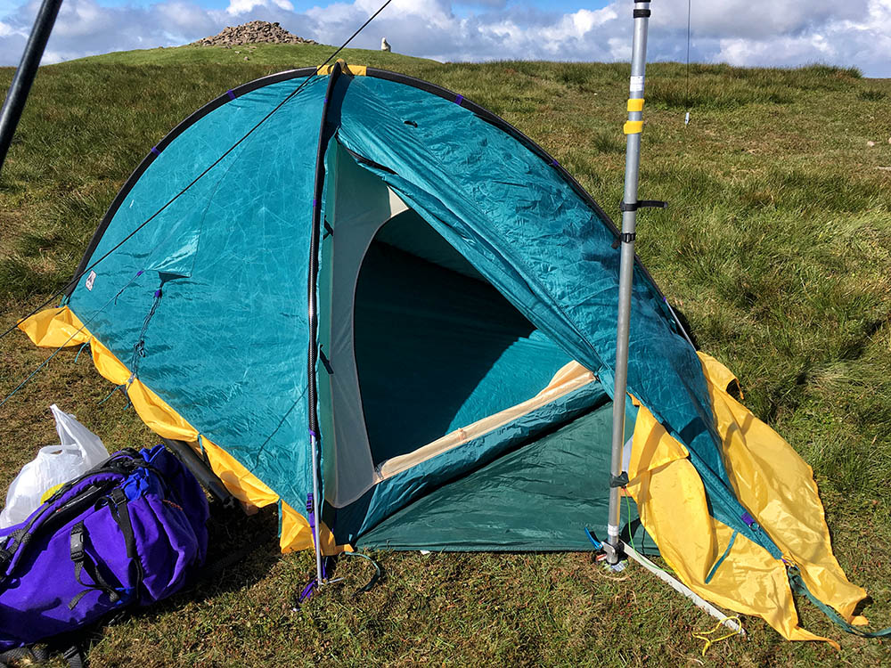
Shack up and ready for us:
Shack views don’t come much better than this:
To keep us sustained we have proper contester food:
Once on air we scanned the band looking for a slot between the strong VHF NFD stations. We found one a fair way from the strongest ones but one near from the North lifted our noise floor each transmission and made receive pretty tough. However we persevered and activity seemed pretty good though DX apart from Scotland was scarce for us.
We like to run mostly and keep the work rate up to keep the QSOs coming in and search and pounce when it goes quiet. The last hour was very slow after the NFD closed down but on the up side we had a receive back! We managed 120 QSOs which we were pretty pleased with and a best DX of nearly 800km to the Orkneys which was great. And he was booming down too. No ON or PA at all though.
The 2nd event in this series of contests coincides with the Practical Wireless QRP contest so we decided we would do both. This contest starts earlier than most of the other Backpackers event so it was an early start for us, or I should say even earlier.
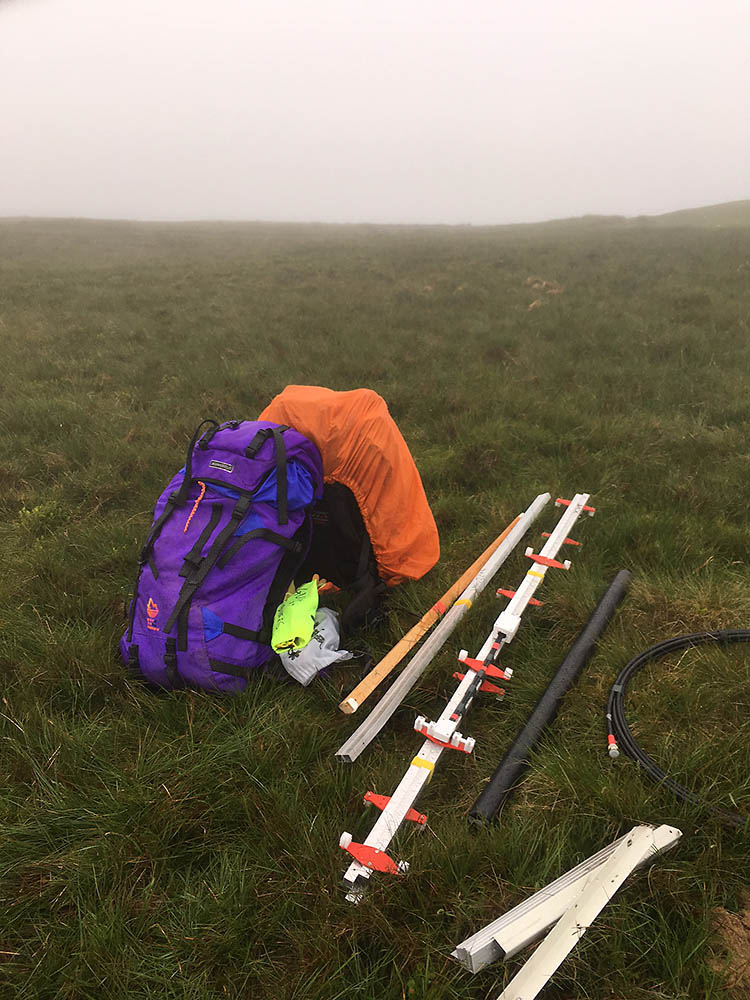
The weather this time was fairly poor. Lots of rain and quite windy. So we arrived on the top pretty soaked through with terrible visibility and a pretty dense low cloud.
The summit site is pretty exposed so if there is any wind at all anywhere, it’s usually very windy on the summit. We were ready for this though. The lightweight mast I have built was made in 3 sections and purposely designed for such an occasion. For lower less exposed use in contests where we are OK to use its full length all three sections are extended and we have a set of guys for each section. (the lower guys are really only there to hold it up while we extend it etc). But for the backpackers series section 3B we are only allowed 4m high, which just so happens (it was designed that way really) to be the height with the mid section extended. This means we have the option of double guying the highest section of the mast. We have separate pegs for every single guy as this negates the need for knots and saves us set up time by just putting the peg in the loop, and putting the peg in when the guy is taut. This also means on a 4 metre mast we have 8x 550lb breaking strain guys on 8 decent sized pegs, so despite the scary wind noises when inside the tent the antenna is pretty safe.
Double guys shown here (one on left is the lowest set up guy going to a tiny tent peg):
Once in the tent we were pretty cold thanks to the liquid cooling we were enjoying. We’d allowed plenty of time to deal with any unforeseen circumstances or issues setting up in the bad weather so we had time for a few warming cups of coffee.
Once under way we forgot about being cold and set about the job in hand:
We got pretty decent activity in first hour or so, and to be honest not bad in the first 4 hours, which is all of the Backpackers contest. However DX was rare we managed a French station at Calais and one Belgian station. It was nice to point to Guernsey hoping to pick some mults up and within 5 minutes we got one, thanks for that! The last 3 hours to make up the PW QRP entry were best described as dire. Without the CQ caller I made I am pretty sure we would have quit and gone home. On the plus side we never heard anyone with a higher QSO count, but PW is a square multiplier contest and I feel we are going to suffer with a low square tally.
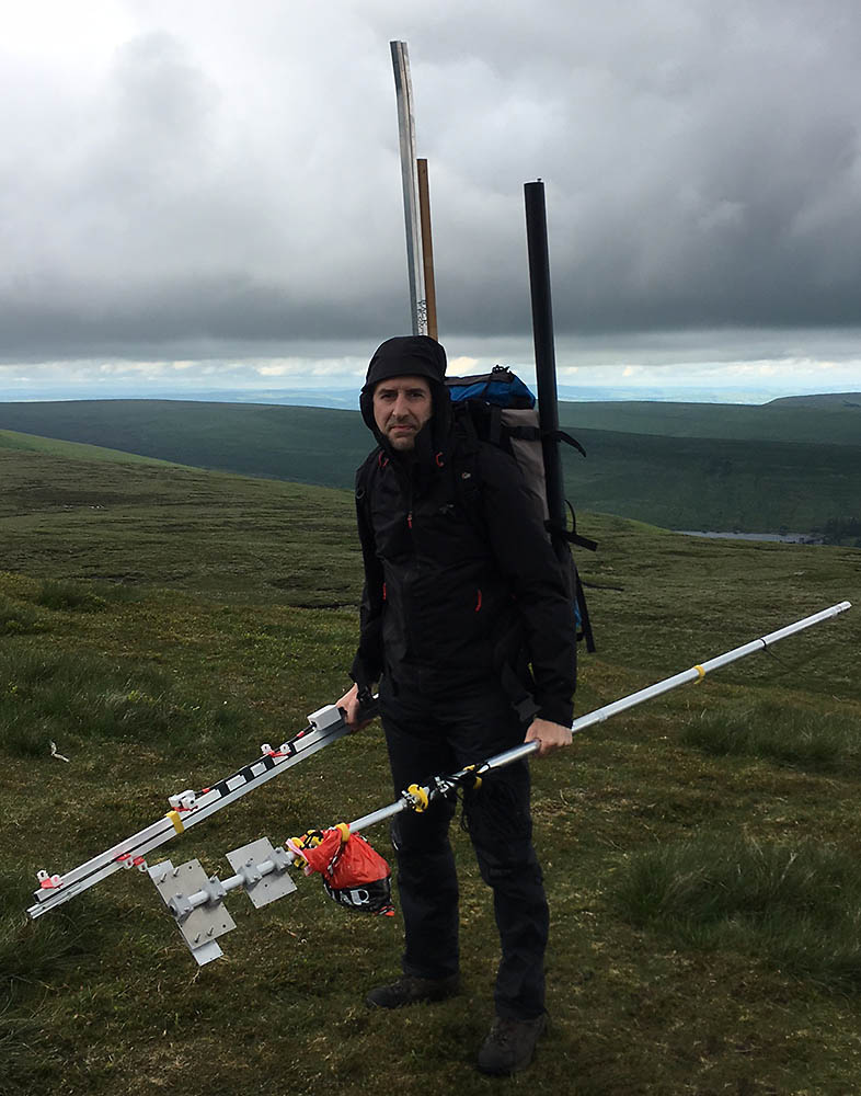
There was no post contest looking around and chatting. Radio straight off and try and pack up before the looming black cloud making it’s way towards us arrived. Here we are ready to roll (taking turns holding the mast for the camera):
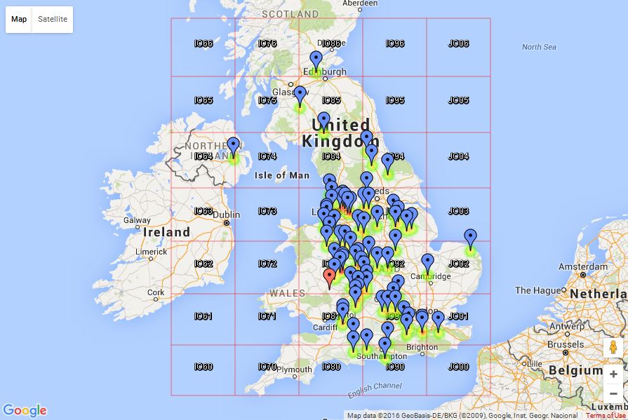
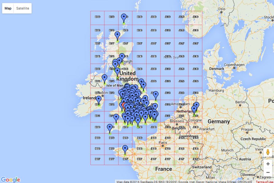
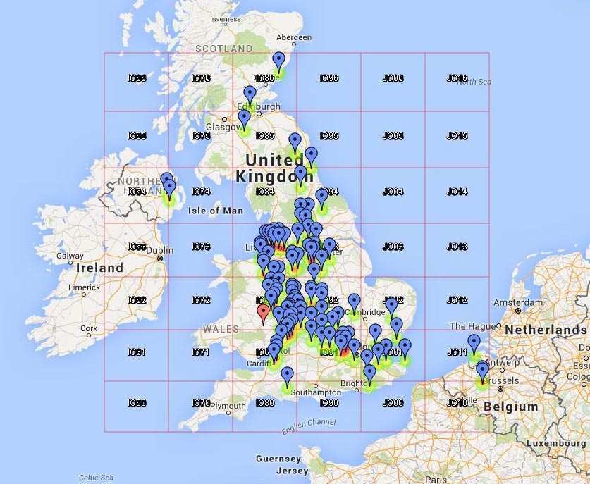
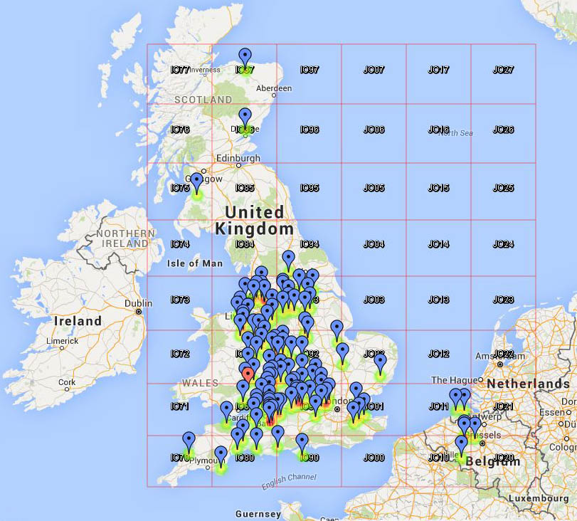
QSO map:
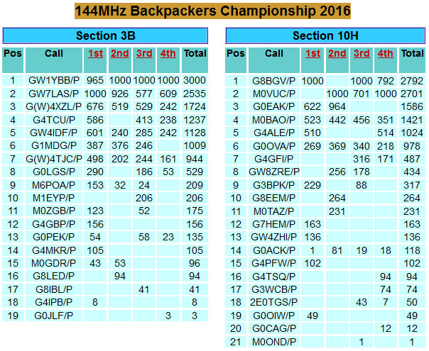
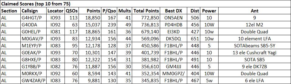
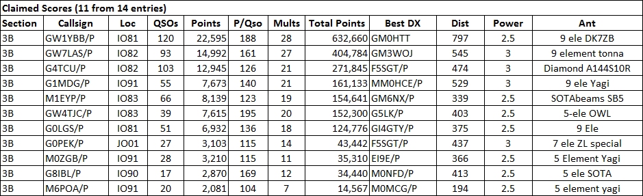
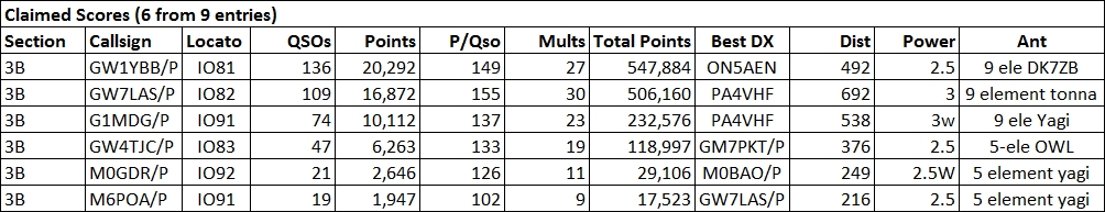
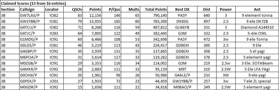
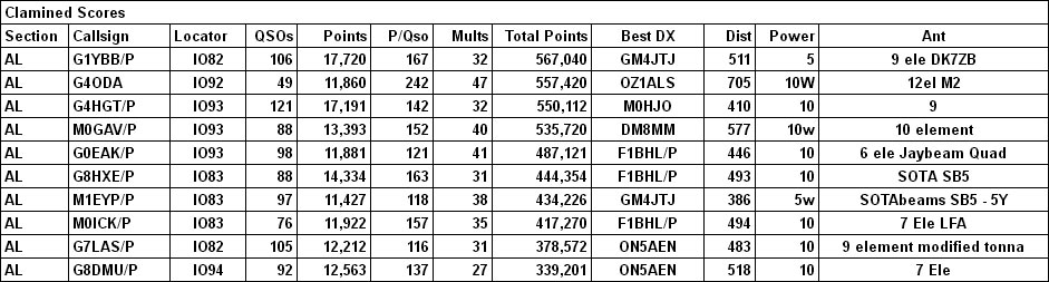
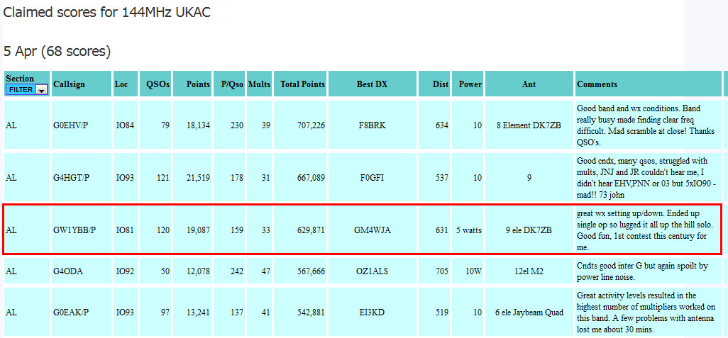
Claimed scores:
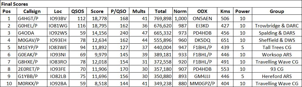
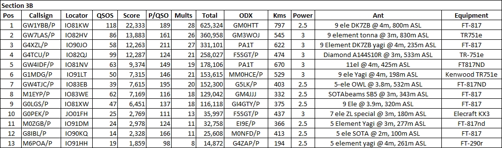
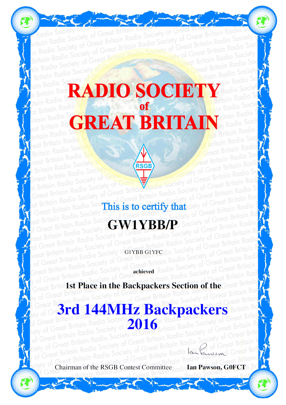
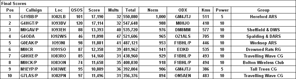
Results:
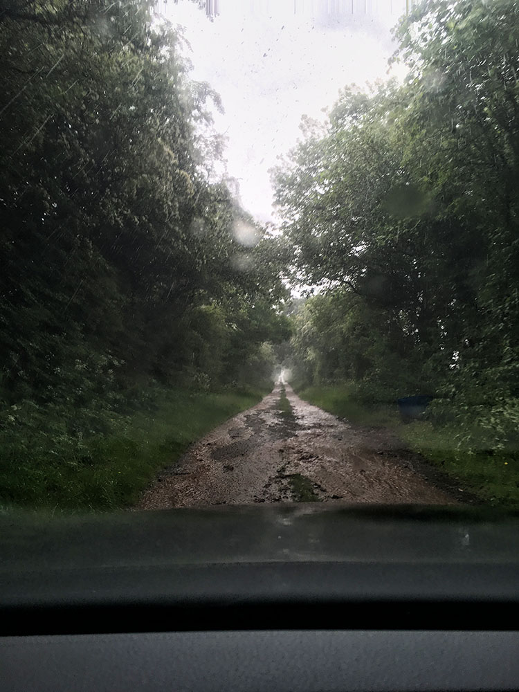
This session I had company in the shape of Paul G1YFC to help set up and operate. Another pair of ears is always welcome with the weak stations or when we are suffering from QRM from other stations. On reaching the bottom of the ascent of the hill we were greeted by flashing flooding from the lashing storm that was hammering the car. The lower roads where more level had 4 to 6 inches of flowing water over them and even the higher steeper sections were a brown rushing river about 1 or 2 inches deep. This is a picture of the very last section of hill with hardly any catchment area above it:
Once on site we sat in the car to wait out the heavy rain. It eased a little so we started to put the mast up but the rain picked up and it felt like someone was pouring a hosepipe down the back of my non waterproof trousers so we abandoned ship to the car. It eased again so back out we went and this time it stopped and the sun came out. By the time we had the antenna up we were bone dry from soaked through.
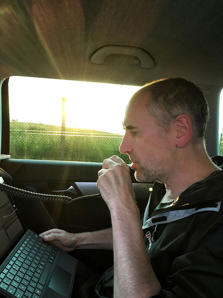
We had a few QSOs before the start and fisnished the last rag chew with the first QSO in the contest but found it a slow start. Conditions seemed quite odd and we could hear a lightning strike crash every now and then for most of the contest but we didn’t see any. Paul had time to take an arty low sun shot of me in action:
We also had an interested visitor:
Anyway, we got 105 QSOs but didn’t work one single European station not even Frank PE1EWR who always calls us. Although our QSOs were respectable and points per QSO also not bad, we just didn’t have the multipliers.
This was the series of contests I have been building the lightweight and portable antenna system for. I knew exactly where I wanted to operate from and the new (to me) super lightweight Yaesu FT-817 radio and the modern Lithium batteries have made it a possibility for me. Most of my previous contesting in the 80s and 90s was done in the Black Mountains below Pen-Y-Gadair. It is a great site for the non multiplier contests but because we were below the summit we always lost out on multiplier events. I always wanted to operate from the summit but with our equipment then it was a no go for us with no 4WD and even a landrover would struggle to get there.
But I can walk there! Well I can with Paul G1YFC to help carry the gear.
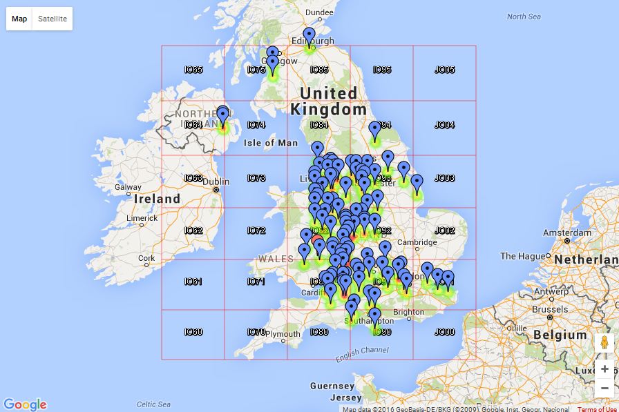
Here I am loaded up:
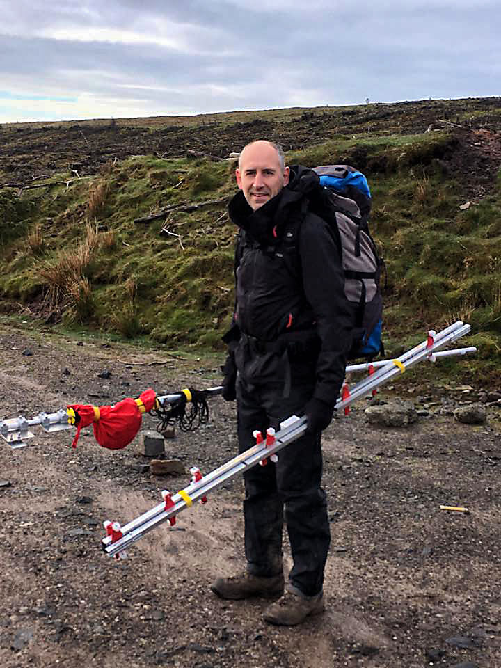
And Paul with his load too:
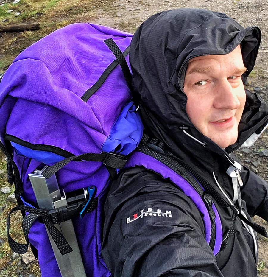
Nearly at the summit:
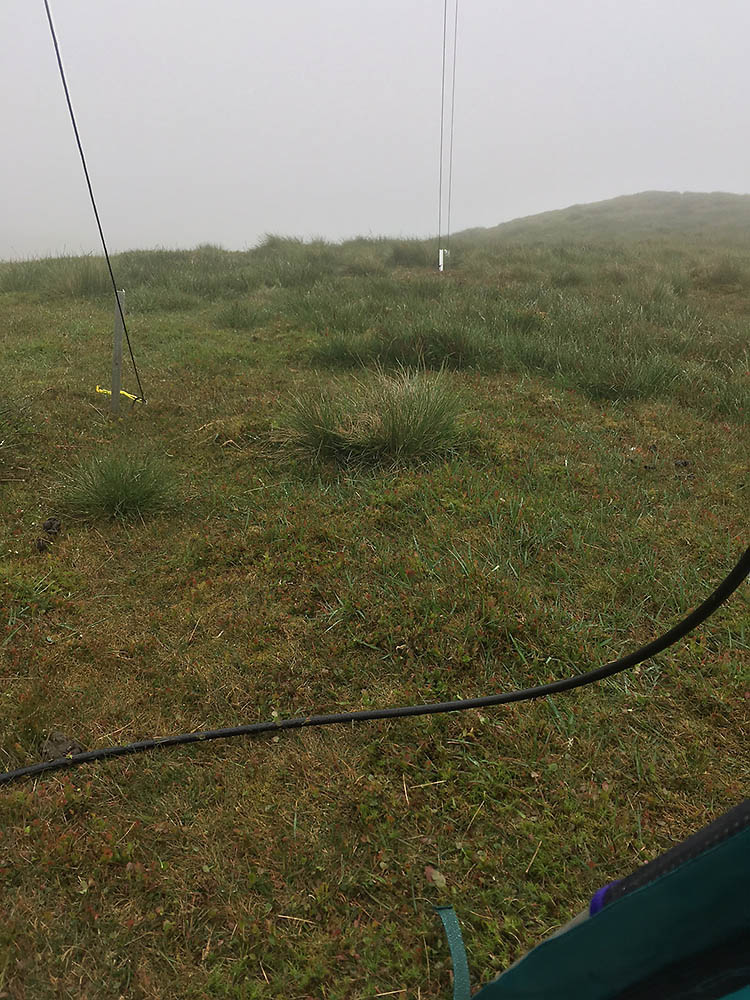
The weather today was practically perfect for contesting on top of the exposed summit, unlike the day before when the winds would probably have made it impossible to get my lightweight mast up safely. We managed to get the antenna set up before a light shower and soon had my mountaineering tent up too. We set up away from the summit cairn to be out of the way of walkers but also to be above the steeply falling East facing side of the mountain to make the best use of the ground gain:
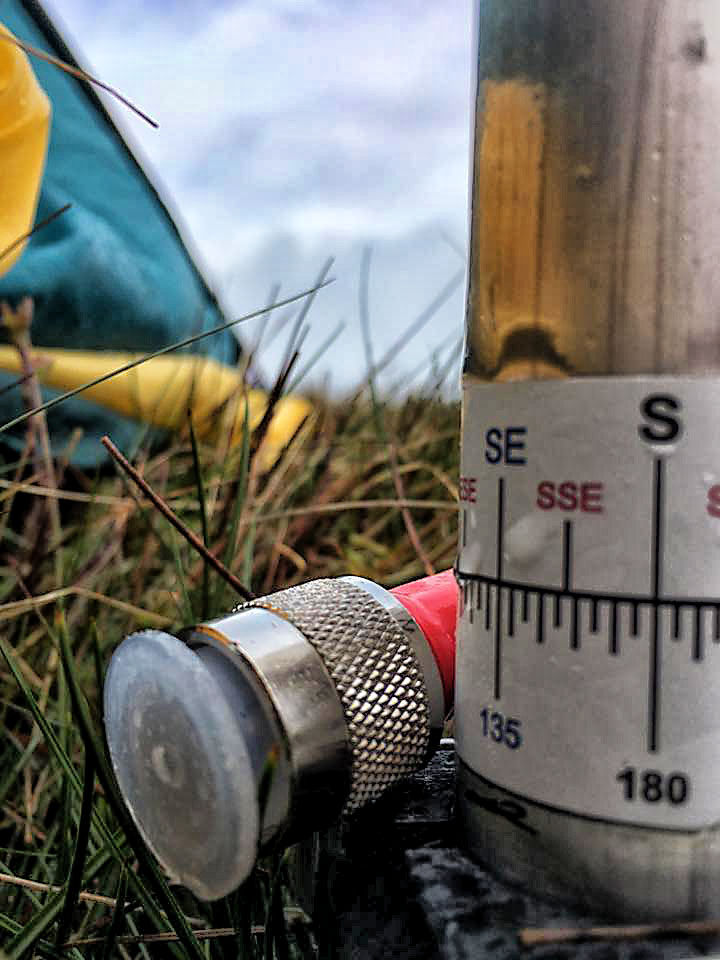
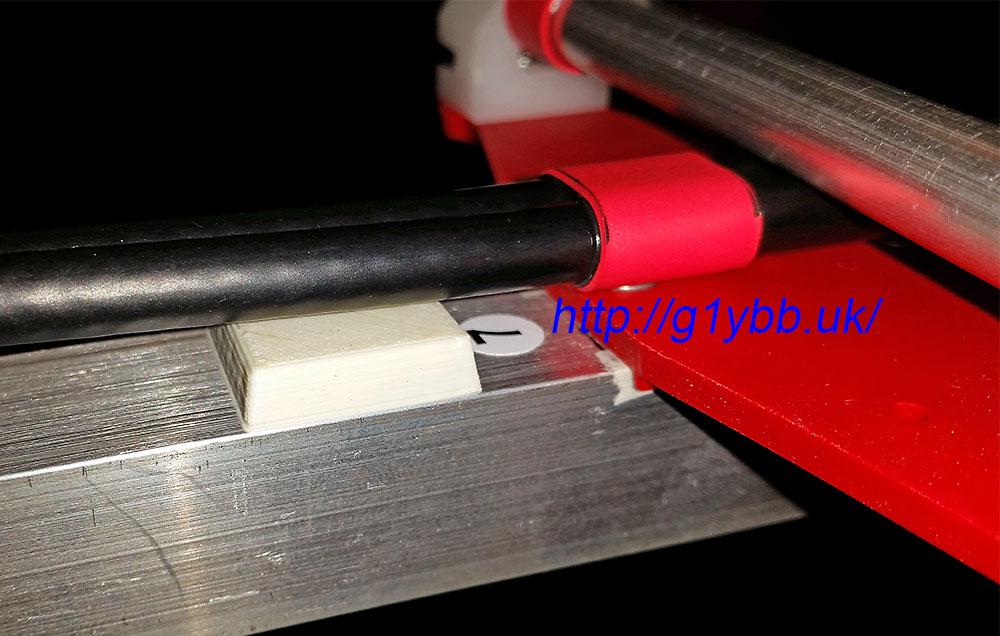
Paul took an arty one of my direction label and the end of the coax:
Once the radio was connected up we scanned the SSB section of the band to see who was about and to find a free frequency. There were some strong fairly local (as crow flies) stations below 144.300MHz so we went higher to be clear of them. I noticed I could hear one station CQing 50KHz away so decided a 100KHz away would be a good plan. Once it hit 11:00 we were off. About 90 minutes later Rob GW7LAS/P popped up and after our exchange informed us we’d kicked off an hour too early. Doh! Disaster. We worked some good multipliers and quantity of QSOs in that first hour, for no avail. There was nothing for it but to soldier on and make the best of a bad job.
Later on we had a sharp rainstorm and with it came S9+ of rain static. So strong the station that we could hear 50KHz off his frequency was only just readable above the noise. Luckily it died back down after a while. The last couple of hours were pretty hard work beaming north for some Scottish points proved fruitless as did beaming to Eire. We did beam down towards Guernsey hoping for some GU and maybe a French station that seems to be on often in the UKAC events and were pleased to pick up Guernsey and Alderney almost straight away.
We finished with 121 QSOs of which 79 were in the qualifying period. We lost 9 multipliers from 6 QSOs in that first hour alone! However we managed to salvage a reasonable claimed score of 783,300 points which put us just in 2nd place in our section. One more average QSO would have taken us to 1st!
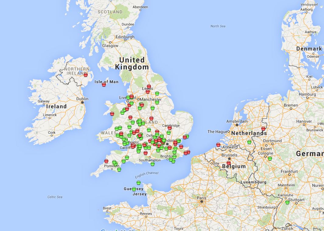
Here is our QSO map, valid QSOs in green, invalid in red. We lost some good distance ones and multipliers too:
Our claimed score was encouraging though. Hopefully Rob GW7LAS/P made more logging mistakes than we did, one decent lost QSO more than us would mean we would swap places:
Results showed we couldn’t overtake Rob after all. So close yet we could have done so much better. BIG lesson learnt there! Full result list (PDF)
For this next session of the the UKAC series I decided to use an old site that was the site of my first ever 144MHz VHF contest when I entered the PW QRP contest with Kevin G1VDF. I chose to operate here as I was hoping to get back earlier as getting into bed at 1am on a work night was a bit late. The drive is slightly longer but it is a drive on site so packing away hopefully would be quicker.
Where I decided to set up was a little cramped and awkward to raise the mast on my own so it took longer than it could have. However I did manage to get all set up and on air a little before the kick off although with no real spare time for any photos this time.
I could hear some seriously strong stations giving me some interference so I tracked them down to check they weren’t in the field behind me or something similarly close. They weren’t but they did report I was giving them issues with splatter and sounded like I had far too much compression on my audio. This was the first time out for my new build of the BX-184 CQ caller which I suspected might be set too high in the mic. As I didn’t have the right tools with me to do anything about that I tried to cut down the overdriving by turning down the SSB mic gain down a fair way. This was said to help but not solve the issue completely, though I was receiving the complaining stations so strongly the signal reading never came off the ‘stop’ between their words even. I changed my operating frequency for a further 10KHz away from them to try and help.
Once under way activity was quite good as last time but generally although signals all seemed to be really big I didn’t really get as many more distant stations. I’d hoped to make use of the ON4KST chat like most do for finding multipliers but I was not getting any cell coverage to get online which was a shame. I did manage to find two new GI squares searching and pouncing though again missed some other ones. It’s tough to know how long to spend away from the running frequency searching and pouncing!
My QSO map for this contest:
My QSO count was 2nd highest and my claimed score put me in first place in the low power section. However it was close at the top and adjudication could easily scupper that:
The results came in quite quickly this time and I was pleased to see I was still top out of the 85 entries in AL section! I lost 5 QSOs for errors but luckily others lost some too and I stayed top:
Oh, and I was in bed by 11.45pm, result!
As I have always operated way more as a portable station than a base station I have operated from the car many times and in many ways. Some not as comfortable as others that’s for sure. It gets tiring twisting to one side or hunching over. In the end I came up with a simple solution for me that enables me to easily set up and have space, and be comfortable operating, which is important if you are spending a long time operating like in a contest.
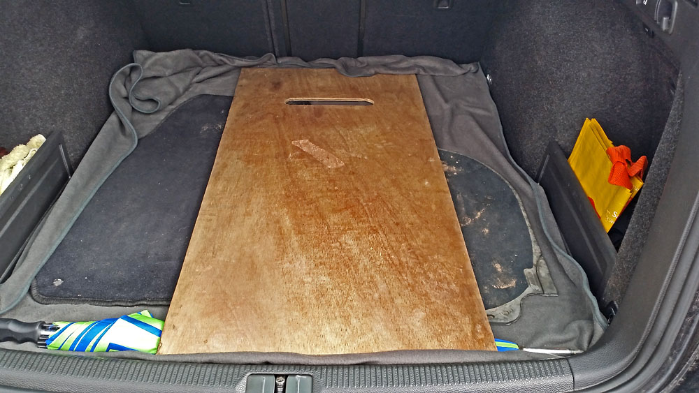
Basically, a plank of wood!
More accurately it is a small sheet of plywood sized and modified for purpose to make a flat table in the car to carry the radio and any ancillary units like batteries, PSUs or amplifiers etc. It’s strong enough to support a 4CX350 based 200W VHF amplifier.
The sheet is sized wide enough to fit in most normal cars and long enough to reach from the top of the dashboard to just past the back of the driver’s seat. There is a slot cut to allow it to slip over the steering wheel:
I keep it in the boot ready to go as it doesn’t really take any space. I just take the head rest out of the driver’s seat and sit the board on the top of the seat. The slot for the steering wheel allows the board to sit on top of the dash and adds a level of security from catching a sleeve on a corner and knocking it off. In my shiny new car I just add a towel over the steering wheel and dash and another on top of the seat to protect them from any markings. The two head rest entry points and top of the curved dash make a tripod style stable platform. And the weight of the radio and batteries keep everything steady.
I use my backpacking batteries because I don’t have a DC feed at 20A to the car battery for the radio and I don’t have to worry about draining the car battery if a pileup comes my way.
I pull the steering wheel all the way forward to drive anyway, but this means the wood extends back enough to sit normally in the back seat without even moving driver’s seat and I can sit with my back against the back seat (rather than hunched forward) comfortably and operate. In fact these days as you see, I have the tablet on my lap. The most comfortable car portable operating I have found, and I have done a lot over the years!
This is about the 4th or 5th car this board has seen action in and it is now into it’s 4th decade (with about a 2 decade break).
After hoping to enter the previous two sessions of the RSGB 144MHz UK Activity Contest series but for various reasons failing to get on the air this time I finally succeeded. It’s 18 years since my last VHF contest. This time I could try out my newly finished and as yet untested on air 9 element DK7ZB yagi and lightweight portable mast.
I checked the past year’s results to see if my old (from back in early 1980s) site was being used in the UKAC series. As it didn’t seem to be I chose to try there for this contest.
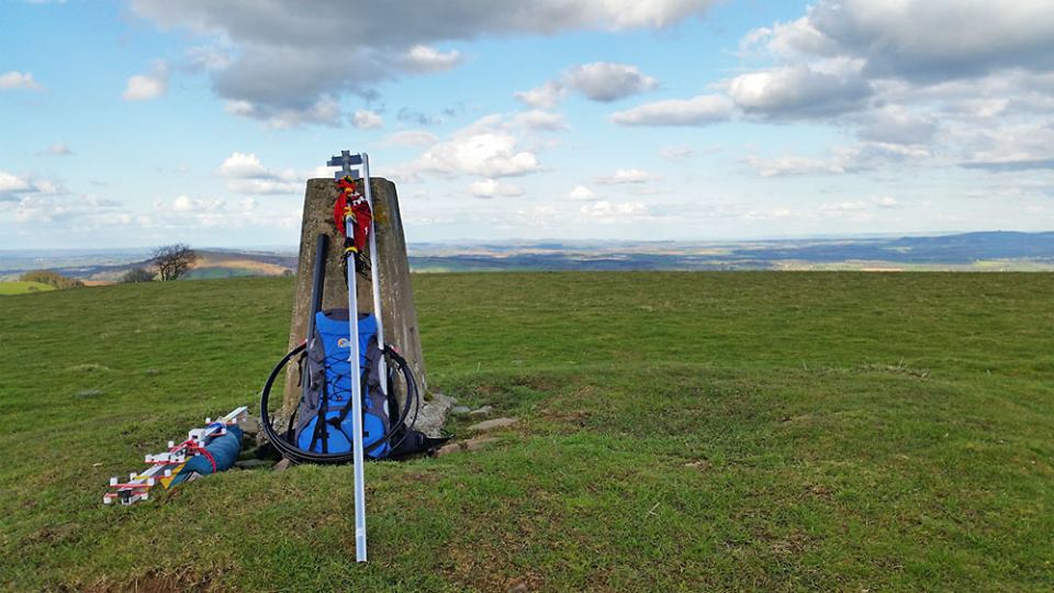
The original plan was Paul G1YFC would also come up for the contest (we won our last contest in 1998) but he couldn’t make it so I slogged up the hill with all the gear on my own to the trig point on Graig Syfyrddin which is at a height of 423m which a clear take off though has the 400m higher black Mountains West of it:
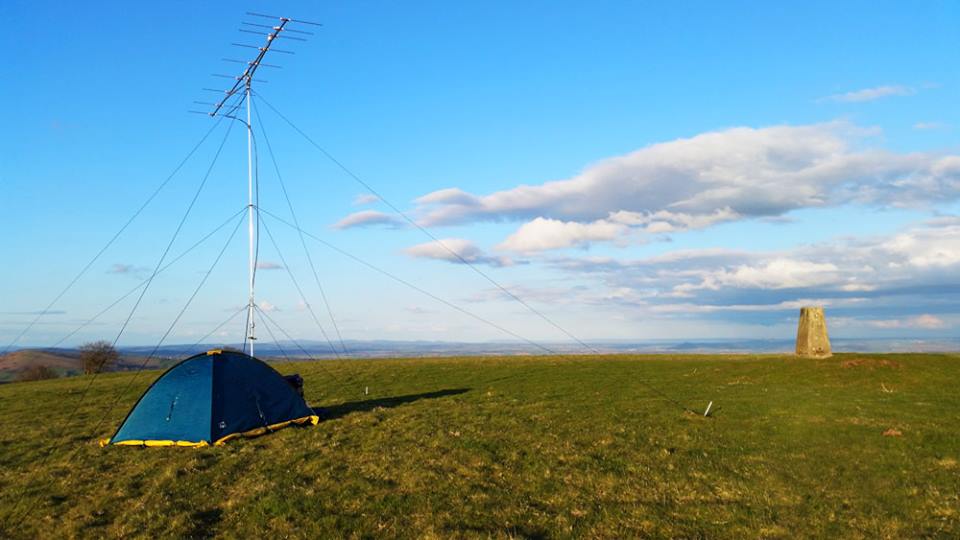
Literally every radio item I would be using for this contest was new to me since the last contests I did. It was a pretty calm evening so setting up was fairly straightforward and I soon had the mast and tent up:
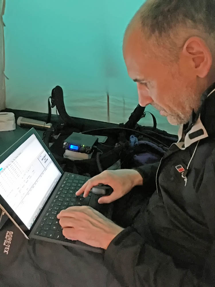
Once I had the Yaesu FT-817 connected up and the tablet fired up I worked a few stations before the contest getting good reports from my QRP station which was good to hear. I did learn it’s much wiser to operate from a hill you can pronounce the name of though. One quick check outside before the contest starts revealed a nice sunset:
Once the contest started activity was pretty good. For the first hour or so I was exceeding 1 QSO per minute and getting great reports. Things did slow down a bit and QSOs came in little bursts of activity. I made use of the 2nd VFO for some search and pounce but was mostly running. Logging was done on my Surface Pro 3 using Minos by G0GJV. What I should have done I think was also try the ON4KST chat that everyone uses. It actually never occurred to me on the night. This was a great shame as I missed a couple of leading big gun stations somehow that would have given me some valuable new multiplier squares. Anyway I got 120 QSO in total which seemed respectable.
Here is my QSO map:
Packing up as quickly as I could by headtorch I headed down the hill almost running at some points. Even rushing it was midnight when I reached the car and 1am by the time I got to bed.
My claimed score (before adjudication) put me in 3rd place in my section. 4 multipliers (2 UK new squares) would have put me top! Missing those big station multipliers was very costly indeed!
Overall I am very pleased with the first go out this century. It was meant really as a practice run for the forthcoming 144MHz Backpacking series of contests and also the PW QRP Contest which I have always been a big fan of. The equipment all seemed to work well apart from one small temporary issue with the keyboard on the Surface Pro 3 failing to respond which was very inconvenient. I did get it going but without know how or why it stopped working.
As I was planning to resume 144MHz contesting but this time full backpacking style I wanted a decent beam that was suited for repeatedly assembling and disassembling. I have a Cushcraft Boomer and also a pair of homebrew DJ9BV yagis but neither are really ideal for the job. After nearly two decades away from radio yagis have moved on and researched showed the DK7ZB yagis were very popular. His designs seemed ideal for my purpose.
I settled on the 9 element long yagi as it is not too long but with decent gain and also has a good flat SWR curve. The RSGB Backpackers section we wanted to participate in only allows one antenna so stacking shorter yagis was out.
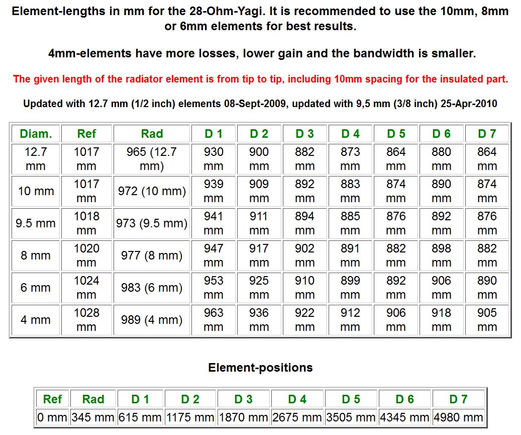
The dimensions are available on Martin DK7ZB’s site:
I went for the 10mm elements as a compromise between size and weight and best performance. I was also able to find 10mm clips to suit my intended design.
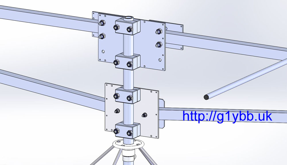
You can buy some of the DK7ZB yagis ready made and also in kit form, but I didn’t really think the parasitic element mounting methods were ideal for repeated building especially in cold weather. Also the driven element was a problem as it’s not ideal at all for disassembly. There was one example of a driven element designed for taking apart on DK7ZB’s site but I couldn’t find any parts like they were using. I was already building my own lightweight portable mast so I decided I may as well design the yagi from scratch too. So I modelled the full antenna down to every nut and bolt in 3D CAD software. This enables me to know exactly what materials I need and also predict pretty accurately the weight, bearing in mind I plan to backpack this up hills:
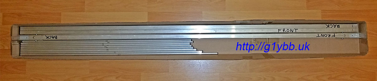
To source the main raw materials I found that it was cheaper to buy from https://shop.nuxcom.de/ in Germany than anywhere I could find in the UK! I went for the 20mm square boom and 10mm elements. My 3D CAD model told me I wanted two sections of boom 1.72m long and one section 1.62m long. (After ordering I noticed that is the same lengths Attila uses in his 9 element kits!) I didn’t go for a kit as there were several parts in the kit I didn’t need and I wanted to order a few spares of the elements just in case I cocked up some of the cutting. Nuxcom sell the boom in 1.5m and 2.0m lengths but the 2.0m lengths cost more than double the shipping, so I asked Attila if it was possible to buy 2.0m lengths but have them shipped in two pieces, 1.72m and 28 cm lengths. He did this for me at no extra cost which is good service. The offcuts would be useful for doing tests later.
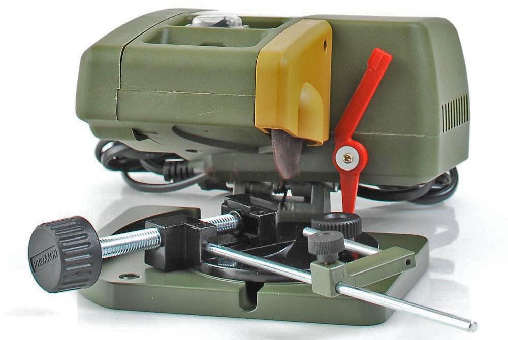
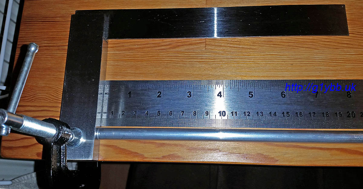
First building task was to cut the parasitic elements to size. Although I’m pretty good with a wood saw I’m a bit rubbish with a hacksaw and I didn’t want to use a pipe cutter as certainly for the driven element I needed no deformed ends to the tube, so I managed to borrow a mini circular disk cutter like so:
With this I was able to make nice square cuts. To measure them I used a metre ruler (tape measure for the reflector-checked against the metre rule first) butting both up against a stop to get an accurate measurement. I checked that the first mm was a true mm before starting as some rulers have a dubious first mm:
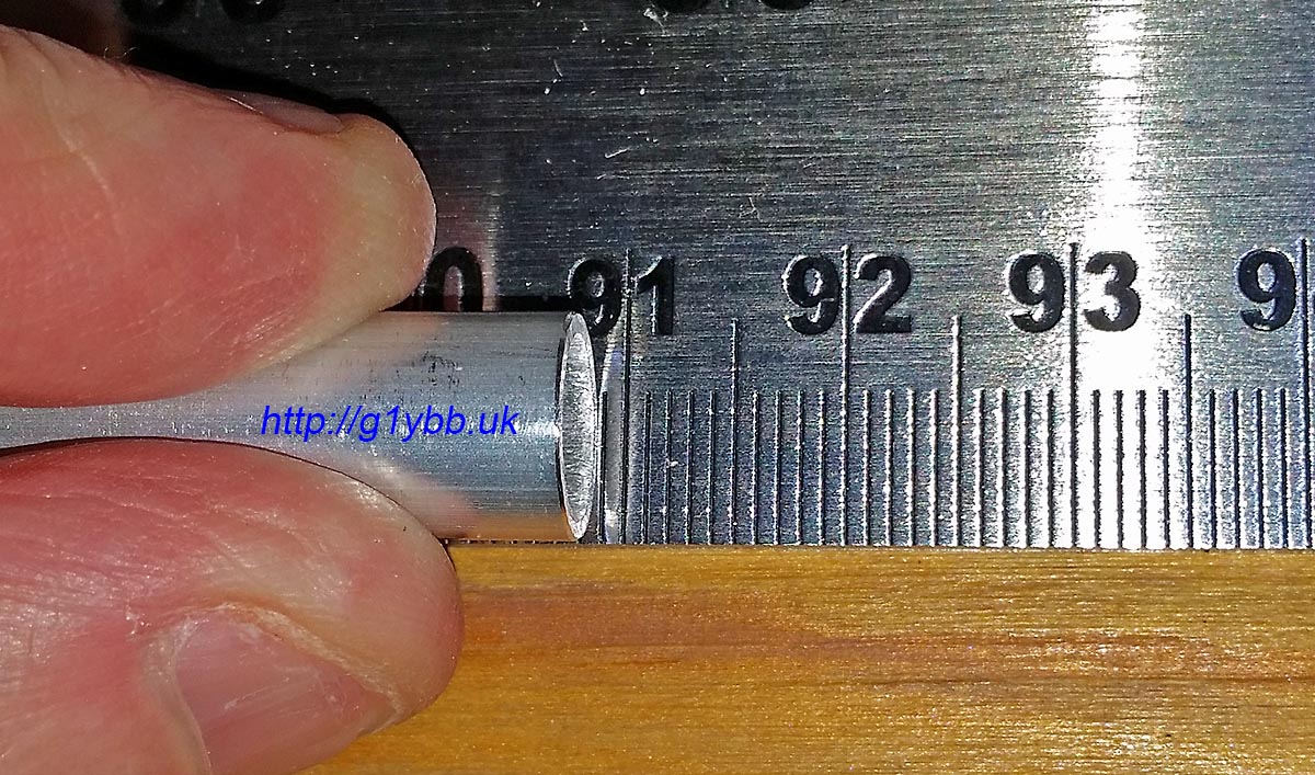
And checking D2 (ever so slightly short if anything by a fraction of a mm):
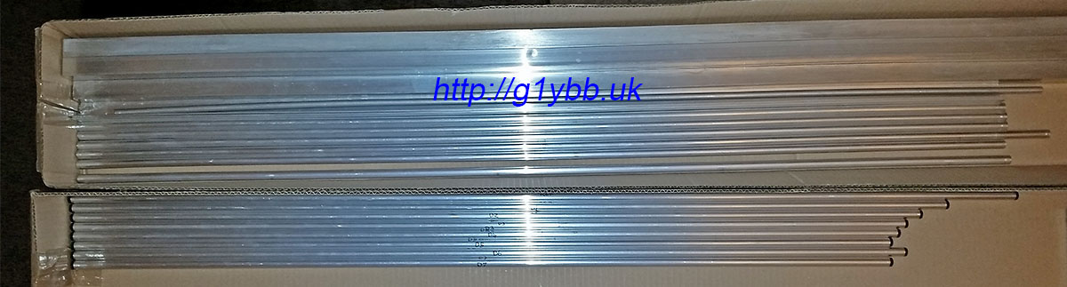
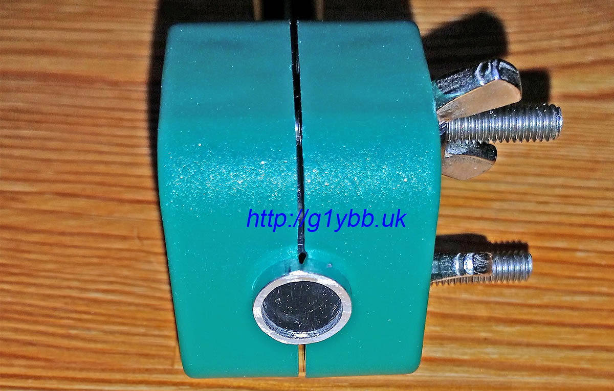
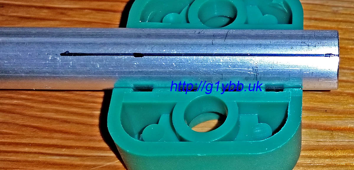
After cutting the parasitic set I fitted end plugs from Nuxcom for a nice finish. (Elements in bottom box, spare elements and boom sections in top):
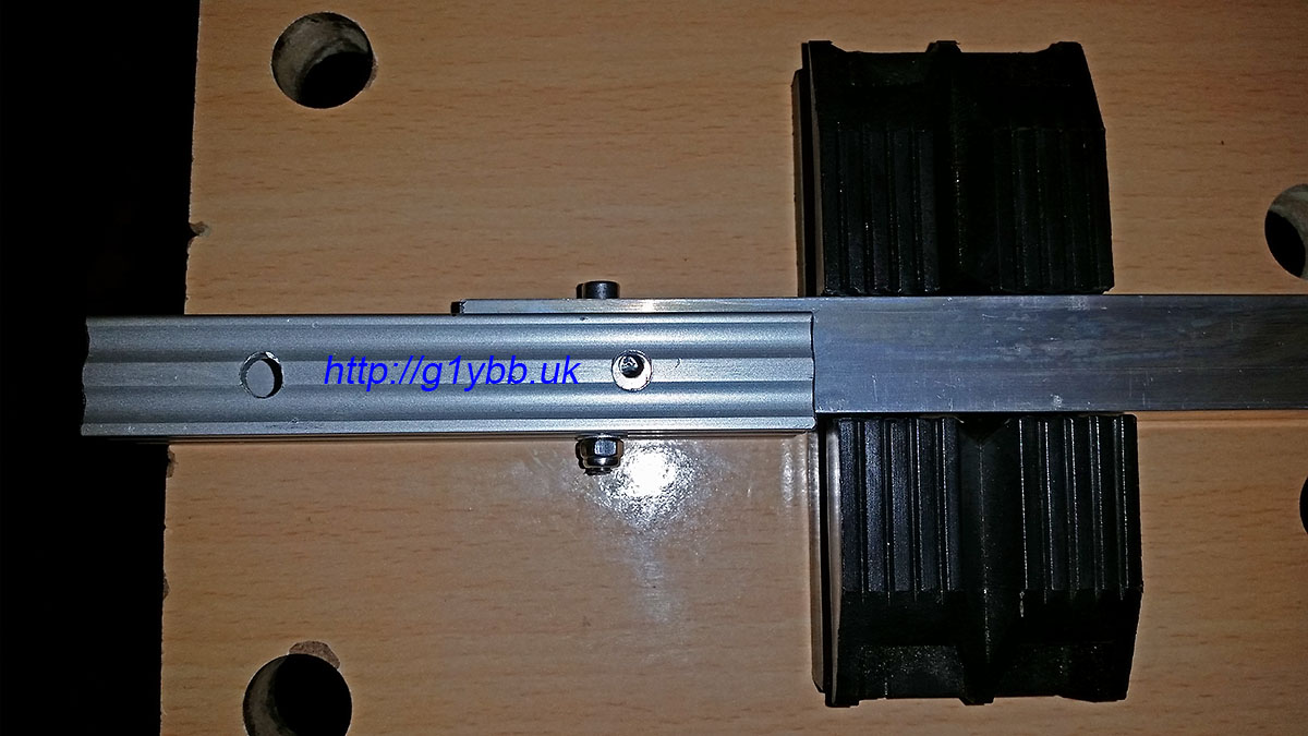
Next to assemble the boom. I bought the Nuxcom boom joiners and I must say they are very well recommended. The fit onto the 20mm boom sections is a snug push fit and the extrusion is thick enough to be strong yet still light. I got them with the M4 bolt and wing nuts. The one thing I didn’t like so much was the massive hole for M4 which was 6.5mm diameter. However, once I modelled up the joiners and dropped them into the antenna assembly I could see that a 4mm hole at the top of the 6.5mm hole would be pretty much bang on centre of the boom, and mean the boom could not move up in the joiner. I also added a vertical bolt on each side of the joiner too as shown below. That meant the boom section was forced into the joiner tightly ready to drill the holes. I drilled from each side, using the 6.5mm hole as a stop for the 4.0mm drill bit:
The above picture is showing the boom joiner fitted to the centre section. Both joiners are fitted to the centre section and will stay there permanently so I have used socket cap heads and nylocs, all stainless steel, bolts cut to minimum length. (The four supplied wing nut bolts will be used to attach the end sections on the hill top). With both joiners fitted, the centre section then is pretty much the same length as the outer sections (by design). I also bought the square boom end caps from Nuxcom to finish them off nicely:
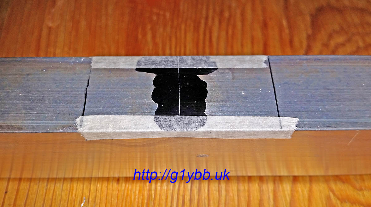
The boom was then assembled in my hallway and the centrelines of the element positions scribed on. I used a tape measure masking taped to the boom to ensure it never moved and starting at the 100mm mark on the tape measure to eradicate any errors from the tape measure hook end.
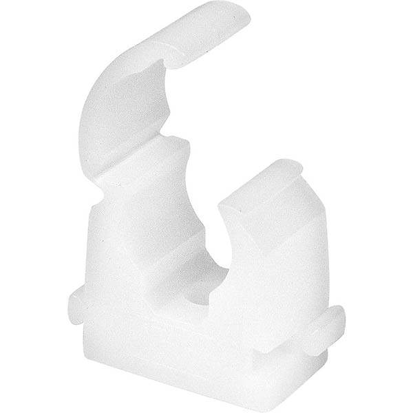
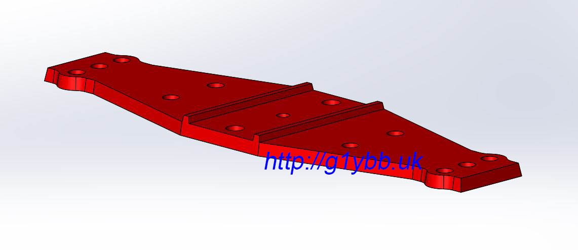
The element clips I needed to find something that was quick to mount the elements and remove them again. The typical single bolt through the centre of the elements I didn’t fancy as it was a bit fiddly especially with cold hands on a windy hill top. My friend found these 10mm pipe clips that were ideal. Snap in and lock, and easy to open again to remove the elements. They will have a finite life but my test piece has had dozens of cycles and they come in a bag of 100 for under £6: Another plus point of this is the element centre is a reasonable distance off the mounting surface which means I had good scope for getting the driven element to be on the same plane as the parasitic elements. I just need some suitable plates to mount these on nice and squarely on the boom. My friend offered to injection mould me some rather than my trying to accurately drill out several plates exactly. So I modelled up a mounting plate to be made from glass fibre reinforced nylon which is extremely strong and stiff for its weight. The image shows the underside. The two ridges are to locate on the square boom:
Soon in the post came a parcel of element mounting plates. We decided riveting them on was a secure and lightweight fixing method. The two location ridges on the bottom had a slight amount of play when offered to the 20mm boom which of course would be amplified by the approx 100cm elements so I fitted two tiny strips of masking tape which made the plates a perfect fit. Once the rivets were in it doesn’t matter if the masking tape decomposes away:
The small hole in the very centre of the element plate is a sighting hole to align the element in it’s correct position on the boom. This was used to line up to clamp the plate on for the drill of the first rivet hole:
Once the first rivet was fixed, the clamp was no longer needed and the 2nd hole drilled and riveted:
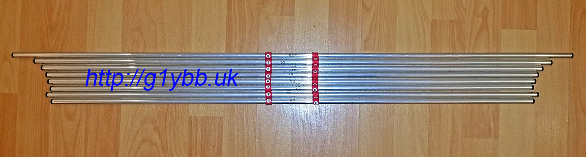
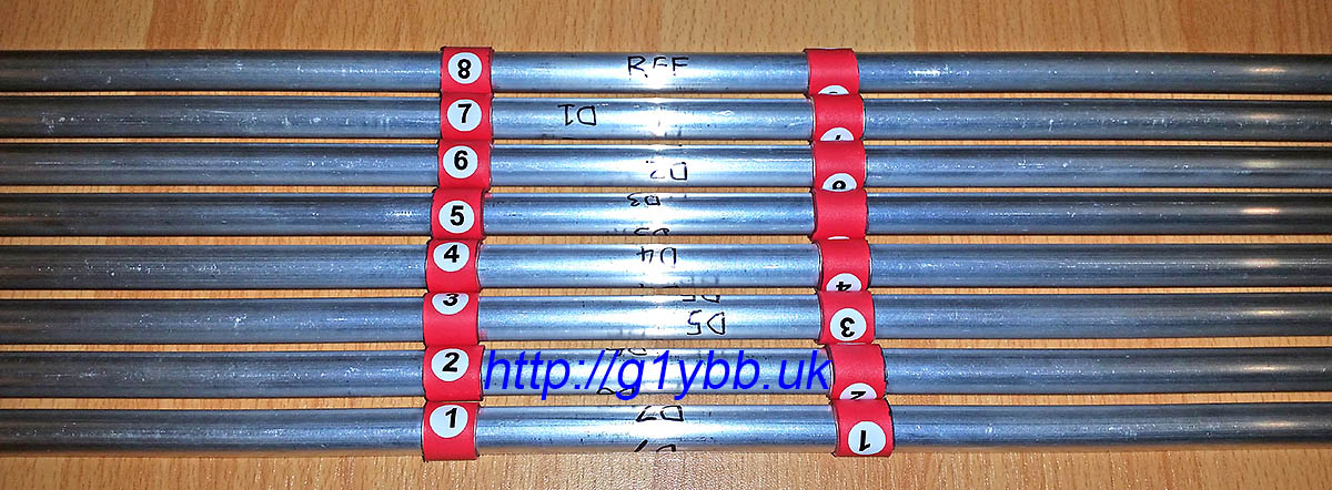
Then a simple case of fitting the 10mm pipe clips and snapping in the elements in the right place centred on the boom. In order to easily locate the element centrally on the boom with out any time consuming I fitted to each element a piece of adhesive lined heatshrink to be positioned between the clamps. I also added some marking numbers for the 8 parasitic elements, numbered 1 to 8 from from to reflector:
Now the easy bits are done, time for the driven element. This was the biggest head scratcher on how to make it suitable for repeatedly taking apart and assembling. I needed to come up with a method that both left the electrical connections to the driven element halves but also enabled me to remove them for transportation. This meant a split in each half of the driven, but how to attach it?
I decided to come up with a system of employing a ferrule in the driven to join the two halves. With some custom made parts it would also be mounted on the same element mounting plate as the parasitic elements and is the reason the element plate is larger than a typical one, although that was also good for rigidity and build accuracy.
When I ordered my 10mm element tubing from Nuxcom I also ordered 1 metre of 8mm tubing to do this. But there were two issues with this. The first was this was the only piece of tubing that arrived with a bend in it. If I had planned to use it as an element I would have had to reject it. As it was I could cut out straight parts to use but the 10mm diameter 1mm wall thickness elements have a bore of about 7.92mm and the 8mm tube an outer diameter of about 8.10mm. No chance of a fit. Out with the calculator and it soon transpired 5/16″ should be a perfect size. I bought some T6 grade aluminium from eBay and it was a perfect fit. Sliding with no slop at all.
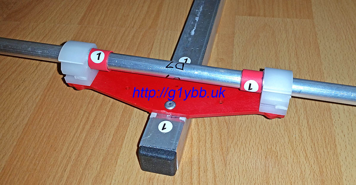
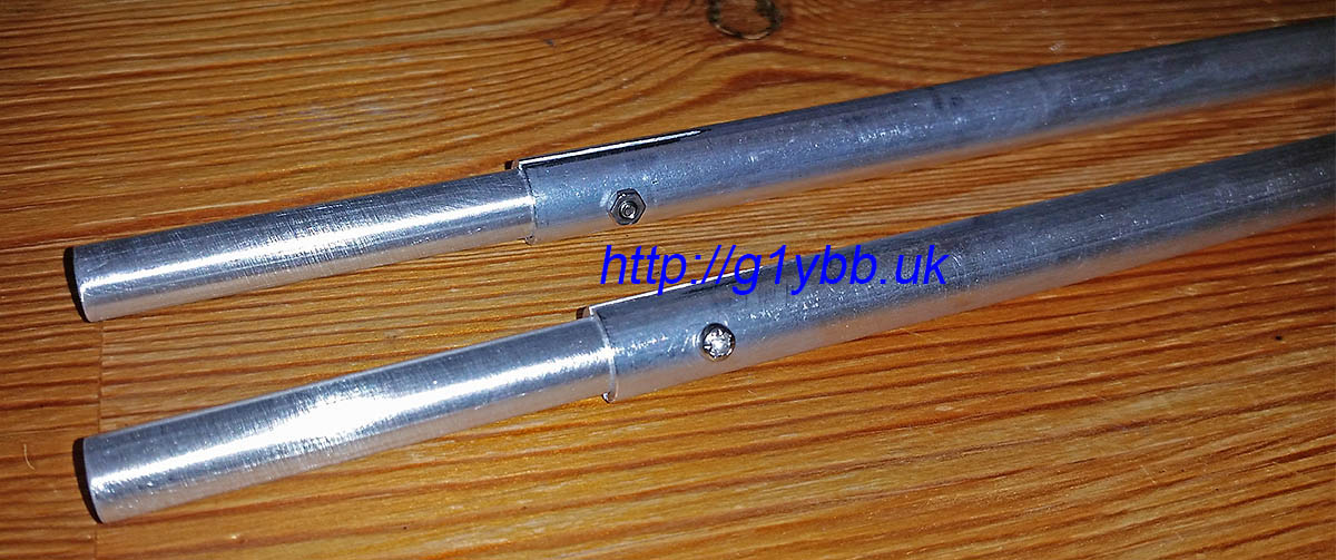
To cut slits in the 10mm tube to compress it with clamps to grip the ferrules I used two 10mm element clamps to mark a dot each end and each side of the clamp and joined them up to make cut lines to follow:
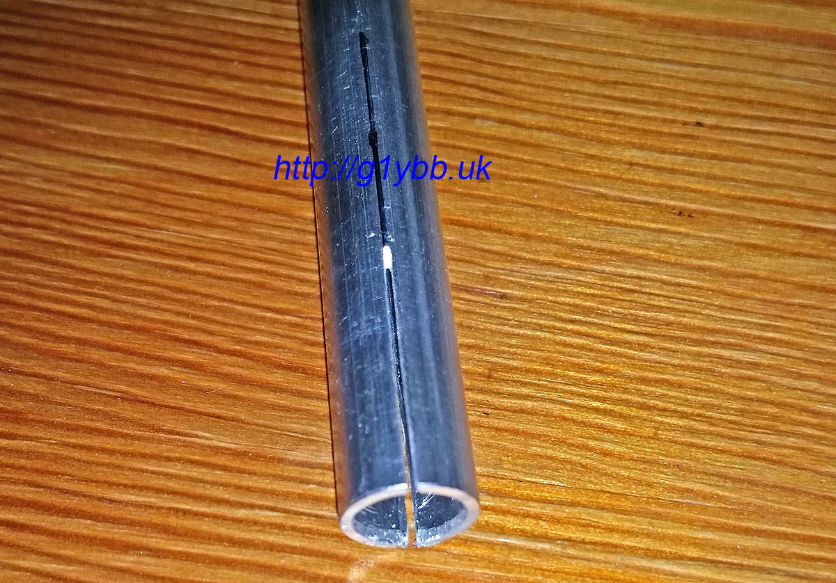
I’m not fantastic with a hacksaw to be honest but using the element clamps above to hold the tube in the vice I was able to cut (from both sides) fairly neat slits with a junior hacksaw (I wanted thin slits):
Then it was a case of fitting the ferrules into the outer halves of the driven elements and adding a screw to maintain a good mechanical and electrical grip:
Next to feed that driven element. I decided to straighten out the feed match to take the feed point a little closer to the centre of the yagi. I’m using WF100 75ohm coax which is fairly low loss for its size, and is not too big or heavy. Its claimed velocity factor is 0.85 so I worked out the length as so:
300/144.300 = 2.079m full wavelength
2079/4 = 519.75mm for quarter wave
519.75 x 0.85 = 442mm
DK7ZB gives a length of 440mm for this velocity factor, but I notice all his lengths are in multiples of 5mm so I wondered if he did some rounding down? I hope so!
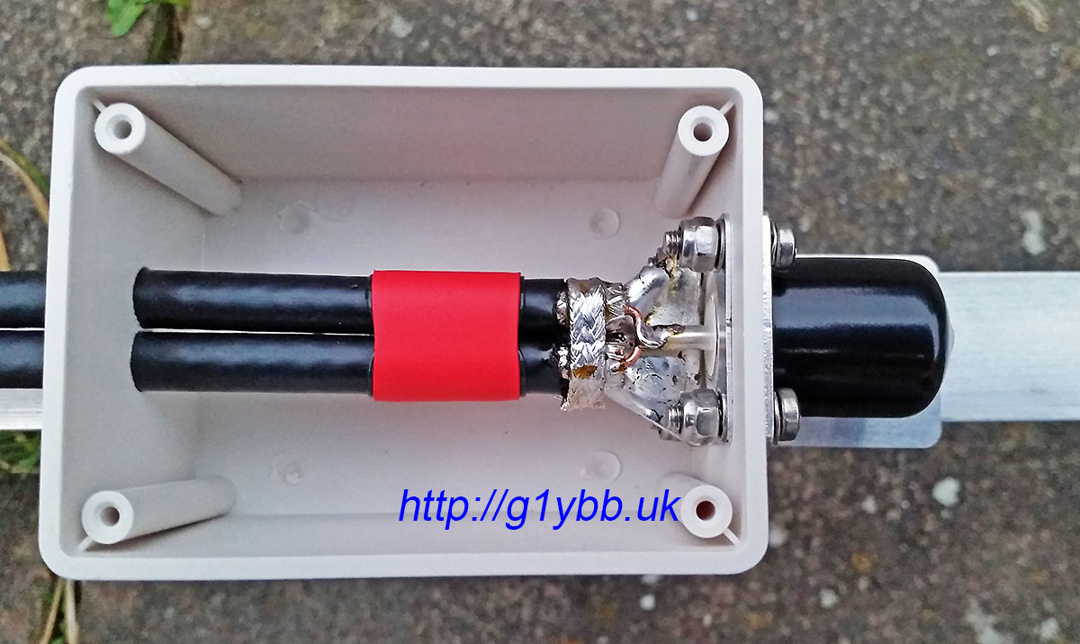
This is the length of the braid. I hate stripping and cabling up coax so did all I could to avoid twisting bits of braid about. I cut the braid and dielectric off square and about 5mm or so of the outer jacket to reveal the braid. With a very large tipped iron of unknown wattage I was able to tin the braid nicely with no apparent melting of the foam dielectric. I then made a small tinned copper plate to bolt to the N-type socket and solder to the braids making a good earth. For good measure I added a loop of braid from some RG223 soldered all round. Then made the inners as short as I could and soldered to the N-type:
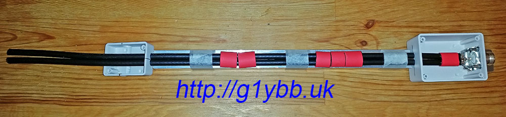
To tame the annoying curling coax I found yet another good use for the short boom offcuts I asked Attila to include. I taped the coax out straight to measure the 442mm finished length:
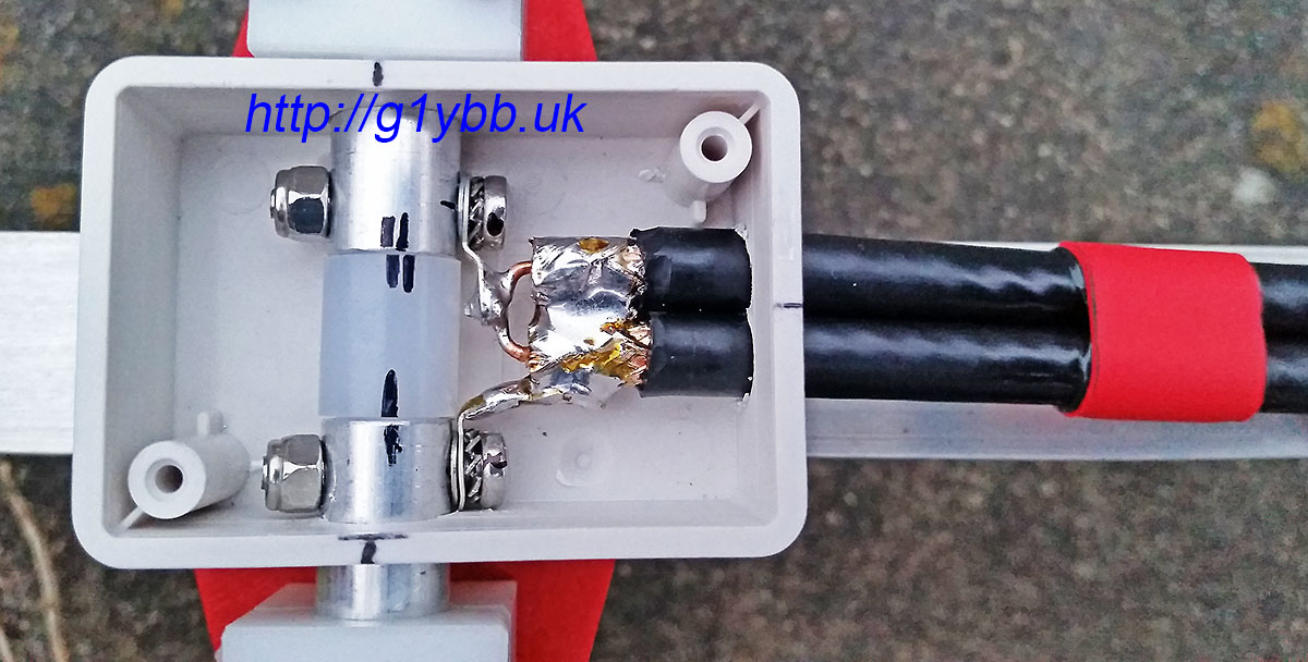
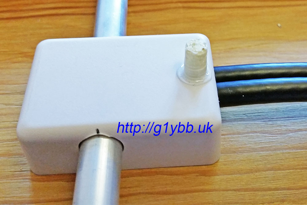
You can see I am using red adhesive lined heatshrink to keep the coaxes tidy and together. In the picture above the tiny box for the driven element connections is threaded on ready for the stripping and fitting of connections. I used a similar method as on the feed end with some copper sheet to join the braids and solder tags to connect to the element halves. This was a very fiddly job but hopefully worth it keeping the connections as short as I could manage:
To support and space the feed off the boom as recommended by DK7ZB (although this is going to be used for QRP almost exclusively) I got some ABS spacers 3D printed which I placed in position and then wrapped tightly with insulation tape. The idea is to keep the coax off the boom (which it is miles away from) but also as far away as possible from the element plate rivets but also as far from the element the coax passes under:
The driven element box is supported solely by the driven element inner pieces themselves, but I added a very small 3D printed pillar to make everything secure:
Here is the feed match finished:
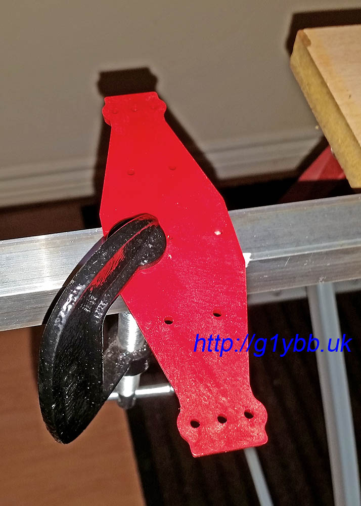
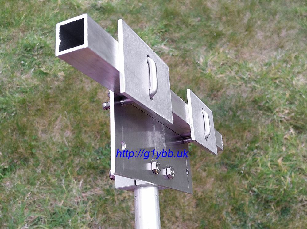
As I plan to use this on a lightweight mast section only 20mm in diameter I didn’t think the usual U-bolt clamps would be able to create enough friction to stop the beam spinning on the mast without being so tight to possibly crush or weaken the 20mm ali mast. I bought some plastic 20mm clamps for large yagi elements from Nuxcom to try but they do not have enough friction. So I drew up some half round clamps to be made out of aluminium:
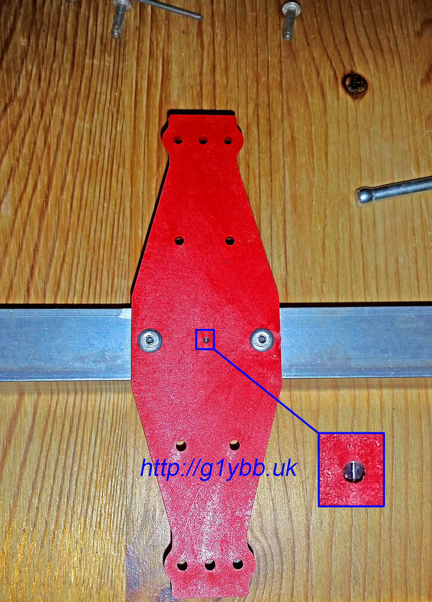
I used a small 3mm aluminium plate in usual manner and bought some 20mm square U-bolts for the 20mm boom itself. As the 20mm boom again is quite small for a long yagi I was again concerned about over tightening the U bolts and creating a weak and potential failure point so I added some small 3mm aluminium plates to allow it to be tightened up nice and tight without any fear of crushing the boom. Here is the finished boom to mast mount. (The two unused holes visible are there to use with the lower 20mm boom mounting holes for a 25mm boom yagi I have):
I used a similar arrangement for the boom support to mast fixings, the aluminium clamps and a slightly smaller aluminium plate. Just a simple M4 bolt per half of the boom support and another plate to help strengthen it all up. The intention is that the boom supports will also help offer a little sideways strength against the wind as well.
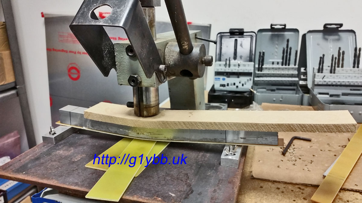
To bend up the boom supports I first tried to bend some 20mm square section (same as the boom) in my workbench jaws (seen above in the first picture after cutting the elements). They were not strong enough to bend it! Note this is not a proper vice as such, more of a drilling and cutting bench with jaws. I then thought I might use a bottle jack to apply the force but couldn’t think of anything solid I could jack onto. Then I remembered we have a small 3000lb lever press at work used for punching small holes in sheet metal. I soon made up a jig using a 10 inch square of ¼” steel with some small aluminium blocks and I used the spare offcuts (yet again) to work out the right amount of packers below the centre to give me the bend angle I needed:
I used 10mm MDF to spread the load from the press and protect the 20mm square tube and a strip of bare FR4 as a bearing and protection to the underside. Once tests were done I quickly and easily put the bends in the actual supports:
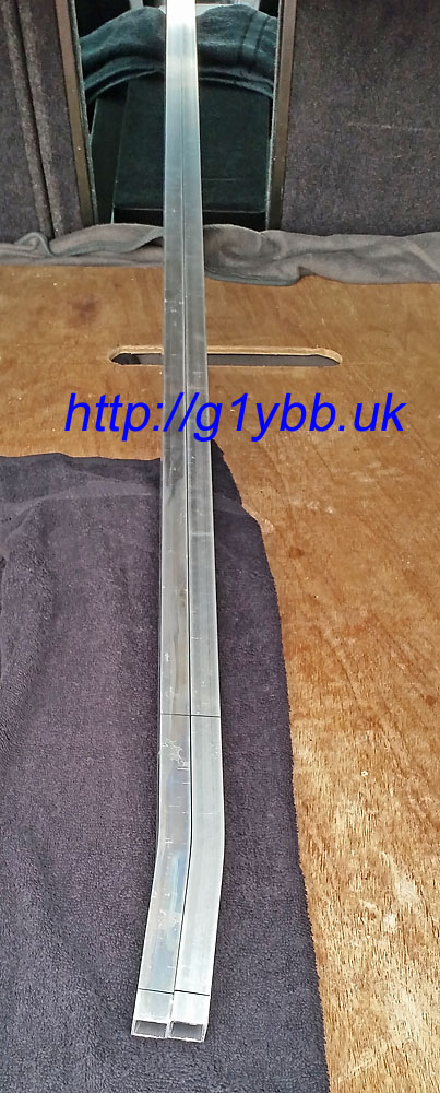
Checking the bends are matched:
Then just a case of offering them up, drilling holes in the right places and fitting. Finished!
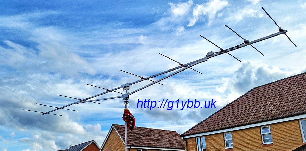
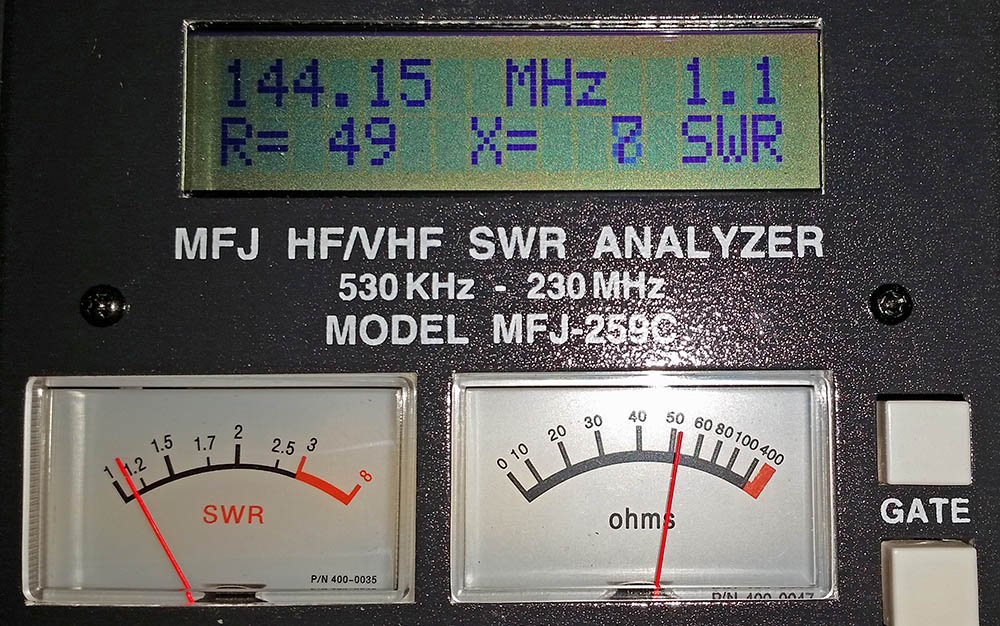
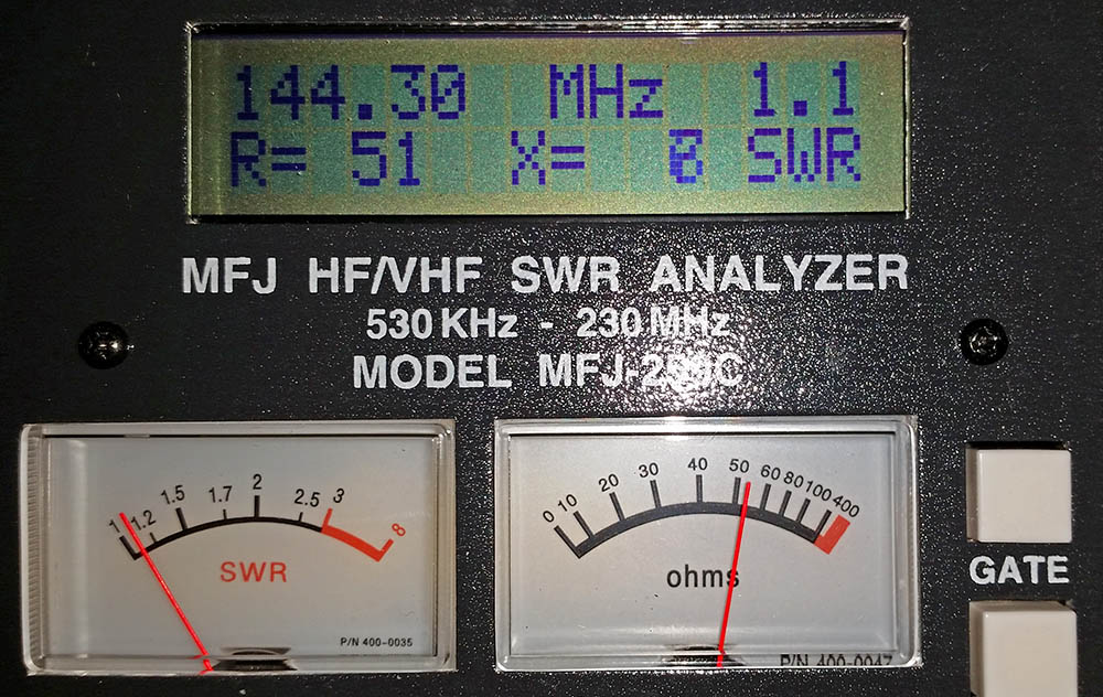
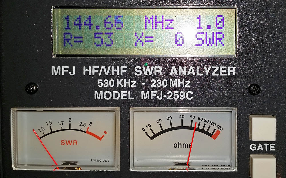
Now for the moment of truth, how does it measure on the antenna analyser? Well to me it looks to be best match at 144.660MHz but is showing SWR of 1.1:1 and 51Ω at 144.300MHz so I’ll take that thanks:
Here is a real time video showing how long it takes to assemble the elements (I have not shown the boom assembly as nothing unusual or new about the boom assembly):
Only job left now is to take this up a mountain top and do some contesting!
Edit: I have done my first contests with this now and it seems to work really well and I got good reports all round. Even with a low loss feeder the radio was not indicating any SWR reading at all on transit. I have come 2nd and 1st in the low power section of the first two UKAC contests I have entered so I am really pleased with the way this yagi performs. It ‘feels’ even as good or better than our 2x 19 element MET yagi array.
 Full results list (PDF)