This was another Covid lockdown project in 2020 to enable me to do some over the air audio checks with locals and maybe give some points away in contests to the locals (my QTH is very poor for VHF/UHF). I wanted something small I could put in the attic. I figured a simple DK7ZB dual band 2m/70cm yagi in the loft with a single feeder would be ideal.
on this page:
https://www.qsl.net/dk7zb/Duoband/4+5_2m-70cm.htm
Martin DK7ZB describes his design for a single feed dual band yagi with 4 elements on 2m and 5 elements on 70cms on a compact 1m long boom.
I already have my element cutting jig (see here) so cutting the elements was easy enough as usual. I went for the 8mm elements to make it nice and light.
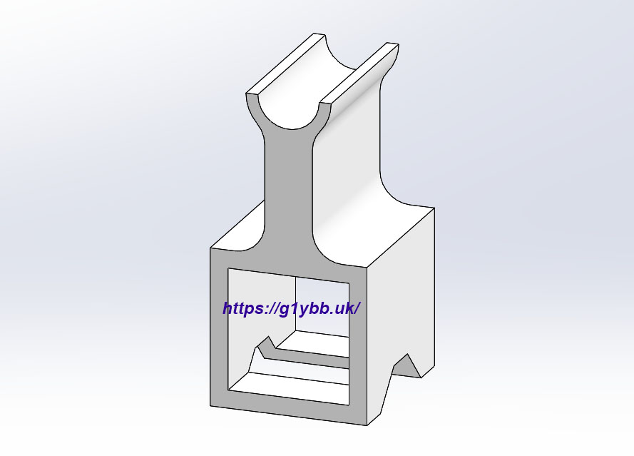
To assemble it I decided I would 3D print not just the dipole box but also the element mounts themselves. The beauty of this over commonly used mounts like the Stauff clamps (see here) is I could design in a feature to ensure the elements are nice and perpendicular to the boom. I also don’t like drilling my tubular elements. For a start it weakens them and also adds a place for inaccuracies to creep in.
So this was my design for the element mount:
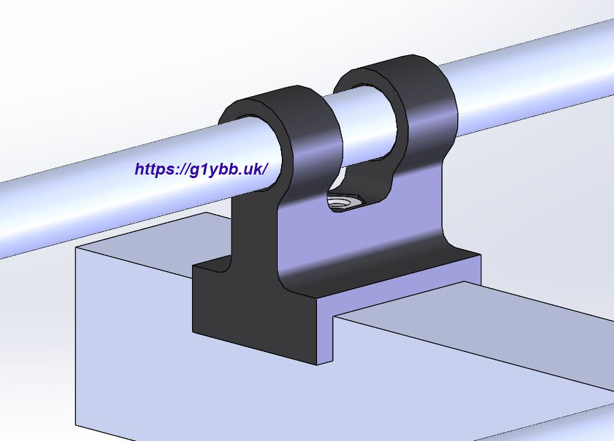
A snug fit onto the 20mm square boom and a friction fit for the elements. It was printed on its side so that the layers of the 3D print went around the element as printing as shown it may break off half of the tube pushing the elements in.
The are secured from below as seen here with an M3 bolt screwing into a captive hex recess in the mount:
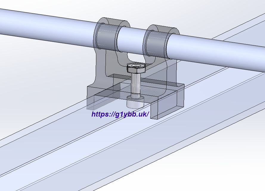
I don’t like droopy dipoles on my yagis so I printed a dipole box to house the 50ohm choke that has integral clamps outside the box and also extra support inside the box:
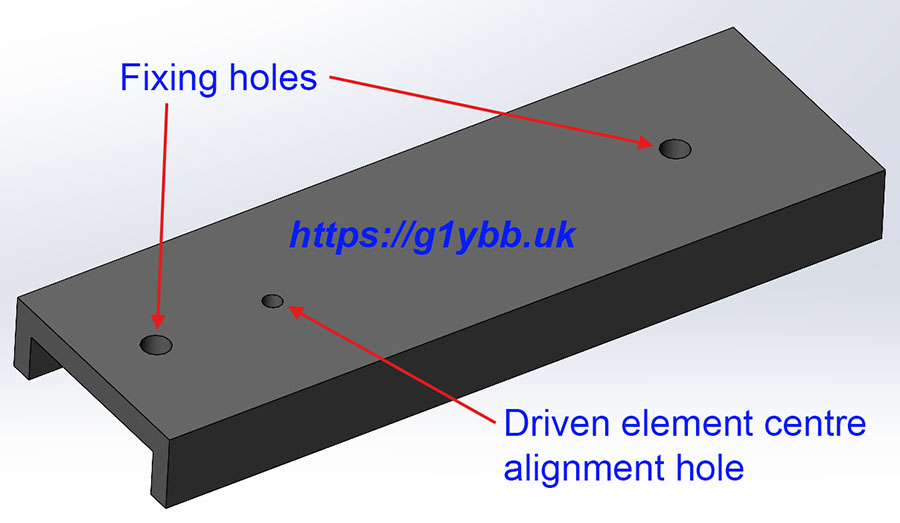
I wanted the dipole box to also align on the boom but did not want to print it with supports as they are messy to clean up after so I used a simple locating spacer with 2 matching fixing holes in the dipole box. The 3rd hole in the spacer is a sighting hole that matches up with the scribed line on the boom for the dipole. This was also used as a drilling jig by aligning the 2mm hole to the scribed line for the driven element position, clamping in place on the boom and drilling through the two 3mm holes.
I used the dipole box spacer/jig to drill all the element fixing holes exactly centre of the boom and on the scribed line and assembly went to plan. I didn’t take photos inside the dipole box on this build but the following image is from a previous build of a 50ohm choke fed DK7ZB design. I hadn’t added the extra internal dipole supports here but I did print the choke former and re-used the design in this build.
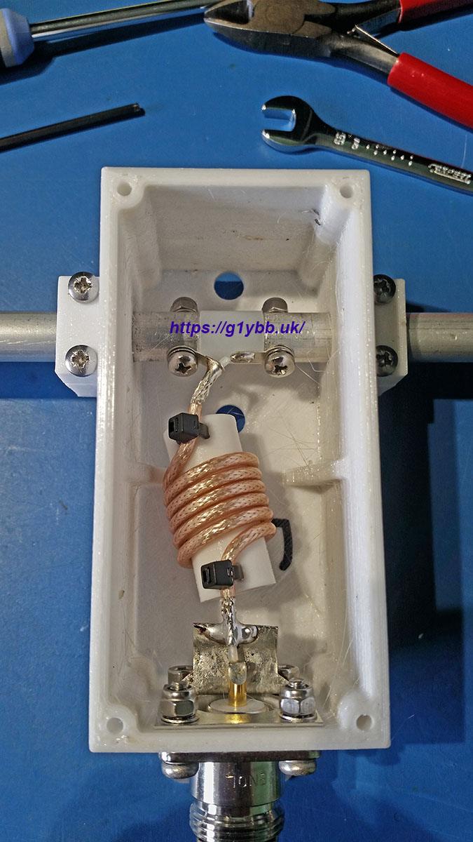
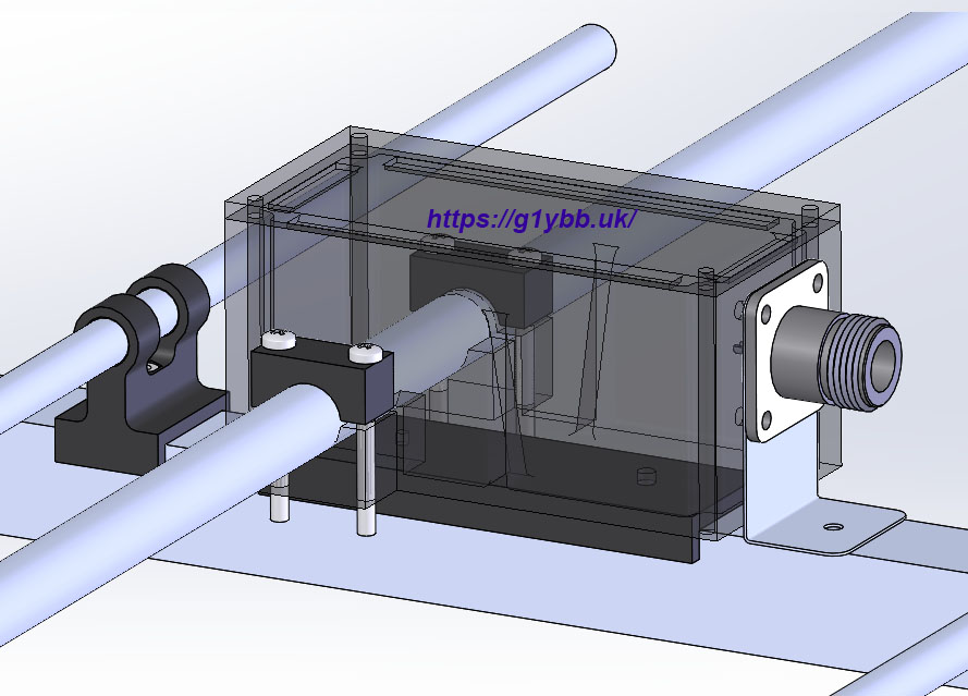
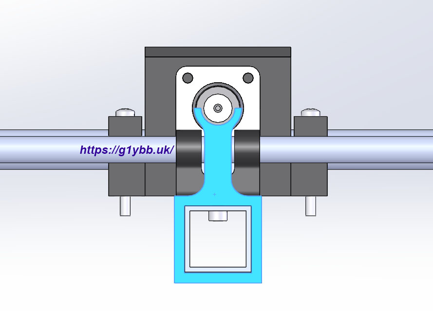
Before final fitting of the elements I added a coax support guide. I usually use LMR400 as my feeder which is great but not super flexible and I like to take strain relief off the dipole box and N socket. This slips over the boom and supports the coax and also helps you align the N plus so you don’t cross thread it:
 Here is an end on view showing the coax support perfectly concentric with the N socket and with a radius to match LMR400. When the feeder is fitted I then use a velcro cable strap, the ones with a slide through buckle you can tighten onto:
 So finally we have the finished dual band yagi ready for testing. The boom to mast clamp is another G1YBB design for maximum flexibility and minimal RF footprint when looking along the boom. The guy ring is also G1YBB designed and seen on this link:
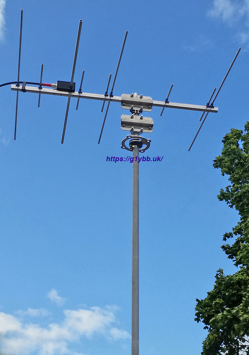
And how does it look on the antenna analyser? I like making antennas and try to make them precisely because I do NOT like fiddling and adjusting much (wire stuff is OK) so my methodology is to try and follow the design with high level of accuracy and hope results match the design.
144MHz SWR plot:

432MHz SWR plot:
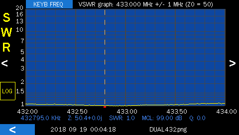
Both are a little high in band especially 2m but the SWR curves are so flat it’s very usable on both. I ended up feeding this yagi in the attic with RG58 as it is easier to route so with the losses in that the radio sees no reflected power as it is mostly used in loss I imagine. However I have made QSOs using this antenna in the loft, fed with RG58 on 23cms using 10W from the IC-9700. I can’t imagine much of that 10W getting to the antenna and what does reach the antenna has to pass through the roof but QSOs have still been made several times.
Edit 2026:
On 26th June (the day AFTER a massive 144 Es event) I did work a few stations on this antenna fixed in the attic at 110°, some SSB and a few FT8, including 2x Ukraine with ODX just under 3000km!
Edit 2 2026:
After some requests I have made the parts available here:
https://www.thingiverse.com/thing:7376853
If you like the results you can always buy me a coffee. 🙂