As we are still on lockdown and my 50MHz yagi is literally too huge to fit in the garden let alone erect on my lockdown lash-up system I decided I needed to make something smaller to use at home. I didn’t have any aluminium tubing at home long enough to make a small yagi so I decided to make a moxon antenna on the recommendation of a friend. These are very compact and easy to make so it seemed like a plan. I decided on a wire based version as although I have some 12mm tube I could cobble together I didn’t have anything I could get today for the corners. Wire it is. I decided easy building of a moxon antenna with 4NEC2 simulations to find the correct starting point would be a cool project.
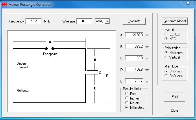
I’d already looked around the web and compared the various online moxon calculators and the AC6LA Moxgen program (link) and the Moxgen program seemed to be the best fit for the suggested spreader angles. (Even though I’m not using spreaders as such.) It’s dead easy, just put your desired frequency in and the wire size and click calculate:
That’s it, job done. Almost…
I’m using normal insulated wire but the calculator doesn’t cater for the change in velocity factor from insulated wire. So I decided to run it through the free 4NEC2 simulation software (link) to make the required adjustments to the dimensions so it would work with minimal fiddling after. I love building, hate fiddling. Now, before you start backing away from the PC this is quite easy to use and just needs some really simple maths to do this. Stick with me. Look at the image above and see I have selected Format NEC on the right. You just do that and click the Generate Model button and save a file ready to open in 4NEC2. Run 4NEC2 and click Open and load the file you just made.
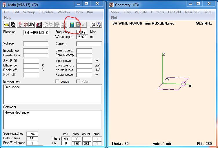
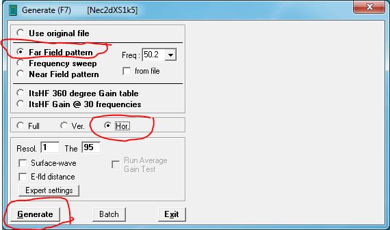
Click that green calculator looking icon to bring up the next screen, choose frequency sweep and check the start and end frequencies are a useful range and that the step size is not too large, then click generate:

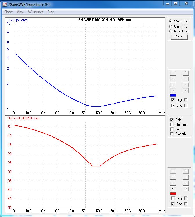
We then get a plot showing us the expected SWR curve of the antenna:
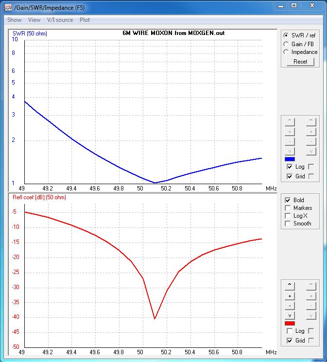
Oddly minimum SWR at 50.1MHz rather than 50.2MHz but looking good. We can click the green calculator button again and this time plot the azimuth plot we are interested in:
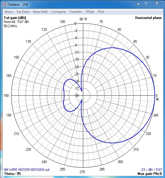
Which results in this plot:
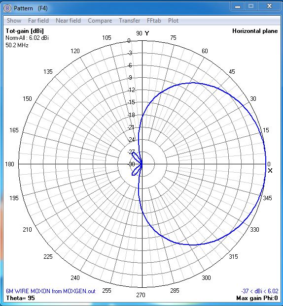
We can see the moxon should have about 6dBi gain and the amazing front to back ratio it is known for. Next to nothing off the back.
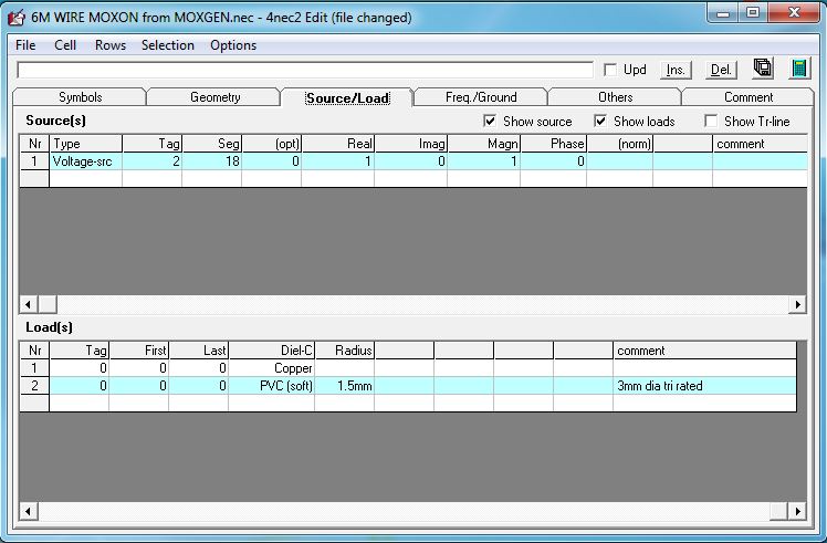
This is all very well but I’m not make it with bare wire so my antenna will not look like this without some tuning. First of all we need to add in the insulation so we can see what the effect will be. On the main screen, to the left of the green calculator is a red book, for editing the information that defines the wires making up the simulated moxon. Select the Source/Load tab, and tick Show loads. We then add two lines selecting as shown below from the offered selections. For Tag, First & Last we put 0 (zero) which will apply the setting to all parts of all wires. My tri-rated wire has insulation 3mm in diameter so I enter the radius, adding the mm to ensure correct scaling is used:
Once done we can click the green calculator on that screen, select frequency sweep again, but widen the scale. I’ve gone 5MHz either side of 50MHz. You can see the resonant frequency has moved 2.5MHz due to the effect of the insulation’s velocity factor:
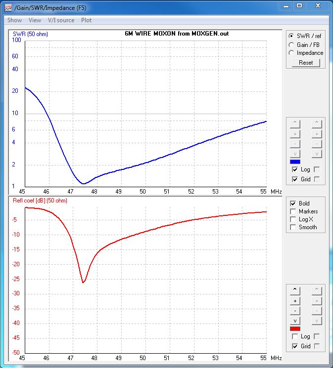
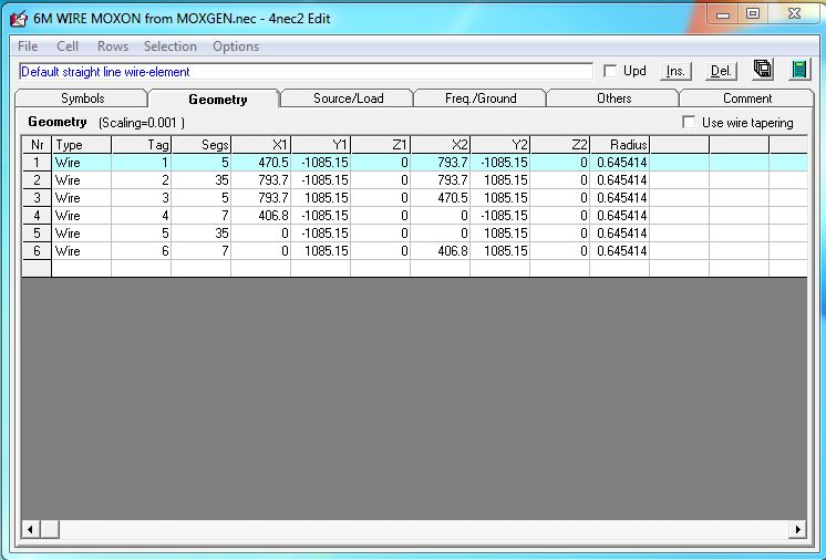
So if we had built to the Moxgen dimensions using my insulated wire we’d be looking at an SWR of about 2.2:1. So we need to make some simple adjustments. The dimensions of the wires are on the Geometry tab below. Looks complicated but it’s just a few repeated co-ordinates. Some with a minus ( – ) sign to make the equal around the center of the axis to plot correctly:
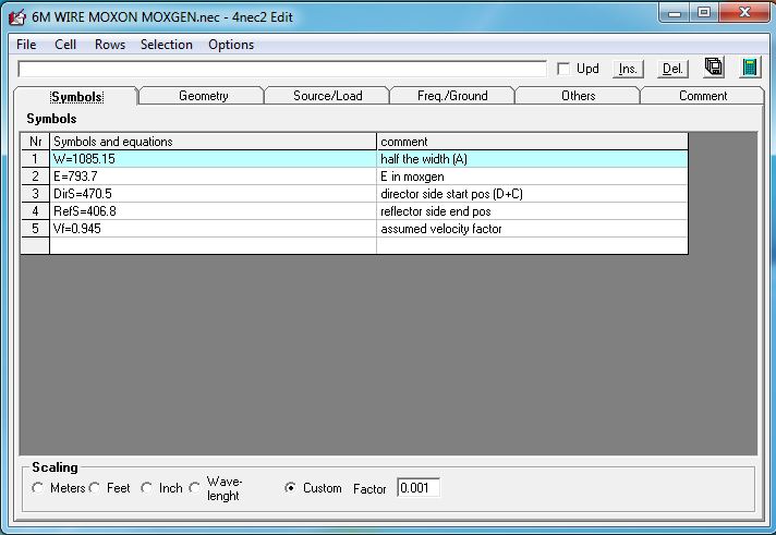
What we are going to do is put those numbers into symbols, or what we would call variables in programming. When you look above there is only actually 4 different numbers used so it’s not complex. You can give them any name you like, even Harold but I have gone similar to the Moxgen image further up. Just click the Symbols tab and enter as shown below. You’ll see a 5th value called Vf. I’ve already tuned it by now but pretend I haven’t:
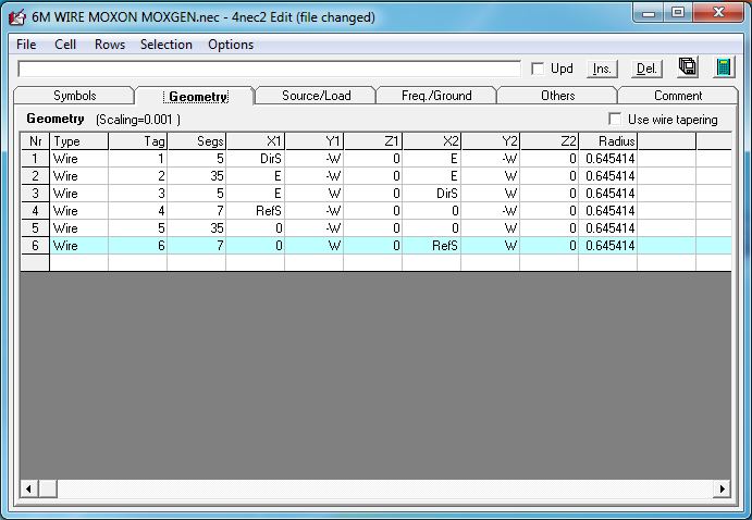
Now we need to flip back to the Geometry tab and put the letters (W, E, DirS, RefS) where the numbers used to be:
If you were to run the SWR plot again now, it should be exactly the same, best SWR on 47.5MHz. But finally we add in the velocity factor. To the end of each of the letter symbols add without spaces
*Vf (star V f):
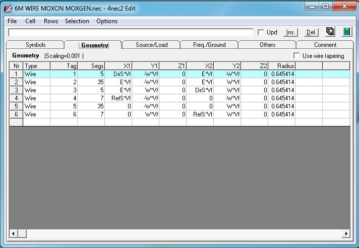
Now we can run the SWR plot and it will apply a Vf correction to every dimension. I found 0.945 by trial and error. They say Vf for wire is between 0.95 and 0.98. I knew mine would be the lower end as it is quite thick. Now if we run the SWR plot, changing back to the 49 to 51MHz range we get this plot:
Back in business. A point to note here. I’m aiming for the SSB section of the band, but if I wanted to cover more of the band I would still aim at the lower frequency with this design. You can see the SWR curves rises steeply on the LF side but gently on the HF side. Anyway, if we run the far field plot we now get this:
As you can see this has changed. A bit less forward gain because we are chucking some out the back now. Now as I mostly do contesting this doesn’t bother me at all but it is interesting nonetheless.
So now we have redesigned the original dimensions to my real world application of actual wire, we should be shooting for success. We just need to apply the scaling factor of 0.945 to the original sizes with a calculator and a little rounding to sensible numbers:
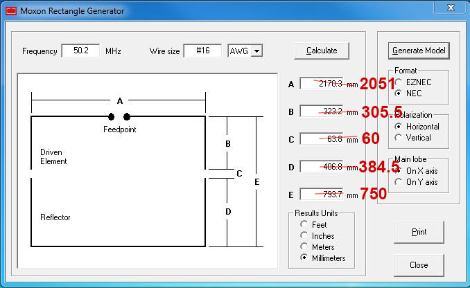
So for the reflector we need a wire 2051+384.5+384.5 – 2820mm long and for the driven element 2 wires 1025.5+305.5 = 1330.5mm long.
Now we can build the antenna and have a good chance of it working!
I decided to make it from a small length of 20mm boom left over from VHF yagis and find some plastic pipes from the DIY shop to support the wires in the A dimension and just stretch them between the pipes for the E direction:
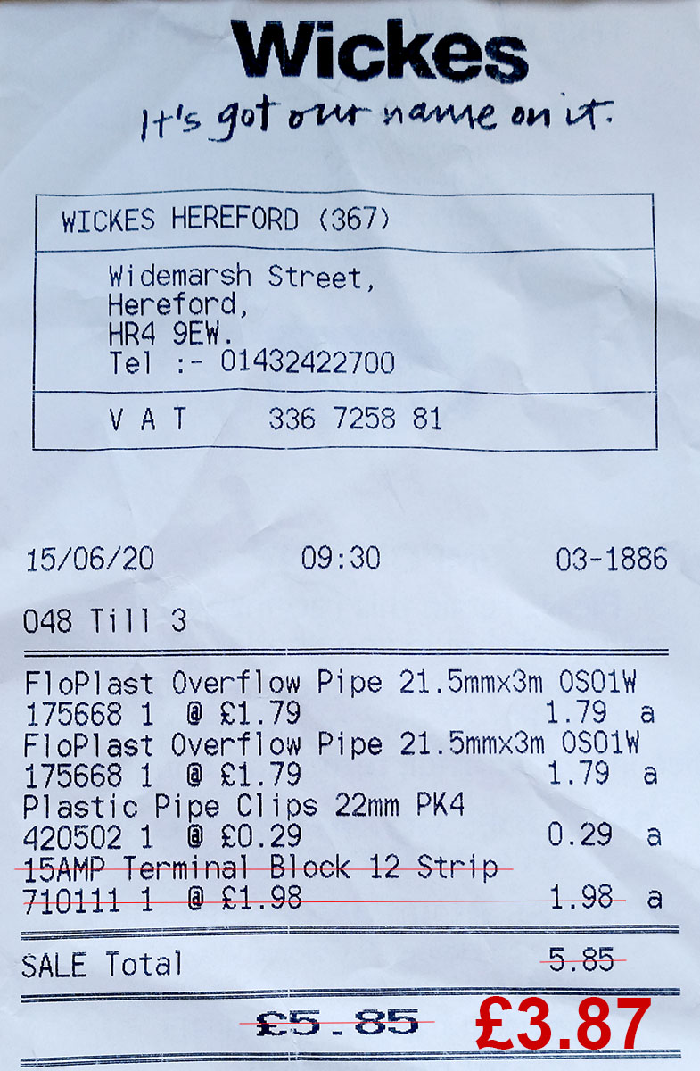
I bought a terminal block strip with the intention of using the brass inserts with nylon rope to join the ends at the C direction but didn’t after so total cost of parts not lying around £3.87. I used my red yagi elemt plates to mount the pipe clips and snapped the pipes into them after cutting to size. They didn’t really grip the pipes so I just taped them on to stop them sliding sideways.
I fitted a short tail of RG223 to an N-type plug, split the other end into braid and core and soldered the two halves of the driven element on and threaded those into a hole drilled in the centre of one pipe. After testing I sealed this with liquid insulation tape:

I had a better idea for the ends of the elements at dimension C. I quickly modeled up a small plastic part like so and sent two to the 3D printer:
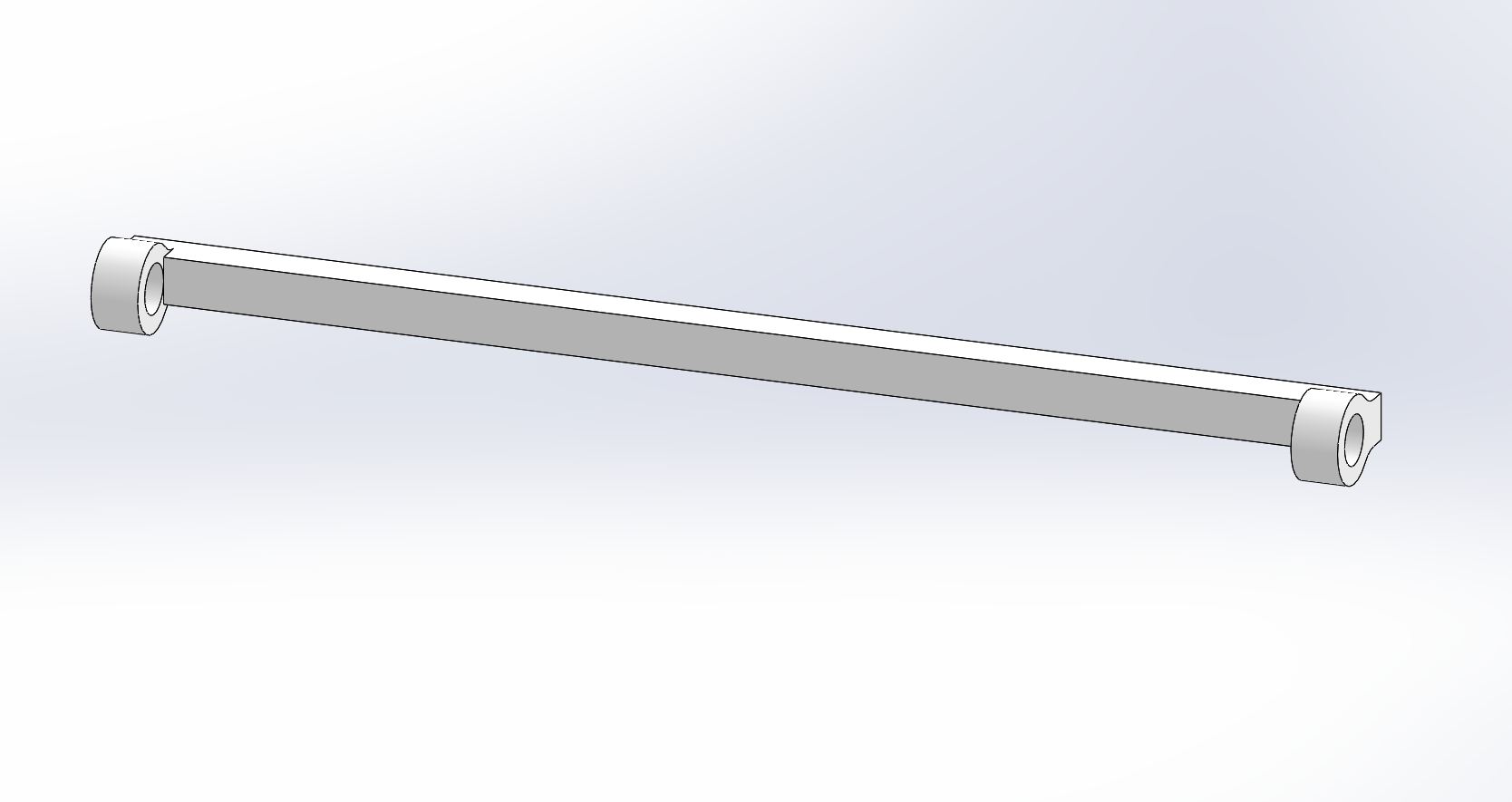 The holes are a snug fit, tight enough to hole the wire until final testing. I marked lines on with a Sharpie 60mm apart and fitted the wires. Once tested I locked off with cable ties:

So, the acid test. What does it measure like?
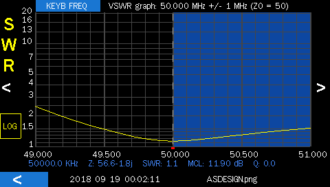
SWR plot is very close but shifted down in frequency. This is because of the plastic pipes which I can’t (or don’t know how to) model in 4NEC2. Not a problem as I expected this and knew that now the wires would be ‘too long’. So I cut 10mm off the end of each element half (4 ends) and ended up with this:
 (just noticed my analyser clock is way out LOL)
Pretty much an exact match to the simulation with 30 seconds of trimming. Just how I like it!
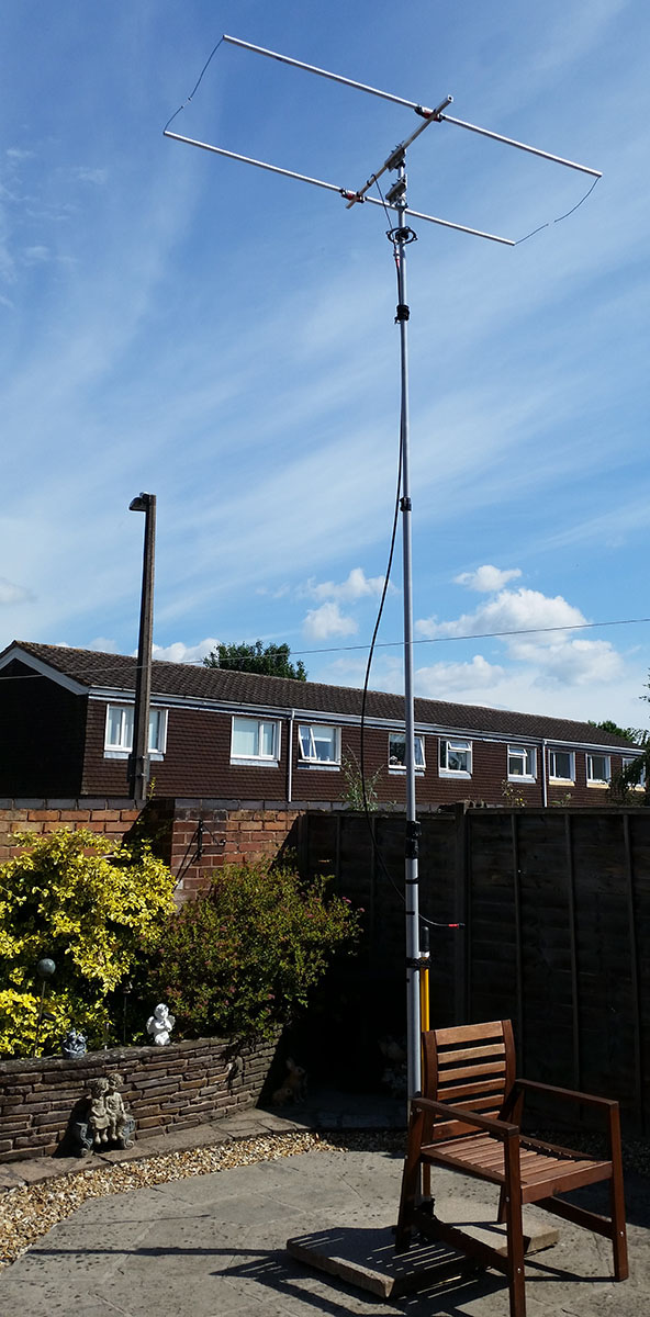
The finished antenna looks like so. It actually looks better than this because this is before cutting the 10mm off each wire end.: