At my location it’s very difficult to have any sign of HF antennas (or any antennas for that matter) up in the garden. I’m already using a covertly erected dipole after dark using this quick erect fishing pole mount. But I was very interested in an ATU free multiband antenna. The hexbeam is nice but too big and needing a rotator. So I looked at the G3TPW Cobwebb antenna. For those unaware this is a 5 band dipole based antenna horizontally polarised and roughly omnidirectional working on 10, 12, 15, 17 and 20m. The folded dipole style with shorting points seemed more complicated than I fancied so I looked at the simpler G3TXQ cobweb design. This filled more boxes for me, single wires nice and easy to tune and a tidy looking feed box. However, it would still stand out in the garden due to it being some strange looking (to non hams) spoked wire thing. What I decided to try was up sweeping the spreaders to make my G1YBB Disguised ultralight Cobweb antenna look like a rotary washing line as there is already one in my garden. I was counting on the neighbours not noticing it had grown an extra arm and got a bit bigger. Except when actually in use I would keep it low down like a normal washing line such as this:

I searched the internet to see what people had designed but no-one had done anything quite this style. I was sure it would work due to the success of the hexbeam, but to be sure I started a thread on qrz.com and got some advice from the man himself, Steve G3TXQ, confirming there should be no reason why it wouldn’t work. Thinking about it the wire positions on this design are quite similar to those on the successful hexbeam.
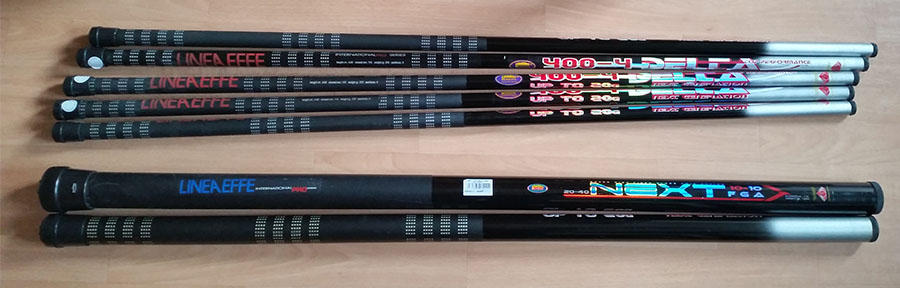
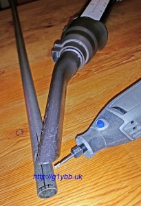
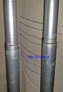
Looking at existing designs all seemed to be based on heavy aluminium plates and tubes to support the spreaders. My plan to use this on a fishing pole would preclude this sort of design. Mine would have to be ultralight to have any chance of working. The spreaders were easy, I would use the 2nd and 3rd sections from telescopic fishing poles like the ones I use for masts. These two sections are long enough (bearing mind the upswept angle means the spreaders need to be slightly longer than for a flat design) and are plenty stiff enough. At the bottom they are approx 20mm diameter tapering to 8mm at the tip. Five 4 metre poles were soon ordered from eBay at a cost of £37.70 with the delivery, making them just over £7.50 each. Here they are next to an 8m and the 10m fishing pole the finished cobweb will be used on:
Next problem was the centre piece which came to be known as the spider. I mentioned what I was looking to do with a non ham engineering friend and it turned out he was about to get a 3D printer on loan. A great answer to my problem, a custom designed 3D printed ABS spider would be perfect. I got straight onto to modelling up the antenna in a 3D design program. This would also allow me to be able to confirm the fishing poles would be long enough and see how it looked, find where the wires should be based on the wire lengths used by G3TXQ and also predict quite well the finished weight. After searching the web a lot for everything to do with the G3TXQ cobweb, many threads on qrz.com with posts from Steve himself, I designed it to have the feedbox in line with the 17m wire, making the 17m wire a square and all the others bunched into the feedbox.
Here is an animation showing how the antenna should look when finished:
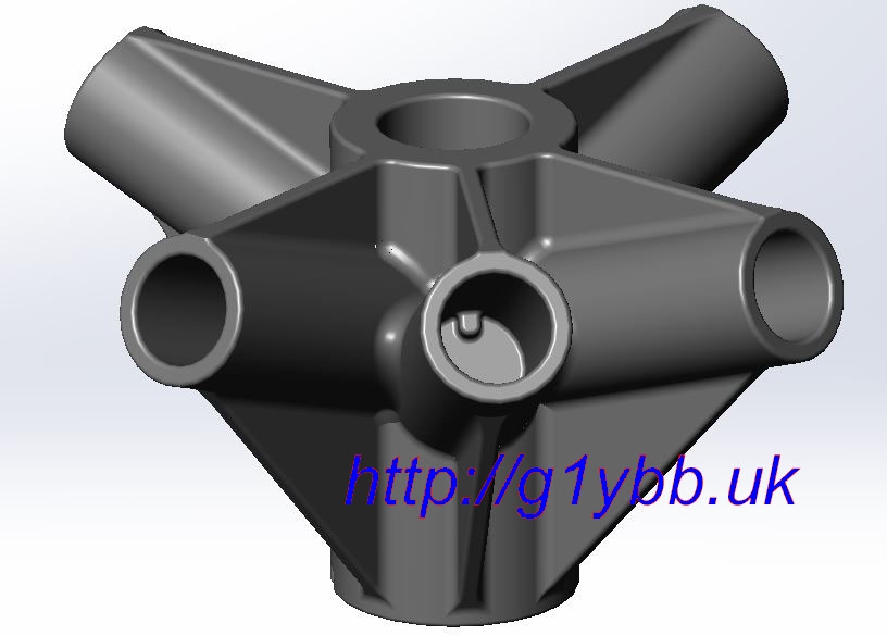
And here is my original design of the spider:
I sent the CAD file over to my friend for 3D printing and the printer reported it would take 95 hours to print! So he decided to strip it down to just the 6 bores (five spokes and bore for the pole) and rebuild it from separate parts that would be glued together after printing. The glue should be stronger than the ABS he assured me.
My design was originally based on the main spider with a slightly tapered bore suitable for the 5th section down on my 10m pole. Not where I planned to use it, but hedging my bets until I got one working and mounted on the pole. I would then use one of 3 sleeves to move the antenna up a section per sleeve. During the redesign we were able to come up with a better idea using end caps and also save a bit of weight, all good.
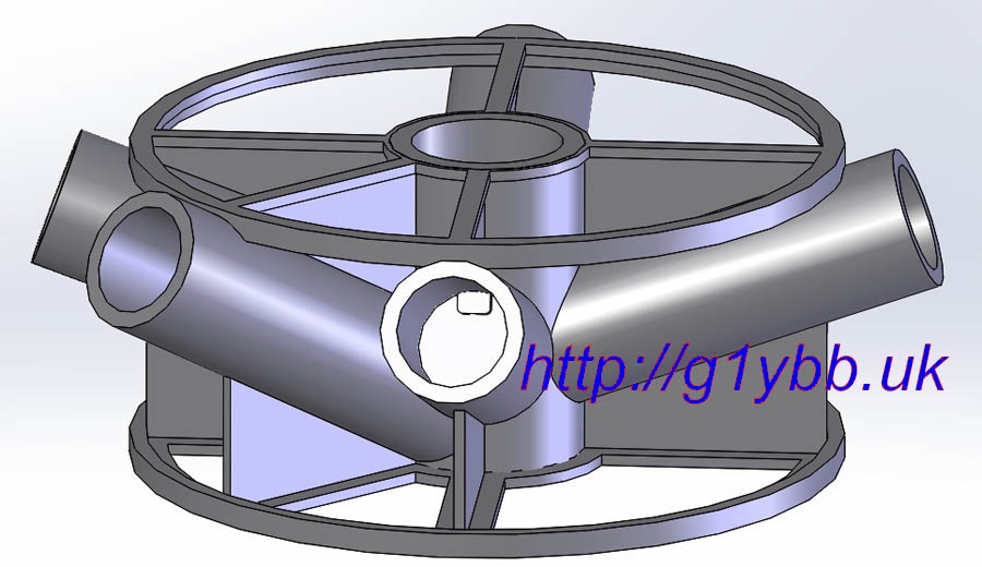
This is the new design:
And on this page the printing process and spider assembly is detailed in more detail.
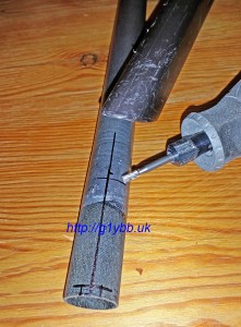
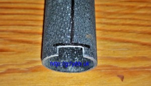
The spreaders slot into the spider bores and need to locate on a pip in the bores to stop any rotation (seen in the spider images above). This is mostly for the feed box to keep it in position but also to securely locate all the spreaders. The ends of the fishing poles are not cut square so I marked a line to indicate the longest part and marked out for the slot to be made with a Dremmel 3000 and a small milling like bit:
To Dremmel the fibreglass safely I set up the hoover as a dust extractor which was very effective:
Finished notch, which is done to all 4 spreaders and the feed box spoke:
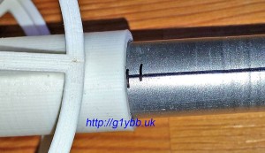
So I knew the notch was deep enough I marked the spreader fitted before the notch is made, then added another mark 3mm up the pole (depth of the pip):
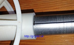
Spreader fitted after notching:
Once this stage was finished I extended each spreader and feed spoke in turn and marked the smaller section at the end of the larger section to indicate how far it fitted, then took them back apart and applied some varnish to the part of the smaller section that makes the joint and extended them again adding a little extra force to ensure they are jammed nicely and hopefully the varnish should ‘glue’ them together. I then added some varnish to the outside of the joint to seal against water running down the joint and inside the spoke pooling in the ferrule. You can see in the picture below that the spreader on the left is going to need another application or two of varnish to seal that gap:
The feed box fits on the feed spoke suspended underneath the feed spoke pole. The angle of the feed spoke bore on the spider is slightly steeper to align the wire entry of the 17m straight in, one nice advantage of 3D CAD design.
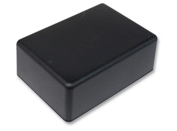
The feed box is an ABS box from Farnell, their part number 244-4686, manufacturers part number TW7-5-11B. Note that Farnell do free delivery to non company accounts now. This size was chosen to be the smallest usable and (hopefully!) fit the feed balun inside:
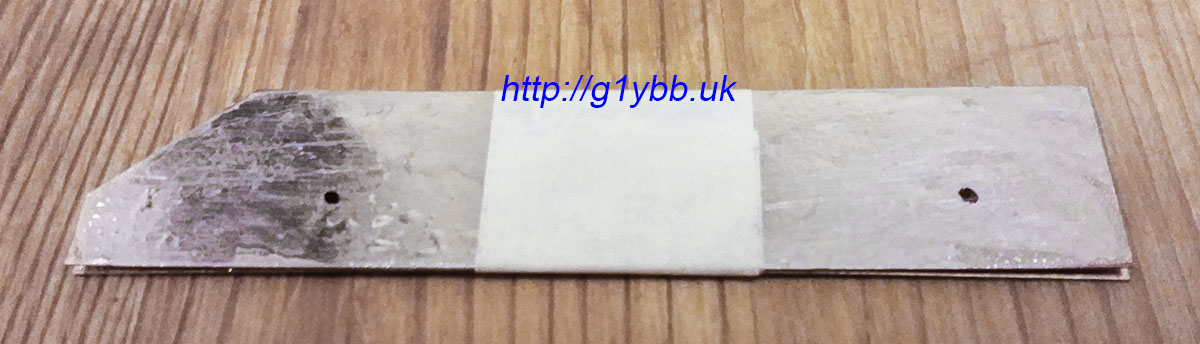
The buses for the wires I wanted also to be lightweight but not compromise on the amount of copper so I abandoned my plan A of some copper clad FR4 when I found some 0.32mm copper sheet. Perfect. That equates to 10 ounce copper where the FR4 copper would have only been about 1 ounce and I have no dead weight in FR4:
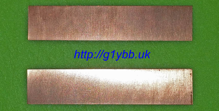
As copper sheet is pesky to solder to I wanted to tin one side before trying to solder even more copper to it in the form of the balun and wires. First attempt with a heavy iron and a hot plate was not very successful. The solder looks awful and you can see the copper discolouration on the bare part before we gave up:
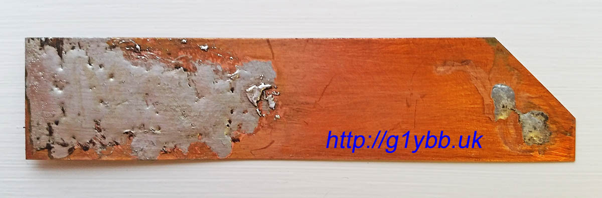
A plan B was required! A multi zone reflow oven and some solder paste was much more successful! Not something everyone has access to but I do so I may as well take advantage of it. The scratches are from scraping off the flux:

To mount the copper flat to the base of the box to maximise space for the balun and simplify the build I needed to Dremmel off the four PCB moulded mounts. For good measure I removed the same mounts from the lid. No point carrying dead weight even if small!

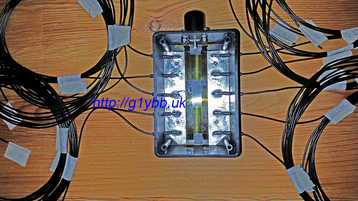
As I like things neat and tidy, I have taped the two copper bus plates back to back to drill a small pair of mounting holes through both together so they match:
Here are the two bus bars fitted with M2x6mm screws:

Instead of nuts and bolts to join the wires on I wanted to minimise weight again so just soldered directly to the copper. Not so good to replace wires but I like to bridge cross problems if and when it’s needed. As I didn’t want to waste space in the box and add extra weight there are no spacers for mounting the copper bus bars. They will sit flat on the bottom of the box. But as I will be soldering with it in situ, especially for the fiddly to fit Guanella current balun, I have added some Kapton tape to the box to hopefully protect it from the heat a little.
The wire I used is 16/0.2mm stranded which measured to be pretty much the same as G3TXQ describes in his text though in his photos the coloured wire looks a little chunkier to me. For the actual lengths I started with the lengths given by G3TXQ here:
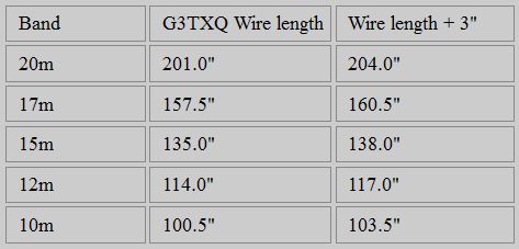
I then referred to his wire thickness adjustments for hex beam wires here:
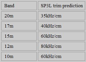
 to see how much things changed for wire diameters then decided that an extra 3 inches each should hopefully be more than enough. I also took note of some predicted and measured figures for the amount the resonant frequency changes when trimming provided by Jacek SP3L in the disguised cobweb thread higher up the page:
 Changing the wires with my construction would be a nightmare so hoped this extra length would be plenty.
Where the wires exit the feed box I’d planned to use Hellerman H20 rubber sleeving but it was too loose a fit to the wire, so instead I used adhesive lined heatshrink which would also prevent water ingress between sleeve and wire.
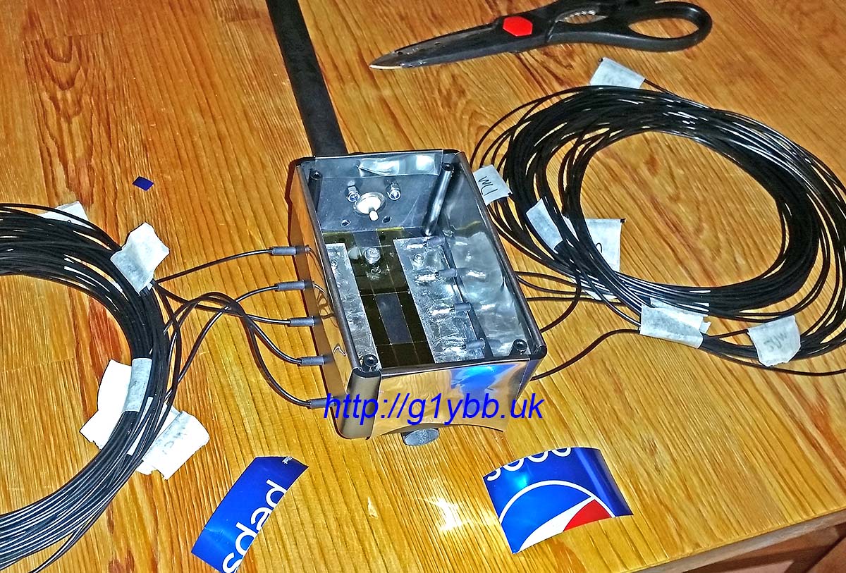
To solder the wires to the copper bus plates I removed them from the box and placed them onto a piece of MDF to prevent heat sinking away. Before doing so I drew around the box and marked the wire entry points so I would be soldering the wire in the right places. The pre-cut to length wires were then threaded into the box treble checking the order before soldering:
Using a 100 watt Weller mains power soldering iron with a 6mm chisel tip I was easily able to solder the wires on with sound looking joints and without melting the previously soldered joints:

Once cool I fed the wires back into the box and fitted the plate and repeated for the other side:
I’m using an N-type socket for the feed input connector as I much prefer them over the SO-239 and PL-259 UHF connectors.
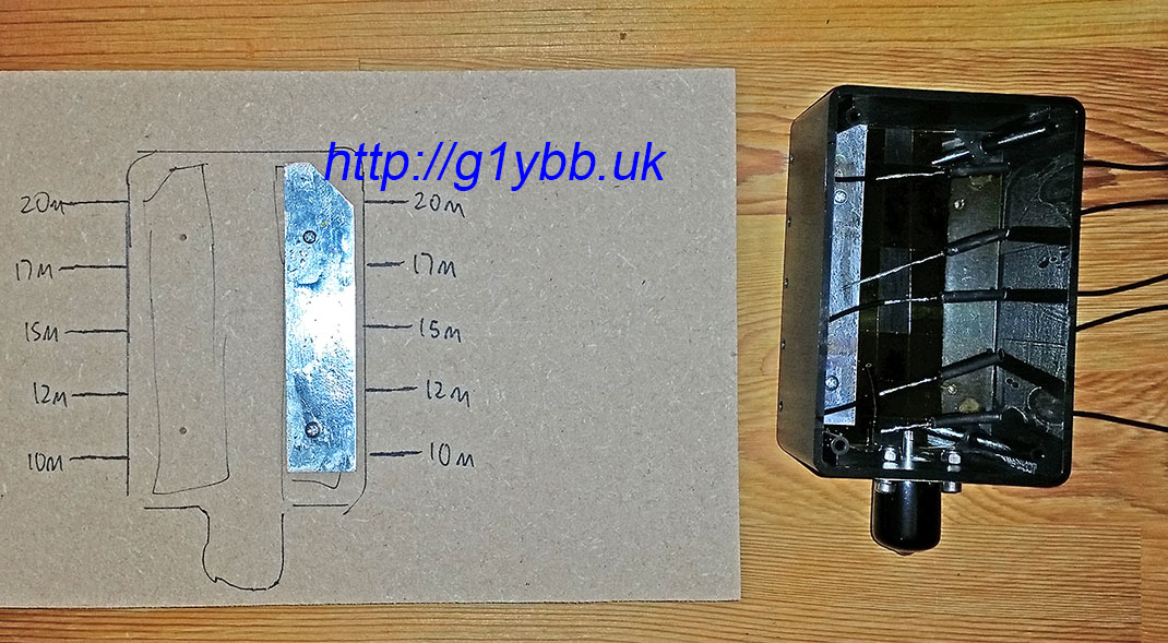
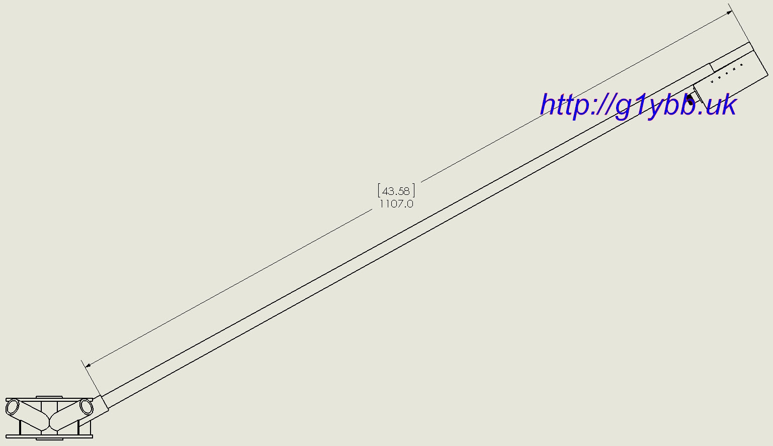
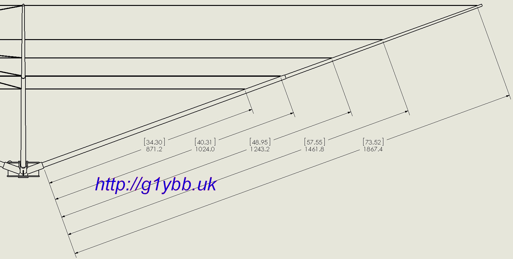
Having created the design in 3D CAD I was able to use my model to tell me how long to cut down the fishing pole for the feed box arm. Using the end of the centre spider tubes as an ideal reference point for a tape measure told me the spot to mark for cutting, in [inches] and mm:
As things worked out the position for the feed box happened to span the joint of the telescopic pole. I had originally planned to use saddle clamps to attach the feed box to the pole, using the same screws for those to hold the bus plates in but I needed two sizes neither of which I could find and to save making them I just bolted the box to the pole with 2x M3 screws and nylocs. I used nylocs so I could tighten up without crushing the fibreglass pole but not have the nuts work loose.
Once the box was fitted to the pole I could then fit the balun. I wanted to fit the feed box to pole first in case once the balun was fitted it was blocking the access to the screws (quite likely). To try and reduce the damage to the edge of the box during soldering (the iron ALWAYS finds a way of melting the box when you are working inside no matter how carefully) I cut up a Pepsi can (other canned drinks are acceptable!) and folded it around the edges, hoping it would make a good heat shield:
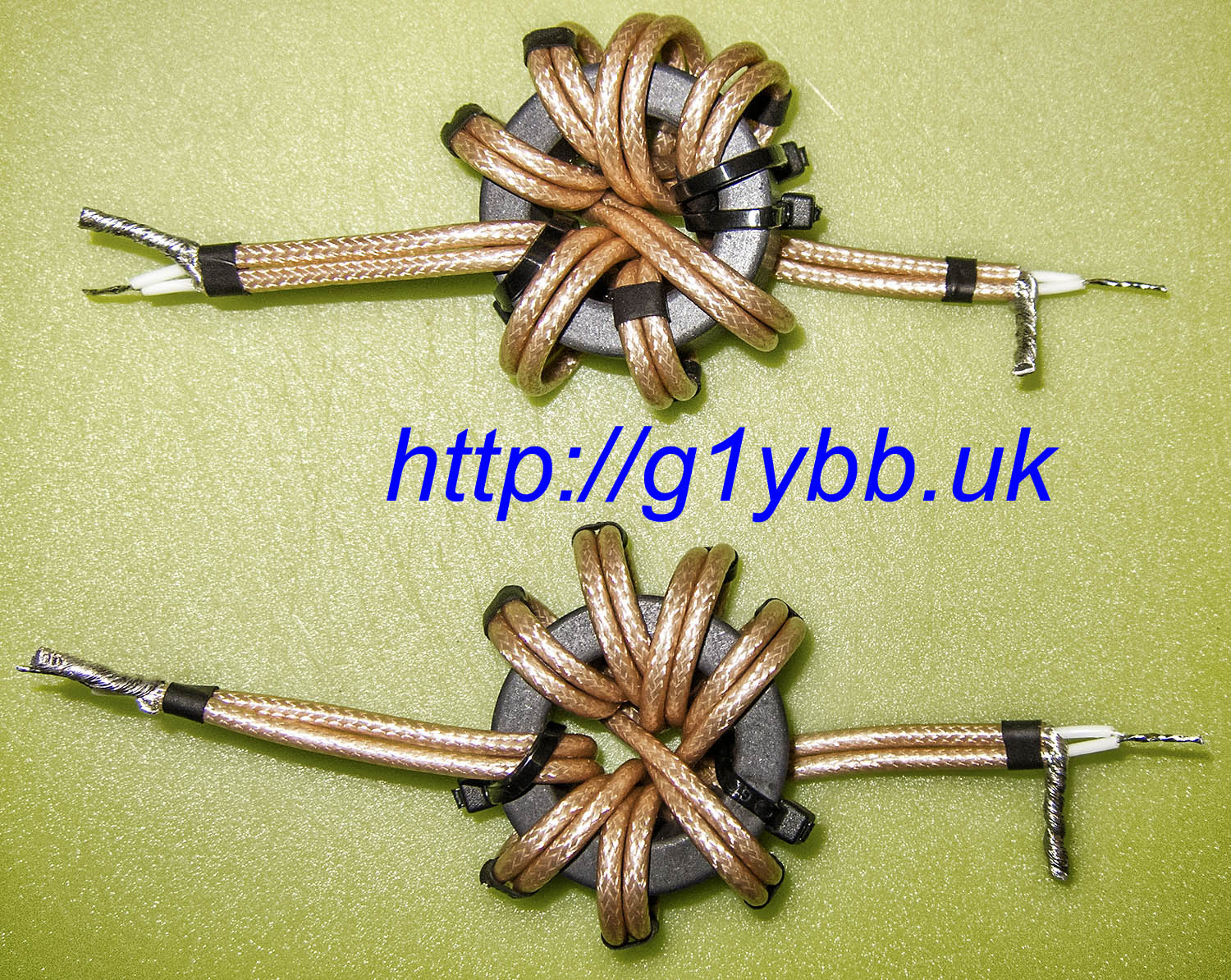
For the feed balun I used the exact same FT 140-61 ferrite toroids as G3TXQ and RD316 (which is just RG316 with a double screen)
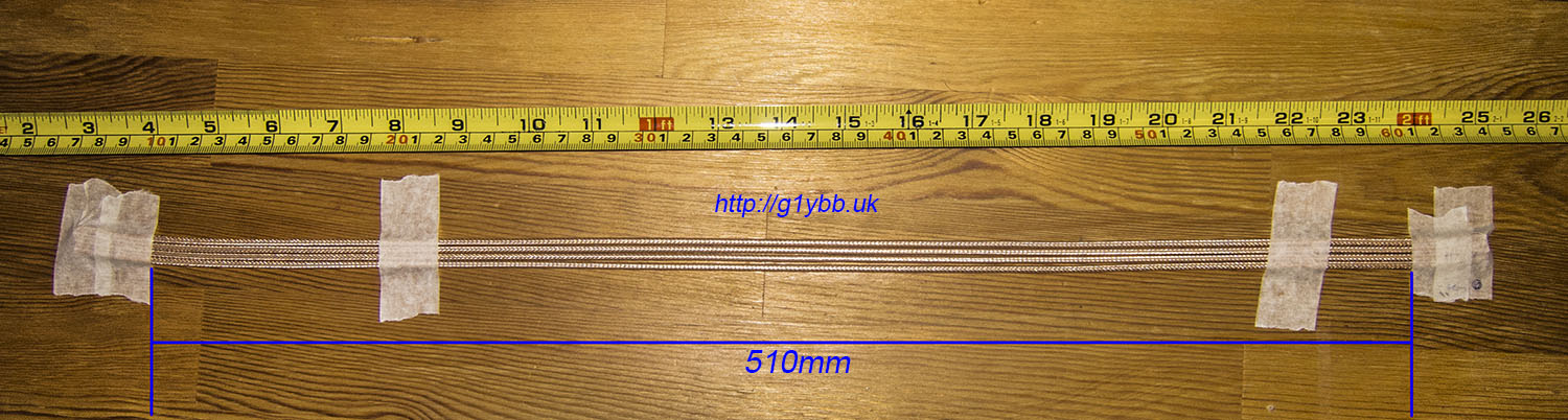
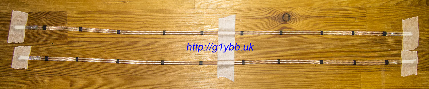
4 lengths of RD316 taped out for marking exactly the same lengths. Apparently the outer jacket of RD316 is repellent to all marker pens including biro, Steadler permanent markers and sharpies. So I marked the line to strip the braid off with masking tape then slit down between each piece to leave a strip on a marker:
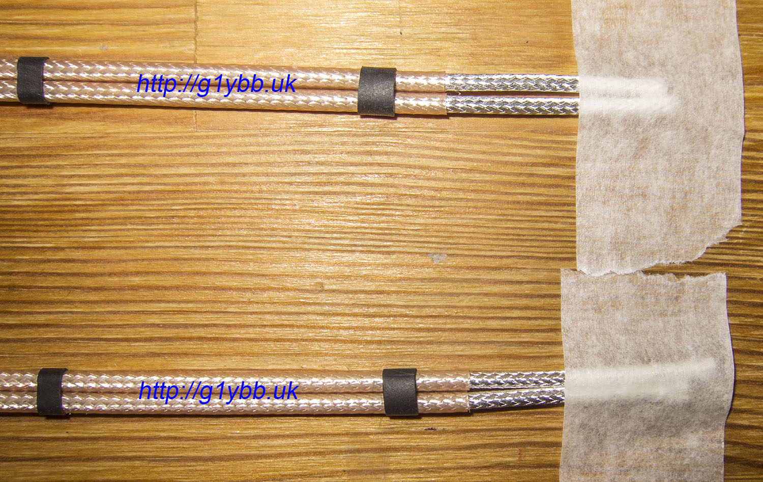
Outer jacket removed and bits of heatshrink added to keep the 2 coaxes together. This also helps stop the coax curling up all the time:
Close up showing quite closely matching outer jacket length remaining:
Both 1:1 chokes wound:
To fit the balun into the feed box I first loosened the four screw holding the two bus plates in so I could slip some thin card (from a cereal bar packet) under the ends of the bus plate where I would solder the coax (paralleled end) then soldered the coax to each plate. Then I removed the card and tightened the screws back up on the bus plates and added a drop of varnish to each one. I then fitted the other end (the series part of the balun). This job didn’t turn out to be as much of a stressful procedure as I expected. The heat shields worked perfectly and the box survived without any damage! I used some Hellerman rubber sleeves where the wires exited the feed box

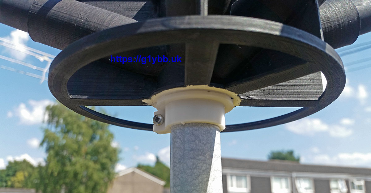
As this project has taken me so long because I started make VHF & UHF yagis for contesting and doing lots of contesting, in that period I have moved away from using the fishing pole as I now have a more heavy duty pole this can go on. I did test mount it on the fishing pole and it is still viable. But it fits even better onto my 23mm diameter 3mm wall mast top section. To do this I designed and 3D printed adapter washers and simple locking collars to fit top and bottom. In the first photo you can see that without my glasses on I have fitted the collar upside down as the ridge is supposed to mate with the groove.

The wires are fitted to the spreaders with some 3D printed guides I drew up and printed. The wires pass through holes so the spreaders should self centre and tension be equalised all along the wire.

As my design is closely following the build of Steve G3TXQ I was able to use 3D CAD to determine where the wires should be attached to my spreaders if all goes to plan and at the very least give me a good start point. This could of course change if my wire turns out to be thinner or have a different velocity factor from the wire Steve used. These are the positions using the same wire lengths as on Steve’s page:
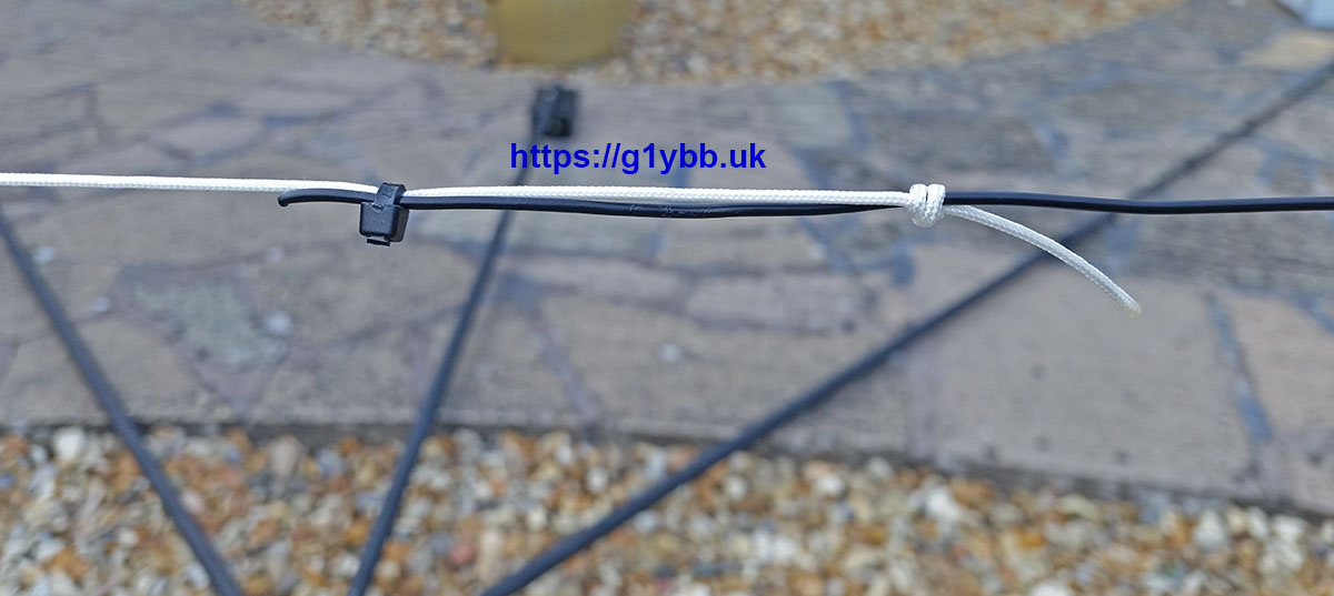
To join the ends of the dipole I used nylon cord as used on bathroom light pulls only a bit thinner, thin, strong and light. I used a tight fisherman’s knot in the cord to grip the wire and taped the string to the wire ends to keep the wires straight at the ends whilst tuning then locked off once tuned with a cable tie as well.
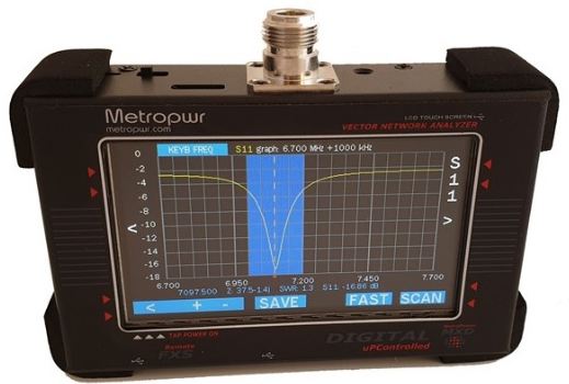
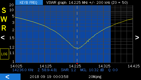
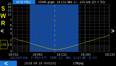
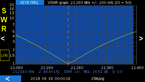
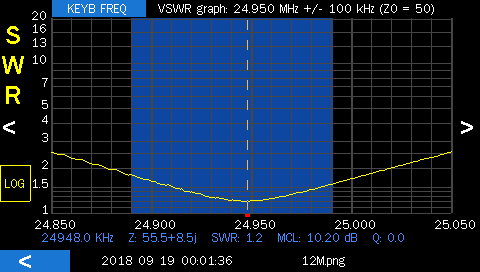
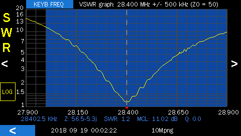
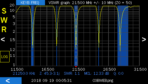
Tuning I did with the extremely useful MetroPWR FX700 antenna analyser, taking notes of how much I cut off each time affected the resonant frequency. I decided my target tune frequencies would be somewhere near midway between the SSB and data portions as from home data modes is very family friendly with no shouting to annoy anyone.
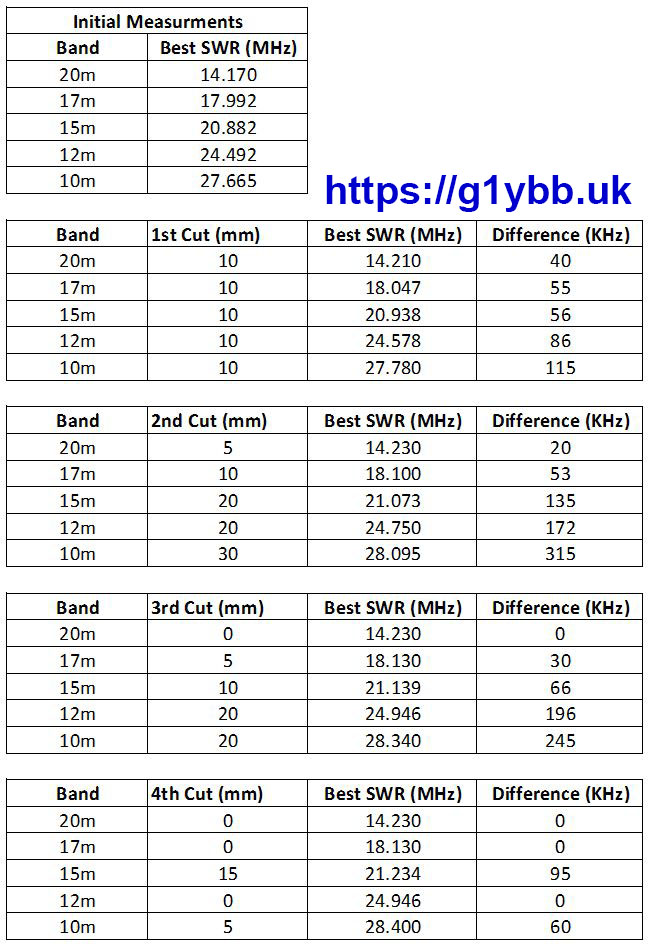
SWR results are as follows, measured at about 30 feet above ground.
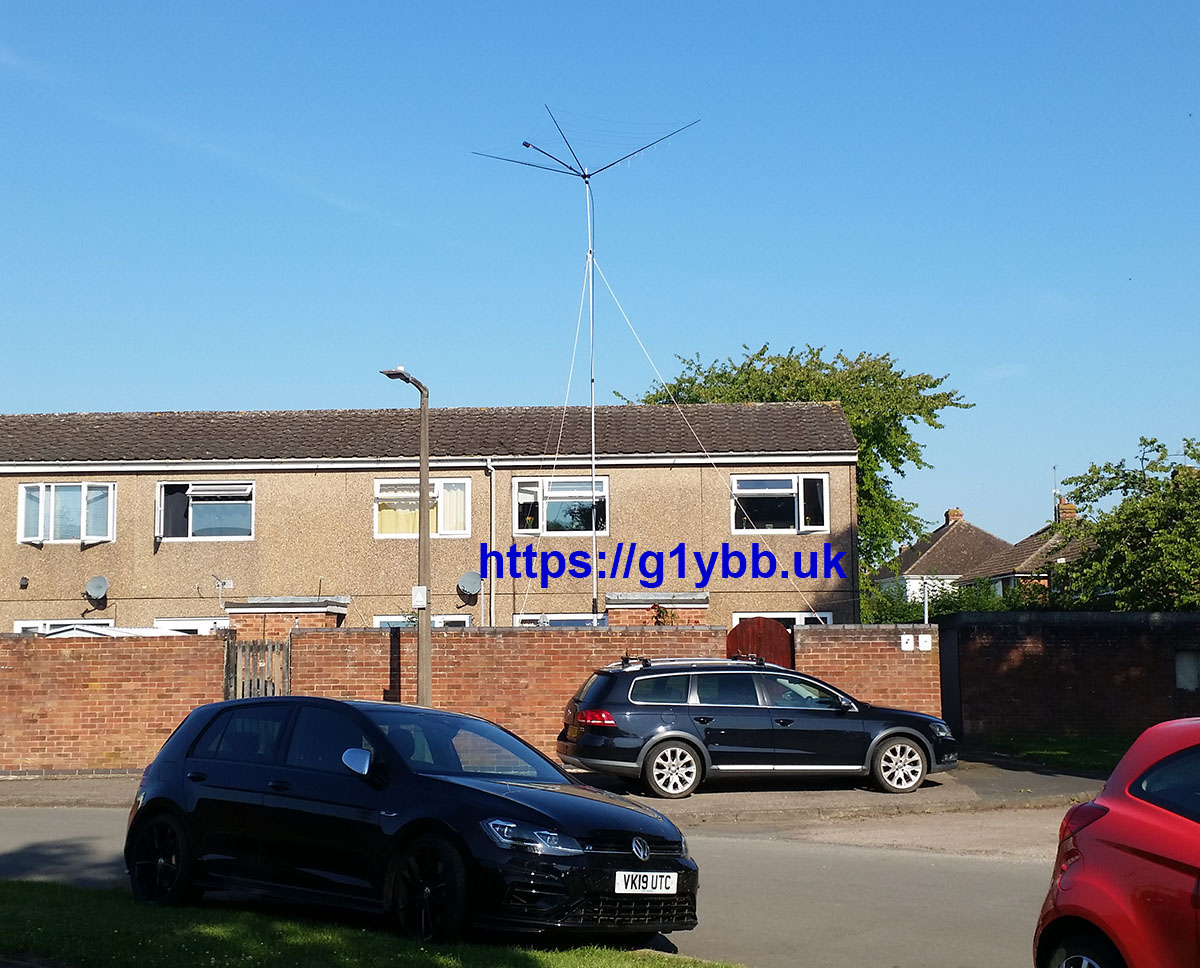
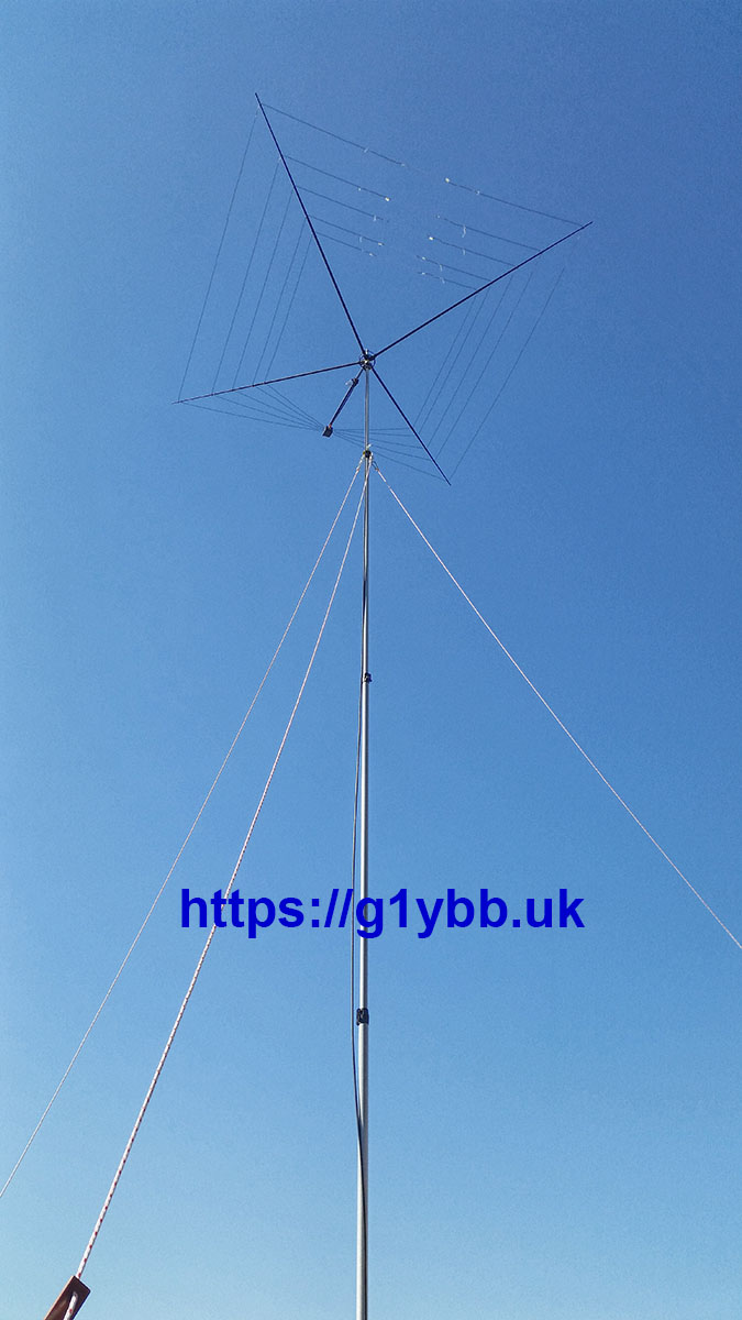
Finished antenna pretending to be a washing line. It sure looks like one but I don’t think I quite have the disguise cracked…
As this started off to be an ultralight cobweb it’s worth stating the weight. Weighing myself alone and with the cobweb complete on the bathroom scales it comes out as 1.2kg overall.
Final Note:
It is with sadness that this took me so long to complete, and during that time Steve G3TXQ succumbed to illness and is now SK. Steve had some thoughts on the antenna that we exchanged, both via email and in this QRZ thread. It’s a great shame for me he never got to see the finished antenna he inspired. However the QRZ thread did stimulate some good experimentation on cobwebs and is well worth a read through for that alone.