You may wonder what a mini lathe cross slide modification has to do with Amateur Radio but it is a tool I use a lot for radio gear. Mostly for the plastic bearing rings on my coax loop free guy rings ( https://g1ybb.uk/g1ybb-coax-loop-free-guy-rings/ ) but also for other little items like the YBB Washer ( https://g1ybb.uk/the-ybb-washer/ ) so very closely related to my radio activities.
My lathe is a cheap Warco mini lathe that I bought from an old friend G3LZM (now SK) and it sat unused for a LONG time. But now it sees more action and as a good friend of mine recently bought the Warco super mini lathe and has corrected some of the cost saving shortcuts I am trailing along adding a few to mine. So this one deals with the cross slide, or to be precise, the lead screw.
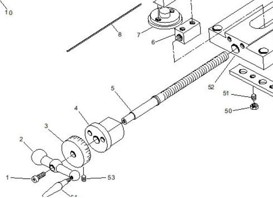
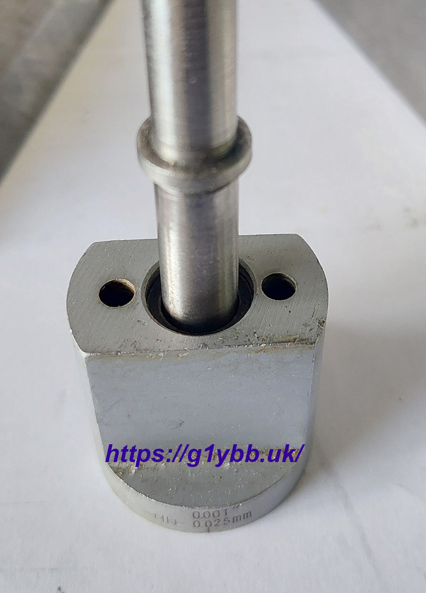
As seen in the exploded view above the lead screw (item 5) has a shoulder on it that sits in a machined recess in the cross slide boss (item 4) and it trapped up against the main body of the carriage (item 52). There is no bearing at all and the boss is aluminium. You can see this in my photo below:
So my friend decided to solve this by adding a thrust washer either side.
These are the thrust washers:
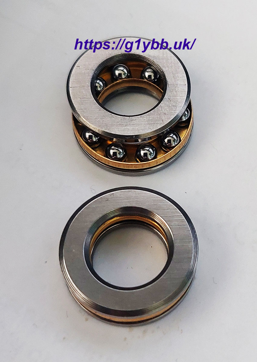
These are too large in outer diameter to be used with the original boss as the two M4 fixing holes are too close together. So a new boss is required. My friend made a 3D printed test piece then machined a new aluminium one but I am just going to print one from PETG which is more than strong enough for this application.
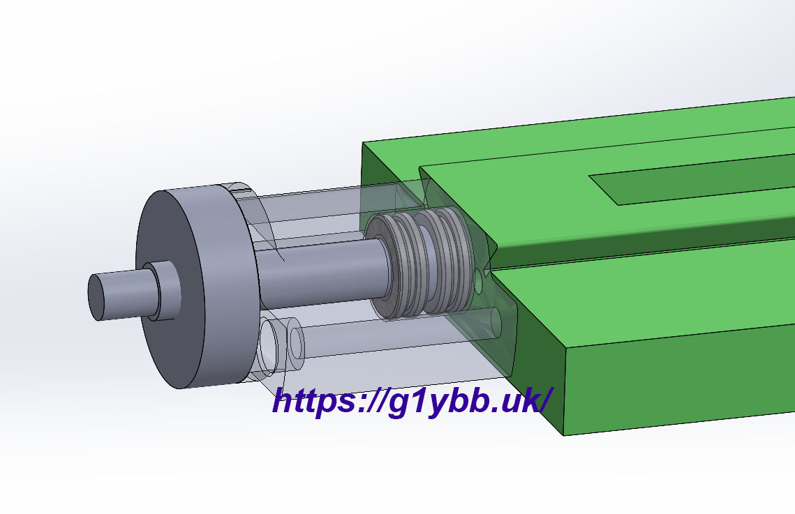
My friend sent me the 3D model he did and I tweaked it to suit my intent and lathe. Here you can see the 3D printed boss as transparent and the 2 thrust washers either side of the lead screw shoulder in a larger recess in the boss:
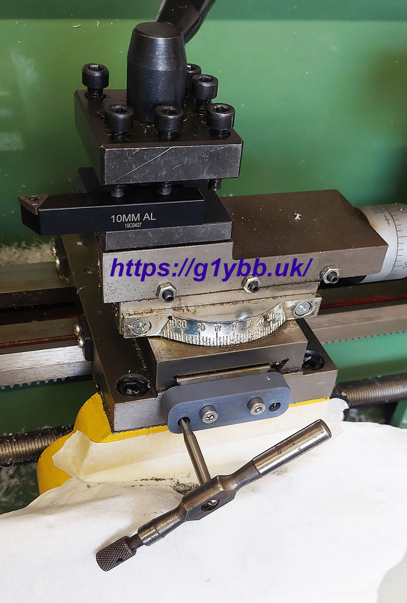
 To fit this I needed to drill and tap two new fixing holes in the carriage. I didn’t want to take it all apart to drill so decided to drill in place. But it’s really hard (for me!) to hold a drill (and then a tap) square. So the 3D printer said “Hold my beer, I got this for you”
I drew up drill jigs. These have a boss that goes in the lead screw hole in the carriage with a close fit and two 4.0mm holes for the existing fixings. The two 2.0mm holes for the pilot drill. I made a 2nd jig with 3.0mm holes for the next size up drill in case the first one was worn making the initial hole. These were in PETG and actually showed next to zero wear.

Here is a test fit of the drill jig (excuse dodgy throat-bad cold):
And here in use:
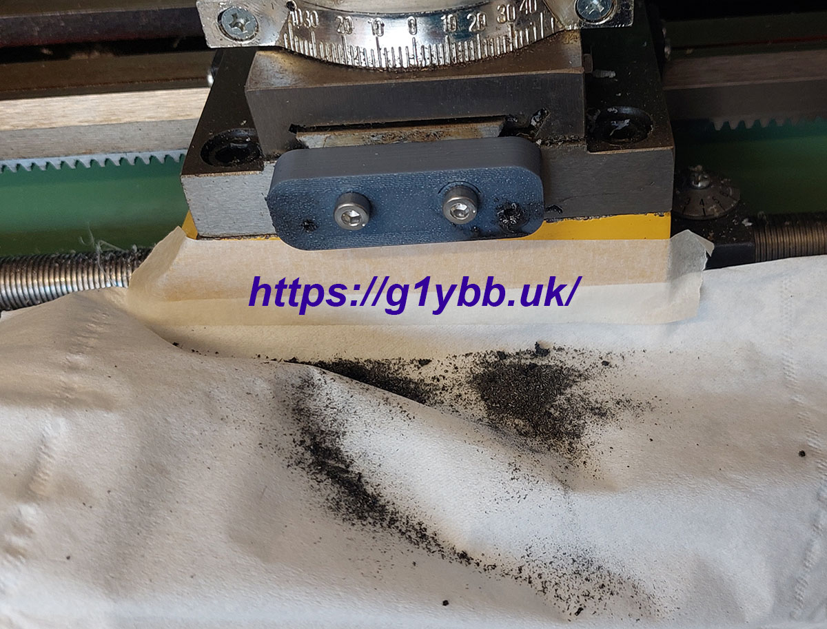
I decided to use it to guide the tap in straight as well which worked very well.
I was then able to do the test fitting. There were a couple of issues. The pocket for the thrust bearing was a little too shallow so when the boss was tightened to the carriage they were under pressure and not running freely. The bore in the boss was a little snug on the lead screw shaft but the one thing that made it scrap was the boss was a bit too long for the graduations wheel. I didn’t have it with me at the computer (doh!) so I needed a tweak:
Back home and after a few minutes in Solidworks and an hour or so on the (new faster Bambu Lab P1S) printer and a new version is ready:
Back to the lathe and install it and seems to work a treat. I literally can’t detect any backlash at all really, surprisingly. That’ll do for me!
Apologies for my dodgy throat again in this one from a bad cold. A point of note is the graduation dial is now in mm as the lead screw is metric yet the lathe comes supplied with a dial in thou.