As an avid antenna constructor myself this is a bit of an unusual post for me. It comes around as I was planning to build myself a dual 10m and 6m beam based on the DK7ZB design on this page (link). I was already running late as the Es season was well underway and in chatting with the Hereford club members Clive G8LNR said there was a tri band version of the same thing doing nothing I could borrow. It was made by VPA Systems and sold by TelTad on this page (link). This was ideal for me as it would save quite a lot of time, so I leapt at the chance and fetched it to my house to build.
This is a lightweight budget end of the market antenna with a claimed weight of 3kg and costing 193€ but that is ideal for my purposes. I retract my mast to gutter height when not in use and I don’t want heavy antennas on the aluminium mast (I’d love the Optibeam OB6-3M but it’s just too heavy).
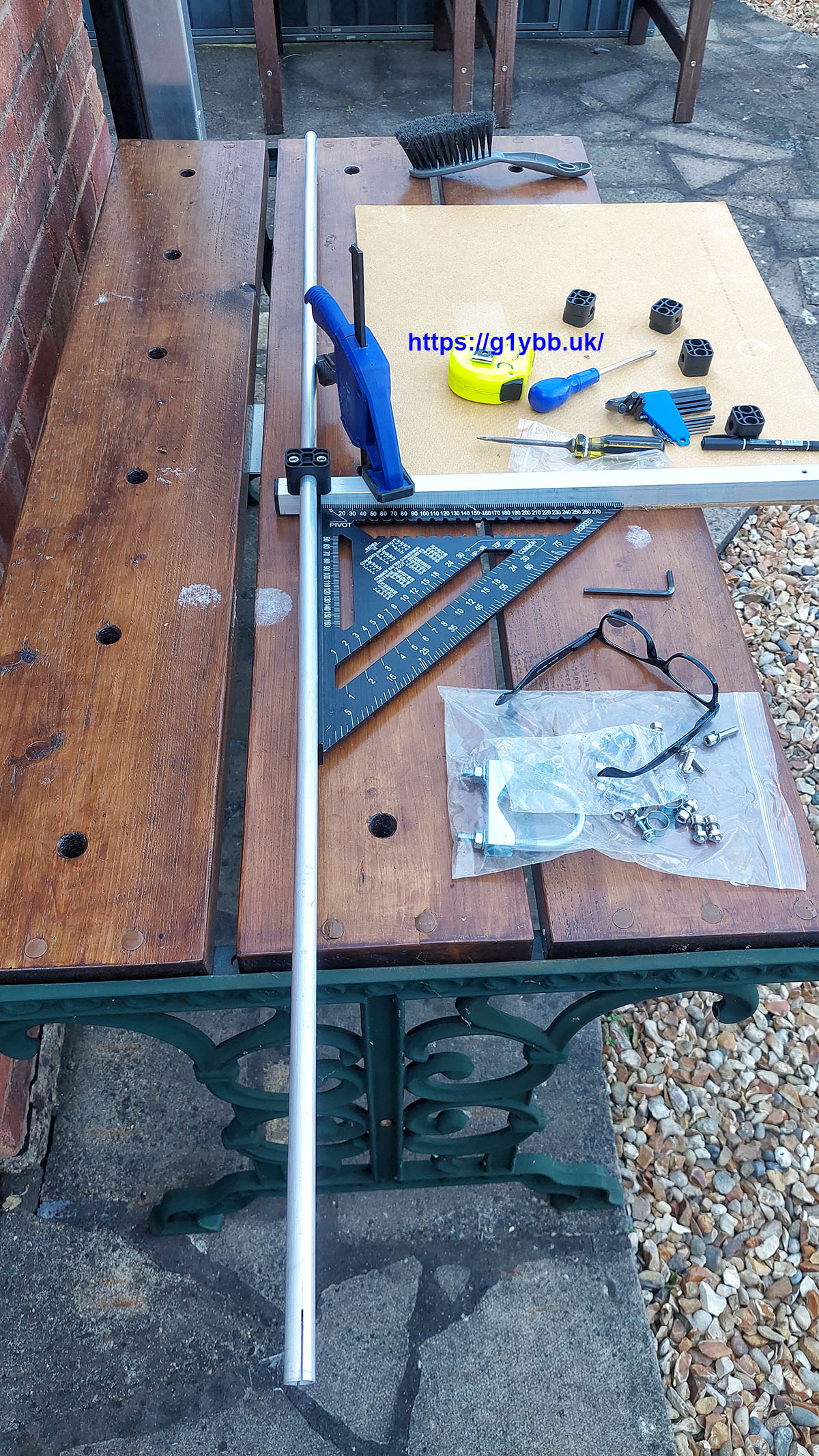
Unravelling the bundle gave me this set of parts:
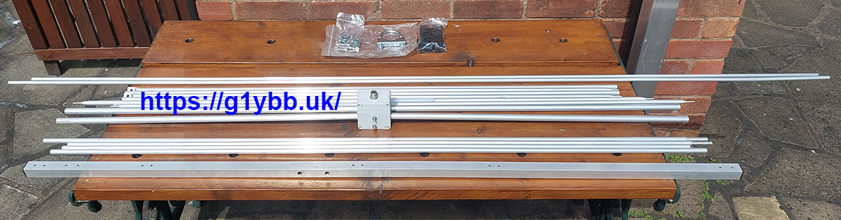 which includes a set of Stauff style element mounts, stainless fittings and a single U bolt for fixing boom to mast.
The first thing of note to me was that all the element mounting holes on the 25mm square boom were tapped holes:
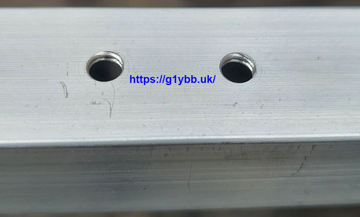 I must admit I wasn’t feeling very confident about that in terms of mechanical strength but they seemed to tighten down securely. Note that I did tighten using the short arm of the Allen key to reduce possible over torquing.
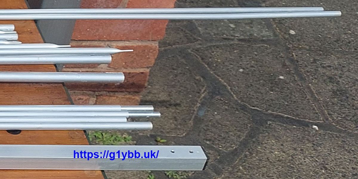
The 6m elements are 12mm diameter rather than the 10mm specified in the DK7ZB design. I assume this was done in order to facilitate the joining ferrules used to shorten the shipping length. The corners of the 10m moxon are formed with flattened and drilled ends. The 4m elements were 10mm single piece elements:
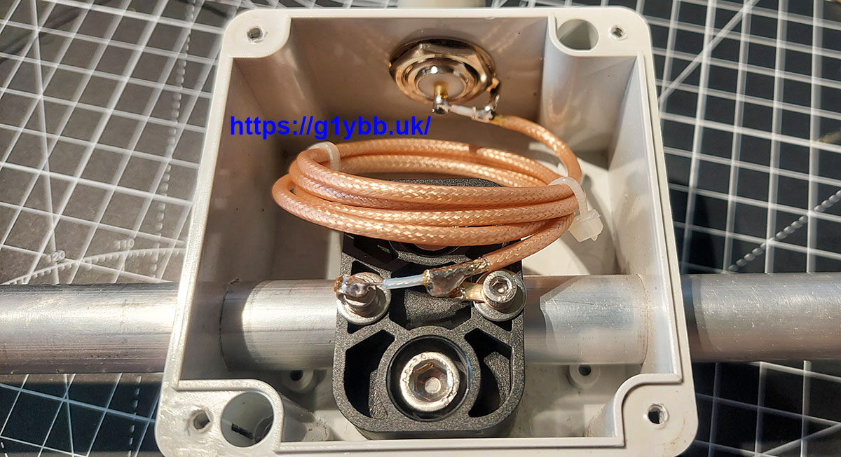
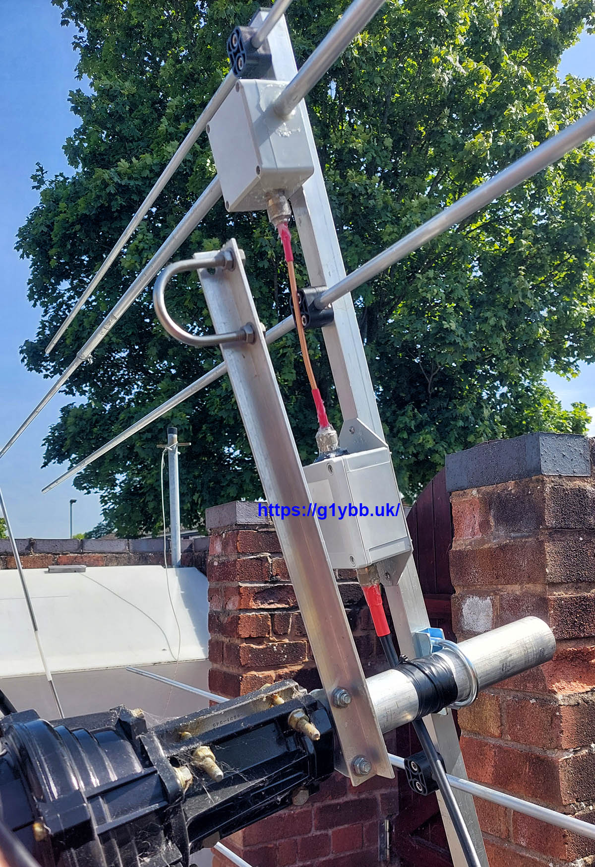
The antenna came with no assembly instructions (from new) and Clive couldn’t remember if it was the lower or higher power version so the first thing to do was examine the choke in the feed box. Here I found the biggest disappointment so far (and worse later on!). The DK7ZB design recommends a 6 turn ferrite common mode choke on 43 core but here I found a simple ugly balun type ‘choke’:
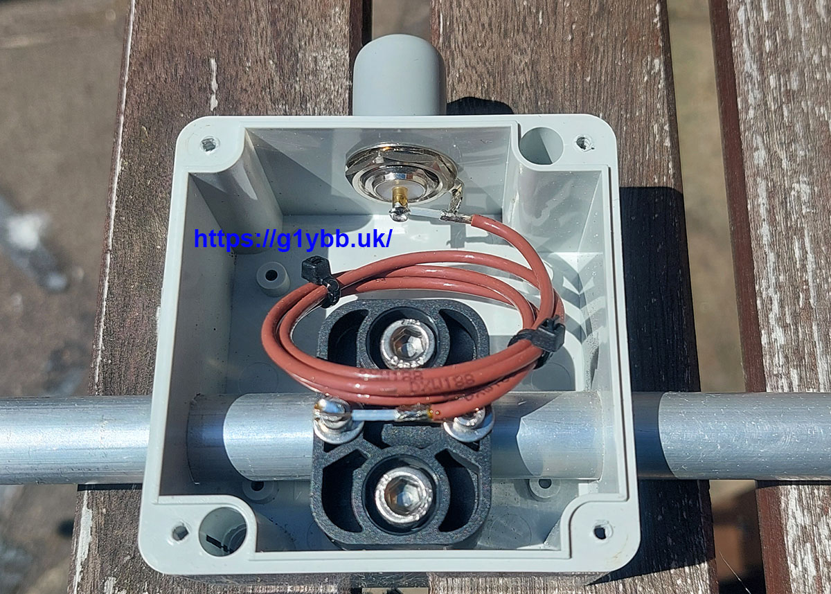 On the up side the dipole box is a good stiff ABS box and though still only 2 fixings to the boom looks like it shouldn’t droop too much like some driven elements. Also an N-type socket used rather than an SO-239 banana plug socket. The ugly ‘choke’ was made from an RG-188 based Teflon coax so this would be the lower power rated version.
A sort through the Stauff copy clamps and fixings soon revealed which clamps and fixings were for each element and the position of them is fairly self evident so assembly was commenced. As is typical with Stauff style element mounts there is loads of play between the mount and the fixings so I found the square was essential to line them up:
10m centre parts and 4m elements fitted:
Next up were the 6m elements. On my initial inspection I assumed the 6m elements were meant to slide together on the ferrules and be retained by a centre punch as I noticed one ferrule was centre popped as supplied. But a closer rummage through the fixings bag revealed 4 short self tapping screws. There seemed no other sensible place to use these so I figured they must be to secure the element halves together. In this picture the centre pop by the pink pen was as supplied, the pop on the right is mine:
I then set about drilling pilot holes and screwing the tappers in securely:
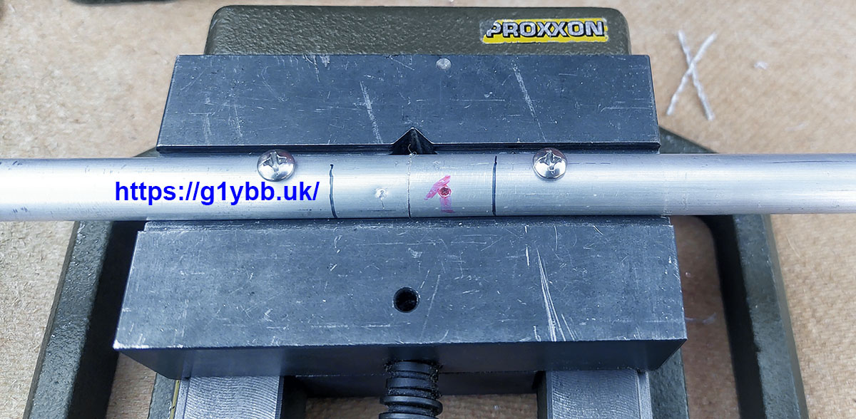 The thin marker pen lines are the edges of the Stauff mount so I didn’t drill in a stupid place!
After fitting the 6m elements it looked to me like there was a design flaw about to hit me. When designing my dipole boxes for my elements in 3D CAD I always fit a model of the feeder into the assembly to ensure the coax will pass any nearby elements. I fetched an LMR400 patch lead and proved myself correct. No way at all was my feeder screwing onto the dipole box!
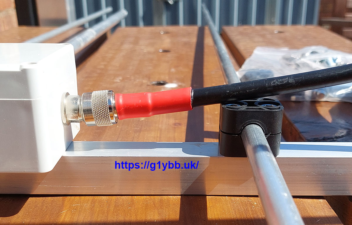
Hmmm. Not great. There is room in the dipole box to mount the N-type higher to avoid this issue without any effect of performance. LMR400 is same size as common RG213, surprised this issue exists. It would be possible to reverse the dipole box but the 4m Stauff holders are the same size and even closer. Poor show.
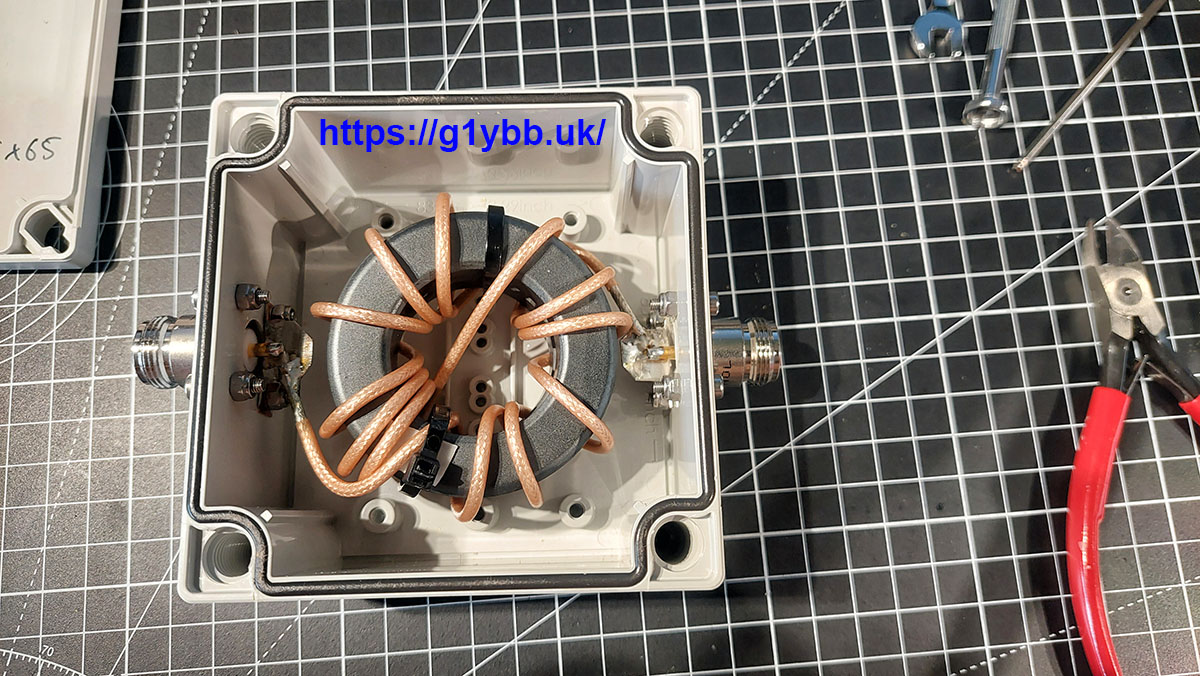
So what to do. I’d already toyed with the idea of making a separate G3TXQ choke balun box for this as there is not enough room in the dipole box to fit an FT240 toroid but I was keen to press on so thought I wouldn’t bother. But now it would give me the opportunity to utilise a short connecting cable between them to overcome this issue. So I decided that would have to be the way to go. For that I would use RG316 as it is higher rated than RG188 and also because I couldn’t fit my RG142 one into the box I had as RG142 is too stiff! This is my G3TXQ choke on 2x FT240-52 cores:
So I then also decided I may as well give Clive a free upgrade and swap out the RG188 for RG316. Bloody good job too! On opening the box again on the bench with my glasses on I spotted this!!
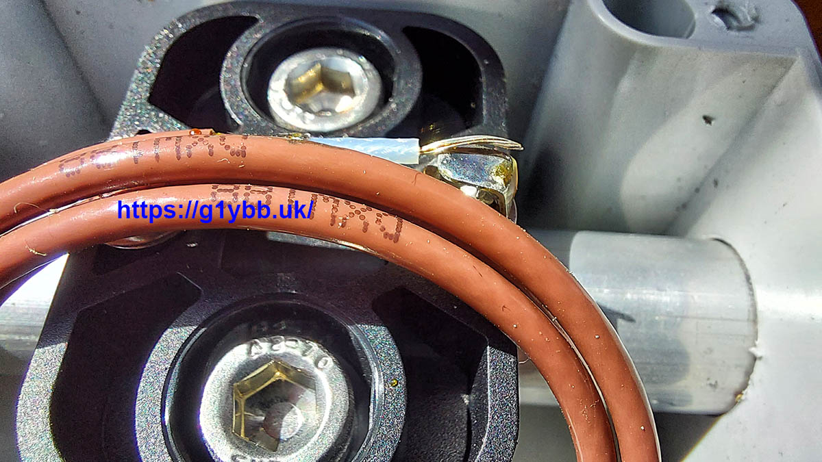 Centre of coax NOT soldered to the dipole half!! Very poor I am sorry to say.
RG188 ugly choke replaced with RG316 version for when I return the loaned antenna to Clive G8LNR:
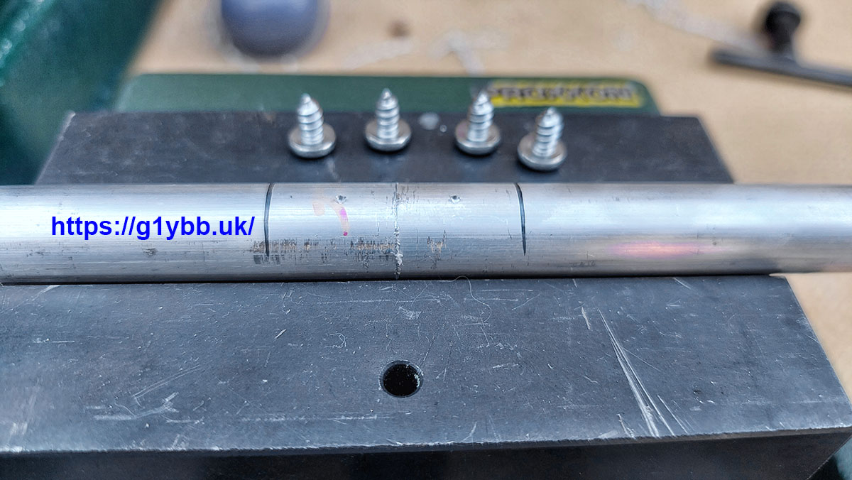
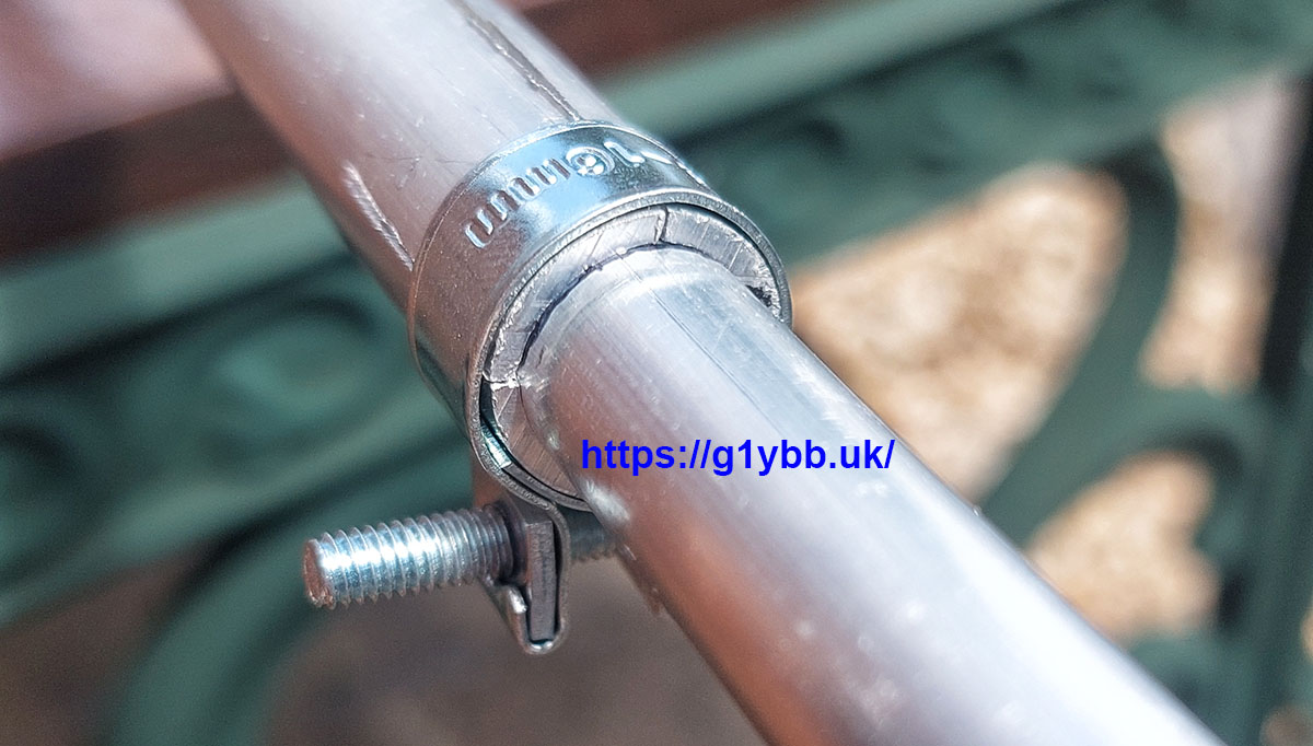
With the dipole centre re-fitted I now started to fit the rest of the 10m elements and immediately found another issue not covered by the VPA Systems implementation mechanically. Even fully tightened up, the nut and bolt style jubilee clip (much better than worm drive IMO) could not compress the outer tube enough to grip the inner tube. I could still move it quite easily by hand. The DK7ZB designs do use all metric tube and some of the telescopic joints do have a lot of ‘slop’ to take up. My 6 element 50MHz DK7ZB driven is exactly the same. The dipole ends came with just 2 hacksawed slits (non deburred by the way) which isn’t enough to take up all the slop. You can just see air space above my thin blacker marker pen line and the slit fully compressed together:

My only recourse was to dig out the junior hacksaw and add some slits at 90° to those supplied. That was just enough to get a secure grip onto the smaller section though you can see the edges of the now 4 slits are still almost touching:
Another point of interest now. In the previous pictures you could see my marker pen lines for the position of the smaller 10m section. That was marked at my simulated position to slighter lower the resonance point of 10m from the DK7ZB design so I could use it with a better SWR at the digital end but still OK in SSB. The DK7ZB design page recommends adding 150mm to the extended elements. VPA systems have taken another needless shortcut here.
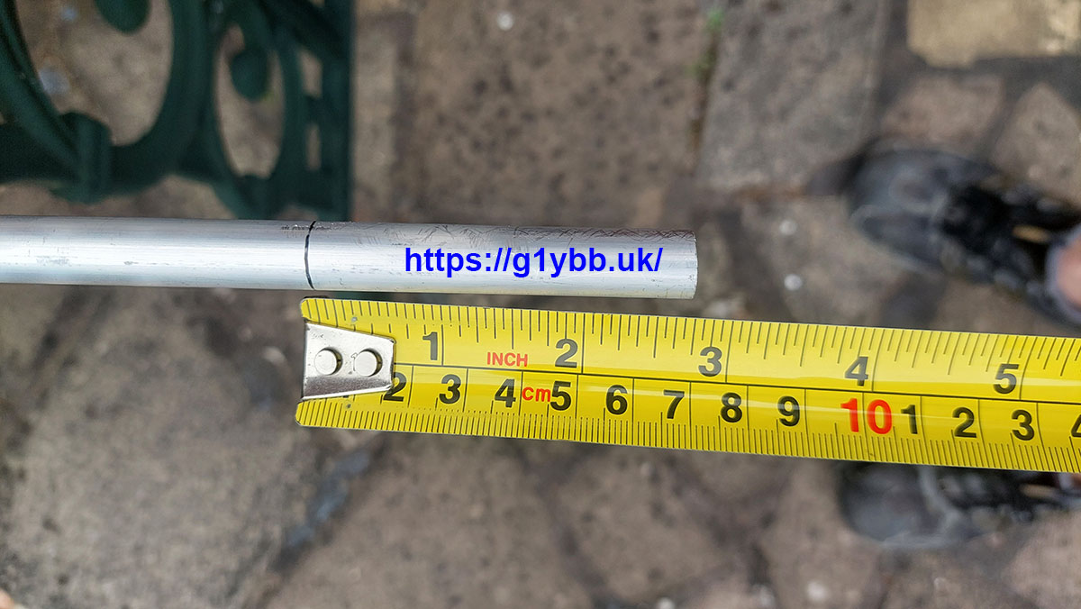
Bearing in mind the ‘slop’ mentioned above a very short insertion means the smaller sections will hang down needlessly due to the internal play rather than gravity induced flex.
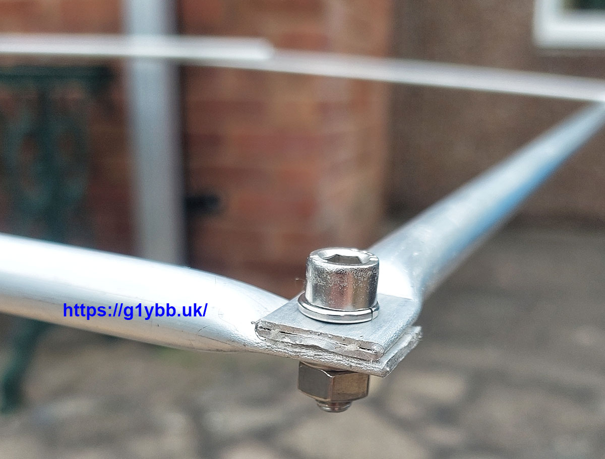
Anyway, moving on, the ends of the 10m moxon are fitted with the supplied bolts. As an aside, during a small brain fart induced by the way I had the two 10m end assemblies laid out together I thought someone had assembled the two reflector ends together and the two driven ends together. So I tried to separate them to correct that. It was NOT happening. The insulator is really firmly fixed into the the ends of the elements. Once I realised I was being stupid we were all good but with the knowledge those ends are NOT coming apart in the wind.
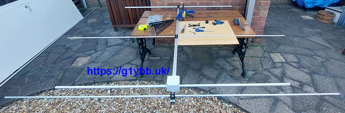
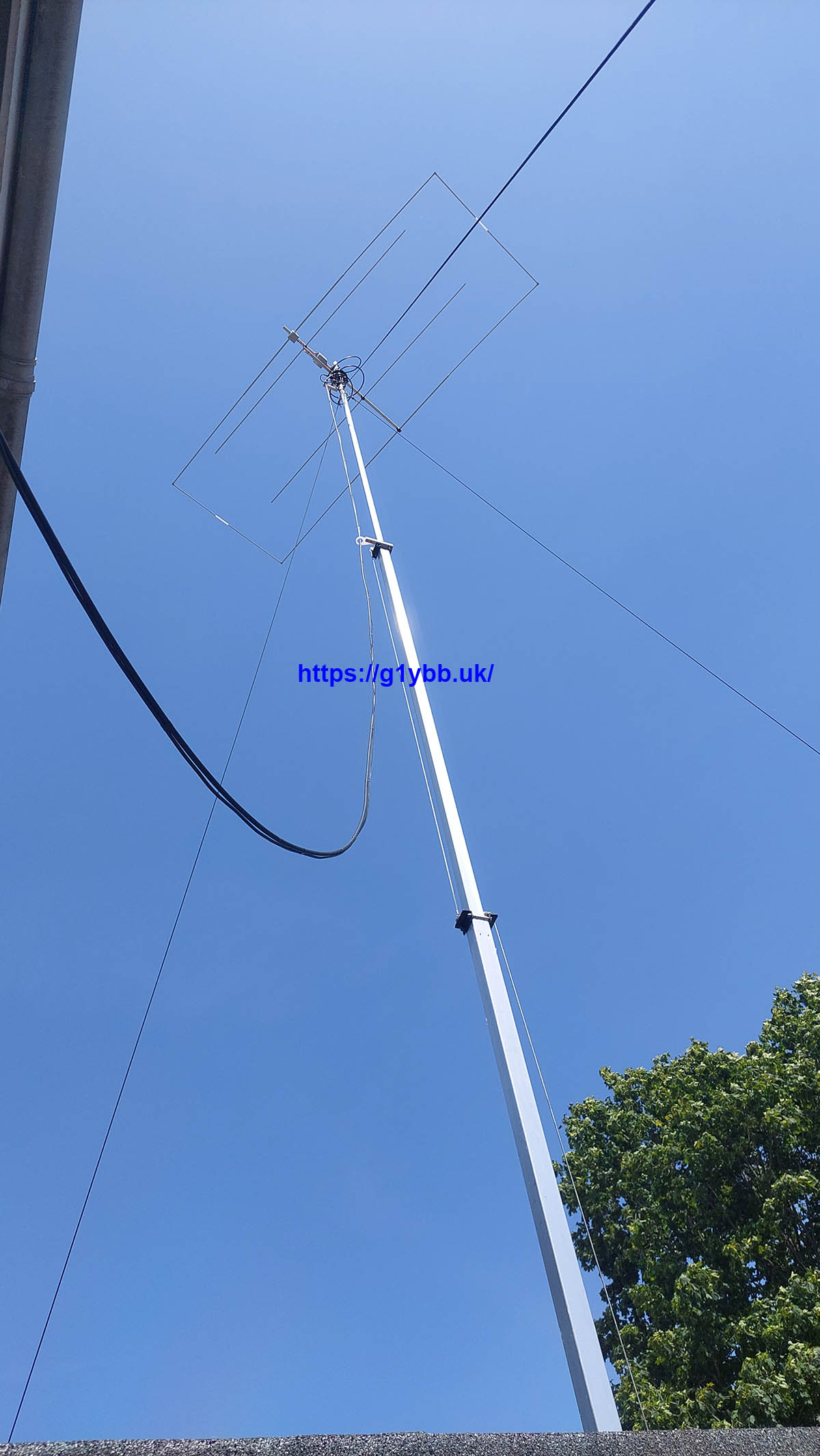
With all the elements now fitted the G3TXQ common mode choke and linked it to the dipole with an RG142 cable and fitted it to my home brew mast. (Ignore the aluminium angle arm-I moved that to the same side as the boom after the picture was taken):
Time to wind it up and test it.
I forgot to save any analyser plots of the initial measurements as we were keen to get it working more than anything.
First tested was 10m. I had already simulated the DK7ZB design as mentioned earlier so I had set the 10m section to my calculated width intended to slighter move the SWR dip lower in the band. As it turned out the dip was about 28.4MHz and the antenna was perfectly usable between 28.0 to 29.0 with the worst SWR about 1:1.4.
Next I looked at 6m. It was miles out. I expanded the sweep range and found the best SWR dip at 49.83MHz. I then put the sizes of the 6m elements as supplied into my 4NEC2 model and found the exact same results:
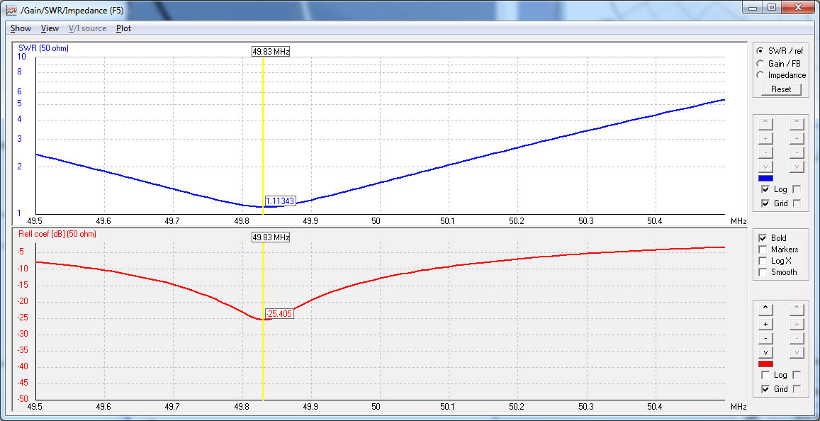 Now at least I knew I had a known reference point to fix this.
4m was even worse. This was even further out but too high in frequency meaning there was no cutting to be done. I decided that although tri band would be nice my 7610 doesn’t have 4m so I would need to set up the 7300 so for now I would just ditch 4m. We removed the 4m elements and wound the antenna back up to check things hadn’t changed much. 10m resonance changed very slightly, no noticeable effect on 6m, which is encouraging for adding 4m back on at a later date.
I used the simulation to find out how much to shorten the 6m elements by then dug out the hacksaw and cut off exactly 12mm from each end.
On 10m I looked to see how much I needed to move the ends out to get closer to my preferred lower resonance point. Really it was more than 20mm, but as there is so little tube in the joints I figured 20mm would have to do.
We wound the mast back up and the SWR curves we really good, just where I wanted them.
The proof of the pudding is of course, does it work? I had a couple of hours operating on FT8. 6m wasn’t that great though I did get a couple across the pond, my first ever on 6m. I spent more time on 10m and got some decent DX. I have only ever made about 5 QSOs before on 10m with my cobweb so it was good fun. 6m QSOs are orange.
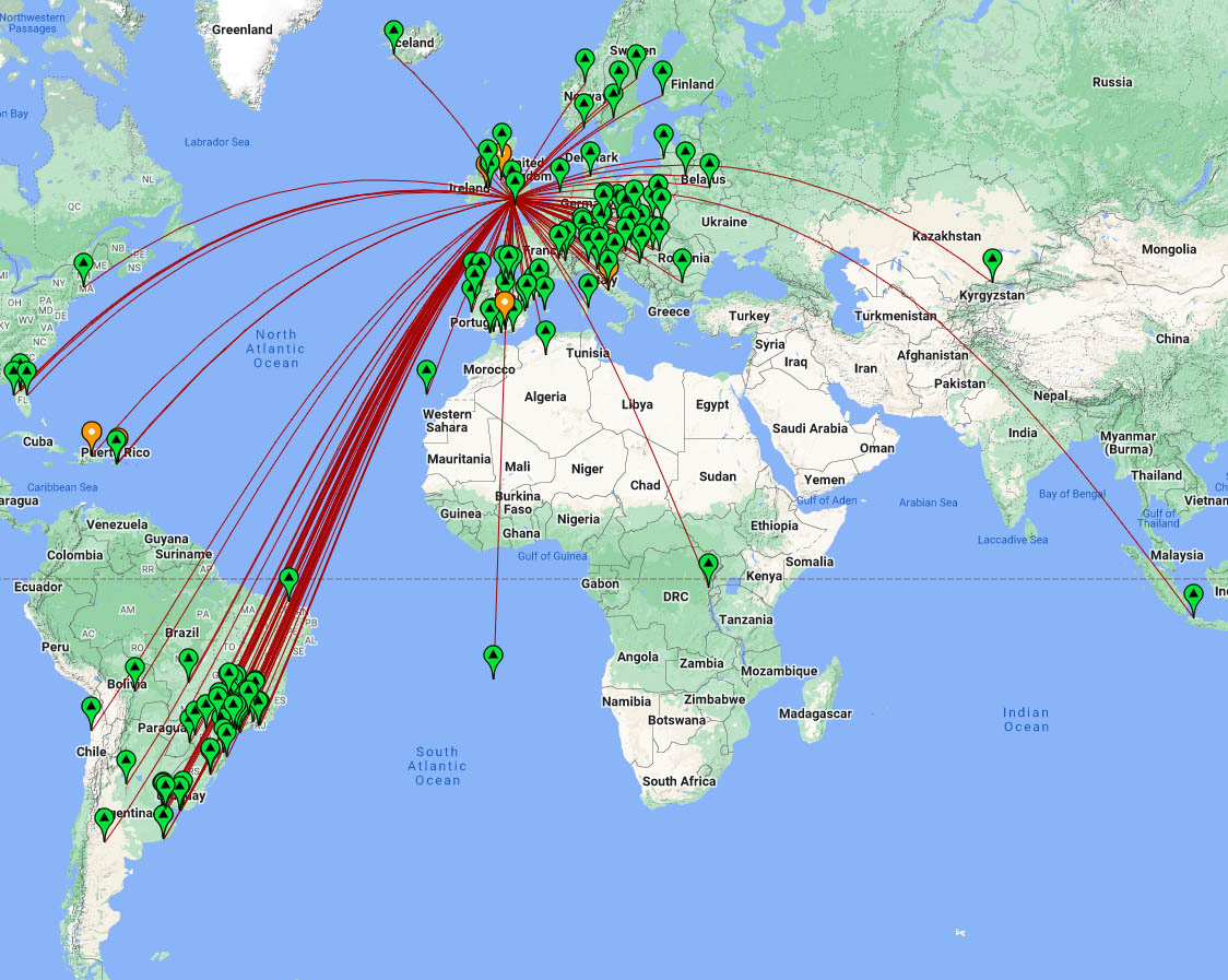
The same weekend was the 50MHz R1 contest where I had a few hours operating. I missed the best Es but got a few, and around the UK in very poor conditions locally:
Conclusion.
Whilst I appreciate this antenna is more at the budget end of the market and is nicely lightweight which I favour personally, I must say I am glad I didn’t pay for it myself. The ‘ugly’ balun is a shortcut that might very well be adequate (IF it was actually soldered !!) and work but the miles off tune 6m and 4m elements cannot be forgiven. It took me minutes in the free 4NEC2 program to prove that the 6m would never work in band. For someone who is less ‘handy’ with making antennas (eg someone likely to buy a ready made antenna…) as it was supplied only 10m was usable and that only if spring tension in the RG188 happened to make contact with the driven element.
It’s a great shame as it’s so nearly there. More attention to detail (at no real extra cost – better slits in the 10m centre parts, move N type up so you can use decent feeder, few more inches insertion on the 10m outer elements, check soldering is soldered etc) and this would be a viable alternative to making your own. For me it was a simple task to adapt what I had to work and saved me some many hours of ordering and making but I do know for less cost I would have an almost equally lightweight version but one where it could take a pigeon sitting on the ends of the 10m moxon.